
PRACTICAL DESIGN AND IMPLEMENTATION OF A CAVE
SYSTEM
High Quality Four Walls CAVE Howto
Achille Peternier, Sylvain Cardin
Virtual Reality Laboratory (VRLab), Ecole Polytechnique Fédérale de Lausanne (EPFL), Lausanne, Switzerland
Frédéric Vexo, Daniel Thalmann
Virtual Reality Laboratory (VRLab), Ecole Polytechnique Fédérale de Lausanne (EPFL), Lausanne, Switzerland
Keywords: CAVE, low cost, immersive Virtual Reality, calibration, tracking, stereographic rendering.
Abstract: CAVE systems are nowadays one of the best Virtual Reality (VR) immersive devices available for render-
ing virtual environments. Unfortunately, such kind of hardware is extremely expensive, complex and cum-
bersome, thus limited in its spread. Several cheaper solutions already exist, but they implement usually only
a subset of features of a professional CAVE. In this paper we describe how we have built a low cost CAVE
with four screens (three walls and a floor), stereographic rendering and user tracking by only using hard-
ware commonly available on the market and free software, we show the different solutions and work-around
we implemented to solve the problems we encountered and we conclude with an evaluation of our system
by using two applications we developed with it.
1 INTRODUCTION
Immersive environments giving the illusion of being
surrounded by a fictive world are a key feature re-
quired by many Virtual Reality applications and are
extremely difficult to simulate. Visual immersion
needs specific, expensive and cumbersome hard-
ware, such as head-worn displays (HMDs), large
displays or CAVE systems (Sutcliffe et al., 2006).
HMDs offer a good level of immersion, but often
suffer of a small field of view and isolate the user
and his/her body both from the real and the virtual
world (Czernuszenko et al., 1997). Spatially Immer-
sive Displays (SIDs), like wall-displays and CAVEs,
have the advantage of being multi-user, to allow
persons to be physically within the virtual environ-
ment and feature a wide field of view. Many studies
(Tyndiuk et al., 2005) (Buxton et Fitzmaurice, 1998)
showed that devices based on large displays offer a
better immersion and cognitive interaction with a
virtual 3D environment. Due to the high cost of pro-
fessional solutions and their complexity, the prolif-
eration of such kind of environments is limited to
institutes or organizations able to pay and manage
such structures.
In this paper we describe how we have built a
four sides CAVE (three walls, one floor) by using
standard market products and internally developed
software, without requiring any third part or high-
end professional product. Despite of this, we
achieved to manage a very flexible, robust, high
quality and fast CAVE environment, featuring
stereographic rendering, a good calibration system
for walls and sensors, head-tracking and last genera-
tion graphics comparable to most recent video
games. We expose how we managed every aspect
and solved all the accuracy and practical problems
of this project in order to show how home-made
SIDs can be created with a minimal effort and in a
relatively cheap way, without sacrificing the quality.
We compare our results with other similar frame-
work and establish a fair evaluation. Finally, we
illustrate some applications we developed with our
system to show what it is possible to handle with our
environment.
2 RELATED WORK
The CAVE Automatic Virtual Environment (or sim-
ply CAVE) has been originally conceived in 1992
129
Peternier A., Cardin S., Vexo F. and Thalmann D. (2007).
PRACTICAL DESIGN AND IMPLEMENTATION OF A CAVE SYSTEM - High Quality Four Walls CAVE Howto.
In Proceedings of the Second International Conference on Computer Graphics Theory and Applications - AS/IE, pages 129-136
DOI: 10.5220/0002080701290136
Copyright
c
SciTePress

by Thomas Defanti and Dan Sandin and imple-
mented by Carolina Cruz-Neira at the University of
Illinois at Chicago (Cruz-Neira et al., 1992). The
idea behind this project was to create a VR system
without the common limitations of previous VR so-
lutions, like poor image resolution, inability to share
the experience directly with other users and the iso-
lation from the real world. A head tracking system is
used to produce the correct stereo perspective: this
allows the user to see his/her entire environment
from the correct viewpoint, thus creating a compel-
ling illusion of reality. Real and virtual objects are
blended in the same space and the user can see
his/her body interacting with the environment.
Over the past decade, interest and development
of CAVEs and SIDs have become increasingly sig-
nificant, some of them becoming also commercial
products like Barco (www.barco.com) and VRCO
(www.vrco.com). Despite of the amount of devel-
opment in this direction, both professional and cus-
tomized solutions are still extremely expensive, be-
cause they are often close to prototypes requiring
specific cares, like the CAVE-like display developed
by Gross et al. (Gross et al., 2003) to project and
acquire 3D video content.
There also exist reduced versions of CAVE sys-
tems, with fewer walls or even transportable. One of
them is the V-CAVE (made with only two walls,
hence the name V-CAVE, because the two screens
form a letter “vee”). Two digital projectors point
into the corner of a room, avoiding the requirement
of dedicated screens (Jacobson, 2003). This system
(Jacobson et Hwang, 2002) is also based on the top
of a game engine which offers good quality graphics
on personal computers but sacrifices the versatility
of their approach for context other than a walk-
through of static pre-processed models, thus reduc-
ing the use of their software in contexts with ex-
tremely dynamic graphics. We aimed at a more
complex system with four walls and a more generic
engine in order to be used in contexts also requiring
extremely dynamic geometries or modifications to
the scene graph.
Different approaches have been studied for track-
ing the user position inside the CAVE. The recurrent
problematic depends on the physical characteristics
of the system. The most used indoor tracking sys-
tems are based on active vision algorithms or on
magnetic tracking. Both of these solutions are costly
and have specific drawbacks. The vision based ap-
proach with markers, like the Vicon system, uses
video acquisition from cameras and is sensible to
obstructions. In a CAVE framework, the field of
view of the cameras has to be wide enough to cover
a large area of interaction, thus multiple cameras are
necessary to improve tracking accuracy and in order
to cover a larger area. There also exist cheaper im-
plementations using passive vision based systems
with passive markers and standard cameras, running
on free library such as ARtoolkit and good enough
to produce accurate results in stereo acquisition
(Koo et al, 2004).
Magnetic tracking, using systems such as the
MotionStar
tm
one (www.ascensiontech.com), is
widely used for full body motion tracking. The main
disadvantage in using this technology is that most of
the CAVEs are built on iron frames and metallic
masses may alter the magnetic field measured by the
sensors. Research at the Illinois University (M.
Ghazisaedy et al., 1995) offers a good illustration of
the magnetic field distortions. They also present a
method to calibrate the system to improve the accu-
racy, by correlating the measurements with ultra-
sonic sensors.
Sauter described a low-cost CAVE solution
based on generic Windows and Macintosh com-
puters to make this technology more accessible
(Sauter P. M., 2003). We adopted a similar but up-
dated architecture for our framework. We also ex-
tended the low-cost idea to the tracking system and
by improving calibration tools to solve common
problems of home-made virtual devices. Based on
these experiences, the next part will describe our
system and its different implementations.
3 SYSTEM
In this section we describe our solution, first with a
brief overview of the whole thing then by explaining
every aspect in detail.
3.1 System Overview
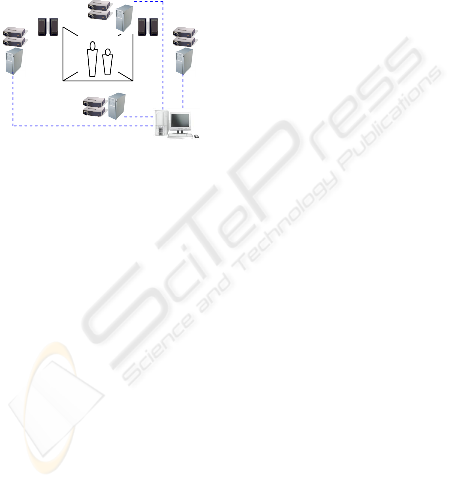
Our CAVE features three walls and a floor. We used
eight off the shelf LCD beamers (Canon LV-7210)
connected to four personal computers (Intel Dual
Xeon 3 GHz, with dual DVI output NVidia Geforce
7800), generating and projecting images on a cinema
screen folded in the form of a box (for the walls) and
on a white wooden panel (on the ground).
Back-projection has been used for the walls, di-
rect one for the floor. A fifth master PC leads the
four clients, through a server-client architecture con-
nected via a private 1 Gigabit LAN. The server PC
also manages a 5.1 audio system to bring spatial
sounds in the environment.
The system works both in mono and stereo-
graphic rendering, either active (shutter glasses) or
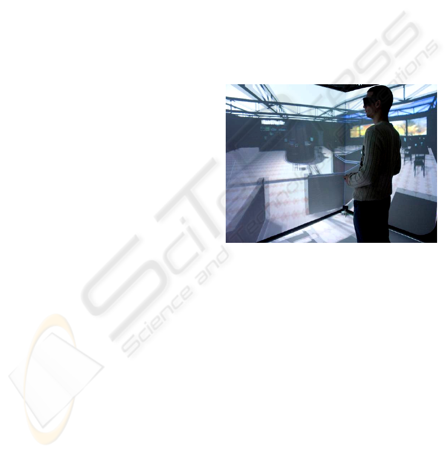
passive (red and blue glasses). The CAVE is 2.20
meters high, 2.50 meters large and 1.80 meters
GRAPP 2007 - International Conference on Computer Graphics Theory and Applications
130
depth. Up to three users can comfortably stay within
the framework.
Software side, our environment uses a graphic
engine specifically developed in our lab: server and
clients run local instances of the same engine syn-
chronized through the server. Synchronization in-
cludes models, scene graph, textures, shaders, etc.
thus obtaining a full dynamic environment.
Figure 1: Hardware setup overview.
3.2 Graphic and Audio System
Our CAVE is running a modified version of an in-
ternally developed graphic engine first created for
pedagogical purposes and called MVisio (Peternier,
2006).
MVisio (Mental Vision) is a lightweight, robust
and user-friendly 2D/3D graphic engine. The goals
of MVisio are several: offering an extremely easy to
use and intuitive interface to 2D/3D graphics, being
able to run on almost every available desktop PC or
laptop by automatically adapting the rendering qual-
ity and settings, being also able to work on hetero-
geneous devices (PC, PocketPC) or operative sys-
tems (Windows and Linux), being compact in sizes
and system requirements and finally being fast and
modern (featuring advanced rendering techniques
such as soft shadows and post-processing effects like
bloom lighting through OpenGL and OpenGL|ES).
Because of the flexibility and already tested robust-
ness of this software, we decided to add CAVE ren-
dering to its features.
MVisio for CAVE uses a server-client architec-
ture based on low-level TCP/IP communication be-
tween wall and floor client PCs and the main server
computer. Thanks to the speed of the local Gigabit
LAN the latency generated by the network is ex-
tremely low. Client machines run on a minimal in-
stallation of Windows XP. A service runs perpetu-
ally waiting for connections from an MVisio for
CAVE server. MVisio server sends a wake-up re-
quest to all the services running on the different cli-
ent machines, the service starts an MVisio local cli-
ent which is an interpreter of high-level commands
(move, rotate, display, etc.) sent from the server.
Every operation effectuated on the server PC is for-
warded to the clients. This include data loading (tex-
tures and geometries are synchronized at startup),
shaders, modifications to the scene-graph, etc. Run-
ning MVisio on a local PC or in the CAVE just re-
quires for the end-user to modify a couple of lines of
code during initialization of the graphic engine: eve-
rything else is automatically handled by our soft-
ware. This task can also be skipped by using con-
figuration files, in order to allow to exactly the same
source code to switch from the single PC version to
the CAVE version of MVisio in a completely trans-
parent way, by just passing a different configuration
file as argument. MVisio CAVE clients can be con-
sidered as copies of the MVisio engine running re-
motely and directly manipulated by the user: infor-
mation is synchronized through the network connec-
tivity between the machines. The different frusta are
computed server side and independently forwarded
to the specific clients. The architecture is completely
versatile and can handle from one remote client up
to any arbitrary number of displays. It is interesting
to mention that our architecture can also be used as
remote rendering system to display real-time images
on a remote PC somewhere in the world and not
being a part of the CAVE private network. This fea-
ture also theoretically allows data synchronization
between two or more remote CAVEs.
The audio engine has also been developed in our
laboratory. It features spatial audio positioning
through the OpenAL API (www.openal.org), audio
streaming (from .WAV and .OGG files) as well as
DSP effects through Creative EAX 2.0 (devel-
oper.creative.com). The main advantage of using our
own audio engine is that it perfectly fits with MVi-
sio, so adding audio sources to a scene graph is
straightforward and robust. Contrarily to the graphic
subsystem, the audio engine doesn’t require to be
instanced on each CAVE client and runs only on the
server PC that is connected to the five Dolby 5.1
loudspeakers (see figure 1). Audio and images are
synchronized by using the server timer.
3.3 CAVE Display Calibration
We used a market level flat home-cinema screen as
display for the three walls and a white painted
wooden panel as floor. To fold the home-cinema
screen in order to create a box surrounding the user
we used a transparent nylon wire stretched along the
corners of an iron frame. This solution caused a ma-
jor drawback: the screen folded with a curve around
the corners, assuming the shape of a parenthesis.
PRACTICAL DESIGN AND IMPLEMENTATION OF A CAVE SYSTEM - High Quality Four Walls CAVE Howto
131
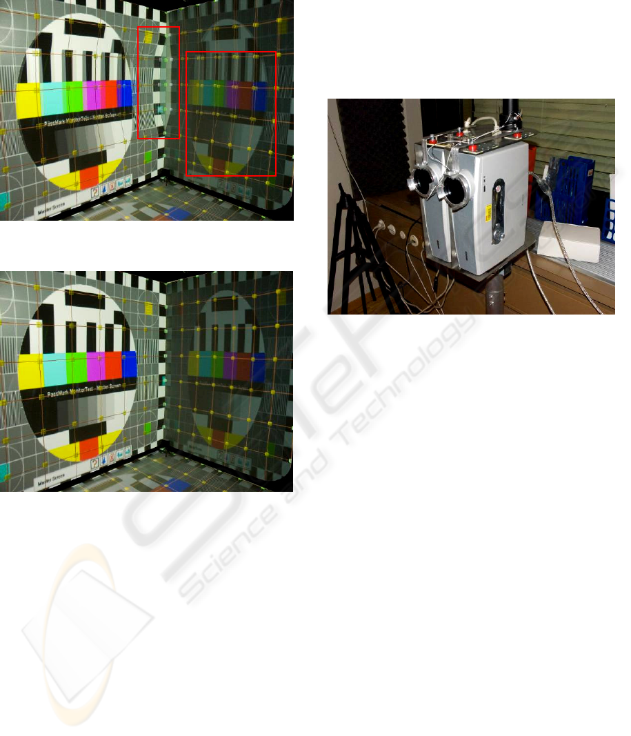
Also projecting images from two separate projectors
generates an unavoidable misalignment, despite an
accurate calibration of their convergence.
Figure 2: Non calibrated walls, notice the glitch between
the two displays (left red box) and the grid not aligned for
stereographic rendering (right red box).
Figure 3: Walls after calibration.
We managed to solve these problems by mean-
ings of calibration software, allowing the user to
manually draw a shape accurately following the
screen borders and by using this shape as a polygon
to render the images into. Basically, the CAVE per-
forms a high resolution (1024x1024 pixels) render-
to-texture using the OpenGL frame-buffer object
extension. This texture is then mapped onto the
polygon previously adapted to fit the display shape.
To improve image superposition for stereo render-
ing, we also used a grid with moveable control
points. By matching the control points of the grids
projected from the two projectors, we avoided de-
formations caused by beamers being physically pro-
jecting from two points slightly different in the
space. An accurate calibration showed per-pixel ac-
curacy and almost entirely removed the corner ef-
fect.
We developed the calibration software by reus-
ing parts of the MVisio for CAVE engine, thus cre-
ating again a server-client architecture. To simplify
and accelerate the calibration procedure, a user just
has to run this software and access the different grids
and control points by using a wireless joystick. This
way, the four walls can be calibrated at the same
time by one user from within the CAVE, instead of
having to login on every CAVE computer separately
and adjust the grids with a mouse, one by one.
Figure 4: Dual-projector assembly with shutters.
This calibration solution also solved another
problem. Our projectors have a maximal resolution
of 1024x768 pixels. In order to cover the side wall
according to the space available, we had to place
them vertically, thus having different pixel resolu-
tions between the main and floor screens (768 pixels
vertically) and the right and left ones (1024 pixels).
Moreover, pixel sizes on the CAVE walls are not the
same on each wall, because of the different distances
between the projectors and the displays. Anti-
aliasing combined with an accurate match of the
render-to shapes made this problem almost not no-
ticeable. By using these techniques, we managed to
achieve a continuous image on the different walls
which creates a great immersion. To improve it a
step further, in the next part we describe how we
added depth information to the virtual scene through
stereoscopic rendering.
3.4 Stereographic Rendering
Stereographic rendering requires two images to be
generated and displayed at the same time, one com-
puted for the right and one for the left eye. Top-level
solutions use a high refresh rate CRT projector fea-
turing up to 120 Hz as refresh frequency. Through
the use of shutter glasses, such systems can display a
maximum of 60 images per second per eye. The
video projector has to be driven by a professional
graphic card which includes a synchronization out-
GRAPP 2007 - International Conference on Computer Graphics Theory and Applications
132
put for the shutter glasses. This output changes the
polarity of the shutter glasses according to the verti-
cal synchronization of the display. Professional
graphic cards and high quality CRT projectors are
very expensive and require specific periodical cares
to correct convergence.
We used a different approach in our system by
adopting two standard LCD projectors (one per eye)
with a built-in refresh rate of about 60 Hz (through a
DVI cable). To achieve proper superposition of the
two rendered images we built home made supports
for the projectors. These supports allow fine adjust-
ment of the position and orientation of the beamers.
Figure 5: Blue & red stereo in the CAVE.
The idea is to let the two LCD beamers continu-
ously showing the images and synchronizing left and
right eyes by putting ferroelectric shutters in front of
the LCD lenses. This way, user shutter glasses syn-
chronized with the ferroelectric shutters in front of
the projectors allow a fixed number of images per
second per eye, independently from the refresh rate
of the display devices. In our configuration we used
a switching between left and right eyes at 70 Hz
which is the limit of the shutter glasses we adopted.
We also implemented an old-style blue & red
glasses stereographic system to be used during pub-
lic demonstrations when a large number of visitors
access the CAVE at the same time, because of the
low amount and fragility of the shutter glasses. Fi-
nally, blue & red glasses can also be used for stereo-
graphic testing on the virtual CAVE (see 3.6) on a
single computer.
Stereographic rendering is improving immersion
by adding depth information to the surrounding im-
age. But while the user is moving, the perspective
referential should be accordingly displaced to avoid
break in presence. The next part will present our
solutions to correct this effect by tracking the user
head.
3.5 Head Tracking, Environment
Walkthrough
Head tracking is a key feature in a CAVE system
required to correctly generate the illusion of a sur-
rounding space around a specific user. Head-
tracking is used to determine the position of the user
within the CAVE physical space, in order to know
his/her distance from the walls and compute a cor-
rect projection.
Figure 6: The cheapest solution: blue & red glasses with a
head-wearable lantern. Detail picture on the left shows the
lantern in the darkness.
For testing purposes we implemented three dif-
ferent methods to track the user’s head position. The
first method we studied was to use a camera and a
vision based algorithm to track markers located on
the user’s head. The open source library ARtoolkit
provided all the necessary functions to treat the
video information in real time and extract 3D posi-
tion and orientation of the predefined markers. We
used a standard Panasonic video camera for the ac-
quisition. The main issue in the setup is the weak-
ness of the vision based algorithms to luminosity
changes. At first we had very poor results due to the
main source of illumination on the markers coming
from the image displayed on the CAVE itself. This
illumination of the markers was changing frequently
and degrades the tracking accuracy. To solve this
problem, a light bulb has been placed inside a small
cube covered with markers fixed on the user head,
creating some kind of head-worn lantern with semi-
transparent markers on the sides, to keep their lumi-
nosity constant and independent from the brightness
of the images rendered on the CAVE walls. This
system provided low tracking resolution at low re-
fresh rate. With proper calibration and filtering it
provides nice results to adjust to small user move-
ments.
PRACTICAL DESIGN AND IMPLEMENTATION OF A CAVE SYSTEM - High Quality Four Walls CAVE Howto
133
As second tracking method we used magnetic
trackers. These sensors are composed by three in-
ductances which measure the magnetic field induced
by a referential field generator. The whole system is
built by Ascension technologies under the name Mo-
tion Star system. This system provides 6 degree of
freedom tracking with a really high resolution for
the orientation and around 1 cm of accuracy for the
positioning. The main advantage of this system is
the high refresh rate with a correct accuracy.
We recently acquired an optical tracking system
with active markers using multiple viewpoints. This
system is composed by a set of linear video cameras
which keep track of different LEDs which blinks
according to their identifier. A complete dedicated
hardware is in charge of the acquisition from multi-
ple view points and computing of the positions of
the markers. This system provides great accuracy
around a few millimetres in positioning, which gives
perfect results for our kind of applications.
To simplify calibration of sensors within the
CAVE space and generalize the conversion between
the values returned and the CAVE coordinates, we
developed a simply and fast method using reference
images projected on the CAVE walls and three laser
pointers. We built a three orthogonal axis rigid sup-
port to put three laser pointers onto with a place
where to lock the sensors on its origin. By aligning
the three laser dots on a reference grid displayed on
the walls and the floor, it is possible to easily match
the reference points for converting sensor spatial
coordinates to CAVE coordinates.
3.6 Virtual CAVE
Developing for a CAVE environment often requires
the programmers to be near the hardware and to test
directly on the device. This solution isn’t always
practical, mainly when different concurrent projects
share the same CAVE at the same time.
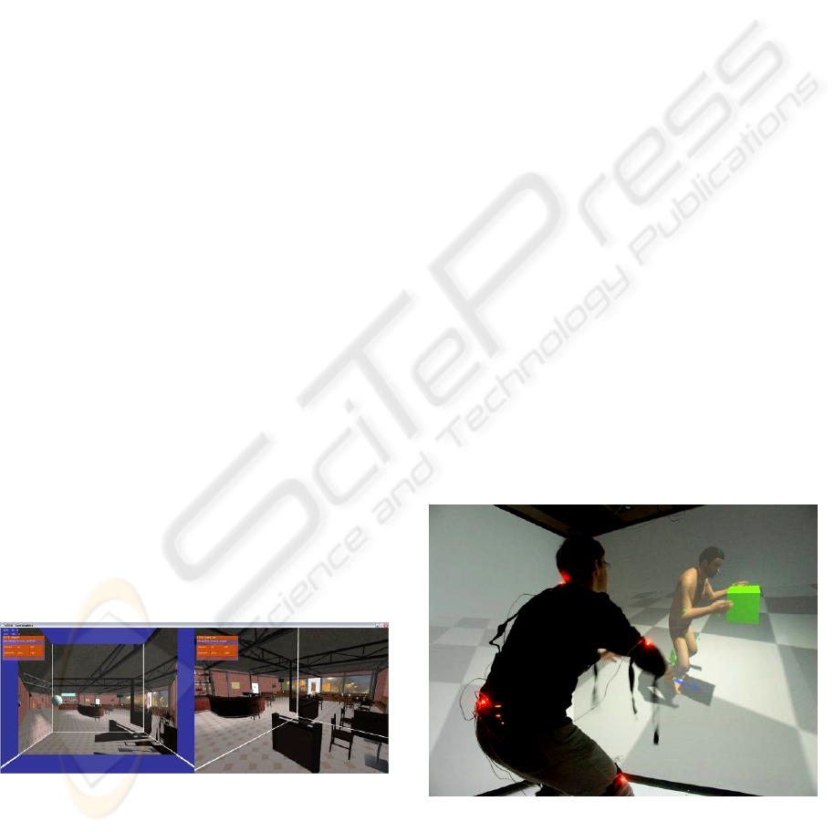
Figure 7: Bar scene displayed in the CAVE simulator. On
the left, the white sphere represents the user’s head, on the
right images as viewed from the user’s position.
To make development of CAVE-based applica-
tions independent from the physical device, we de-
veloped a software CAVE simulator, running ex-
actly like the real one but in a system window. The
virtual CAVE also features blue & red stereographic
rendering, thus enabling a very accurate reproduc-
tion of the stereographic images that will be gener-
ated on the real device.
Virtual Cave aims at providing an easy testing
tool for developers, for draft evaluation of the sys-
tem. In order to provide a global fair evaluation, the
next part will discuss the test and results of our sys-
tem.
4 EVALUATION
We based this evaluation on some concrete applica-
tions we developed in the laboratory with our frame-
work as case of study.
4.1 Applications
The first application is a videogame developed as
semester projects by students in our laboratory. The
goal of this project was to create software accessing
all the functionalities offered by our platform. Stu-
dents developed a first person shooting game where
the user holds a position tracked toy gun as input
device for aiming at enemies. This game has also
been used as demo to show to guests and visitors
coming in our lab.
The second application used our framework to dis-
play virtual humans animated in real-time through
an inverse kinematics algorithm. Virtual humans
reacted by imitating the postures of a user staying
within the CAVE and wearing led-based optical
markers.
Figure 8: Virtual human miming the movement effectu-
ated by the user through an IK algorithm.
GRAPP 2007 - International Conference on Computer Graphics Theory and Applications
134
4.2 User Feedbacks
The first application gave us a large amount of feed-
back from a very heterogeneous amount of users,
ranging from primary school students to Computer
Graphics specialists.
Every user has been so far surprised by the qual-
ity both of the rendering and displaying of the im-
ages and found the illusion of being surrounded by a
virtual environment convincing. Some of them com-
plained about the black border around the cinema
screen and cutting continuity between the wall dis-
plays and the floor (see figures with CAVE images).
We are trying to raise the floor panel in order to
avoid this break in presence.
Users disliked long sessions with blue & red
glasses because of the strong ghost effect showing
part of the right image on the left eye and vice versa.
4.3 Discussion
Our system showed a good global luminosity even
when used with ferroelectric shutters and shutter
glasses. Despite the significant amount of luminosity
lost through the shutters and the retro projection, the
final images feature all the details, even if slightly
dimmed. User tests also reported that bloom lighting
improved the sensation of luminosity, without
changing anything at the hardware level.
Our calibration software (either for walls and
sensors) offered a robust workaround to manage the
irregularities of the screen display and the glitch
between projected images. Our approach also
showed is usefulness to quickly correct some mis-
matching that may occurs due to dilatation of the
support according to CAVE room temperature varia-
tions. Very small modifications on the beamer sup-
ports may rapidly become a few pixels misalignment
when projected on the display: our software allowed
a user to correct them in a couple of minutes.
We used relatively small ferroelectric shutters
which caused a significant drawback: overheating.
When closed, shutters block a high amount of light
which raises their temperature. When the CAVE is
active for long-time sessions (more than one hour, as
we noticed during public demos with the first appli-
cation), special cares have to be taken in the account,
like some kind of screen-saver or heating monitor-
ing. Alternatively, blue & red glasses can be used
and the shutters removed. We mounted them on a
magnetic support to rapidly switch between the two
modalities (see fig. 4: red disks are magnets).
All the different tracking systems we tested are
suitable for application but each one with some spe-
cific limitations. ARtoolkit markers offer the cheap-
est solution but the lack of dedicated hardware, the
sensitivity to the variable illumination, limitation of
the field of view and occlusions due to the use of a
single camera make the resultant tracking a bit un-
stable and a refresh rate around a few Hz. With
proper software filtering this solution offers accept-
able results in a restricted area.
The magnetic tracking measurement is very ac-
curate in orientation but the positioning is fairly poor
in our case. In fact these types of sensors use the
attenuation of the magnetic field to measure the dis-
tance to the referential generator. The main problem
is coming from the fact that magnetic fields are per-
turbed by metallic masses. Since the CAVE frame
responsible of the screen support is made of metal,
the usable area of this system is limited as a meter
cube around head’s high in the center of the CAVE
with an accuracy of about a couple of centimetres.
Figure 9: Stereographic rendering.
The multiple camera optical tracking system of-
fers an amazing accuracy around a few millimetres
after a proper calibration and a fair range of effec-
tiveness. The main disadvantage is that it requires
camera located on the floor corner and multiple ac-
tive markers on the user head but nothing compared
to the bulky ARToolKit lantern.
On the graphic engine side, generating two im-
ages (left and right) per frame on a single PC may
seem computational expensive, but it wasn’t the
case. Modern graphic cards can process geometry
extremely quickly and thanks to extensions like the
frame buffer object, render to texture come almost
for free. Moreover, we were limited by the relatively
low projector resolution of 1024x768, thus sparing
some filling rate to be used for anti-aliasing or image
post-processing (Gaussian filtering, bloom lighting).
The most expensive feature we implemented is soft-
shadowing. We used a shadow map-based algorithm
which requires an additional pass for every light
source, thus making two additional passes when in
PRACTICAL DESIGN AND IMPLEMENTATION OF A CAVE SYSTEM - High Quality Four Walls CAVE Howto
135

stereographic mode. We also used very high resolu-
tion light maps (2048x2048 texels) to improve video
quality. All these graphic improvements may stress
the hardware and rapidly killing the framerate. De-
spite of this, the bar scene used in our test had about
15.000 triangles, high resolution textures and still
ran between around 25 fps in stereographic mode,
with one light source casting soft shadows and
bloom lighting activated. It is important to mention
that our engine is entirely dynamic, so that you can
completely change the scene at run time, but nulli-
fies different optimizations that could be used to
significantly speed up the rendering procedure (con-
trarily to most gaming engines which often pre-
generate an optimized environment but static). Our
engine also features an almost direct use of models
exported from 3D Studio MAX though a proprietary
plug-in, without requiring any special care or con-
version: other CAVE solutions based on videogames
graphic engines, even if faster, put usually more
constraints about that.
5 CONCLUSION
In this paper we exposed the different approaches
we applied during the development of a high quality
stereographic CAVE from the scratch. We showed
how it is possible to build a very good system with-
out requiring professional equipment, thanks to the
high standard of quality of recent common market
level products and a bit of practical sense. Software
side, we created our framework by readapting por-
tions of code from an existing graphic engine, rap-
idly getting a robust, performing and complete solu-
tion in a relatively short time.
Our system has shown its versatility and quality
on real applications and user tests, and also goes in
the direction evoked by Hibbard (Hibbard, 2000)
about three major constraints limiting fruition of VR
immersive devices: our framework offers a rela-
tively cheap solution, fast sensor response and easi-
ness of use on real contexts.
In the next phase we will refine our system and
use it in a wider range of both scientific and busi-
ness-oriented projects, in order to extend the fruition
of this framework to other areas requiring immersive
content visualization.
REFERENCES
Sutcliffe, A., Gault, B., Fernando, T., and Tan, K. 2006.
Investigating interaction in CAVE virtual environ-
ments. ACM Trans. Comput.-Hum. Interact. 13, 2
(Jun. 2006), 235-267
Tyndiuk, F., Thomas, G., Lespinet-Najib, V., and Schlick,
C. 2005. Cognitive comparison of 3D interaction in
front of large vs. small displays. In Proceedings of the
ACM Symposium on Virtual Reality Software and
Technology, Monterey, CA, USA (Nov. 2005).
Buxton, B. and Fitzmaurice, G. W. 1998. HMDs, Caves &
chameleon: a human-centric analysis of interaction in
virtual space. SIGGRAPH Comput. Graph. 32, 4 (Nov.
1998), 69-74.
Czernuszenko, M., Pape, D., Sandin, D., DeFanti, T.,
Dawe, G. L., and Brown, M. D. 1997. The Immer-
saDesk and Infinity Wall projection-based virtual real-
ity displays. SIGGRAPH Comput. Graph. 31, 2 (May.
1997), 46-49.
Cruz-Neira, C., Sandin, D.J., DeFanti, T.A., Kenyon, R.,
and Hart, J.C. 1992. The CAVE, Audio Visual Experi-
ence Automatic Virtual Environment. Communica-
tions of the ACM, June 1992, pp. 64-72.
Sauter, P. M. 2003. VR
2
Go™: a new method for virtual
reality development. SIGGRAPH Comput. Graph. 37,
1 (Feb. 2003), 19-24.
Gross, M., Würmlin, S., Naef, M., Lamboray, E., Spagno,
C., Kunz, A., Koller-Meier, E., Svoboda, T., Van
Gool, L., Lang, S., Strehlke, K., Moere, A. V., and
Staadt, O. 2003. Blue-c: a spatially immersive display
and 3D video portal for telepresence. ACM Trans.
Graph. 22, 3 (Jul. 2003), 819-827.
Jacobson, J. 2003. Using “CAVEUT” to Build Immersive
Displays With the Unreal Tournament Engine and a
PC Cluster, http://citeseer.ist.psu.edu/639123.html
Jacobson, J., Hwang, Z. 2002. Unreal Tournament for
Immersive Interactive Theater. Communications of
the. ACM. 45, 1 (2002), 39-42.
Peternier, A., Thalmann, D., Vexo, F., Mental Vision: a
computer graphics teaching platform, In Lecture Notes
in Computer Science, Springer-Verlag Berlin, 2006
Jae Phil Koo, Sang Chul Ahn, Hyoung-Gon Kim, Ig-Jae
Kim, "Active IR Stereo vision based tracking system
for immersive displays," ACCV 2004, Jan. 2004.
M. Ghazisaedy, D. Adamczyk, D.J. Sandin, R.V. Kenyon,
T.A. DeFanti, "Ultrasonic calibration of a magnetic
tracker in a virtual reality space," vrais, p. 179, Vir-
tual Reality Annual International Symposium
(VRAIS'95), 1995.
Hibbard, B. 2000. Visualization spaces. SIGGRAPH Com-
put. Graph. 34, 4 (Nov. 2000), 8-10.
GRAPP 2007 - International Conference on Computer Graphics Theory and Applications
136
