REAL-TIME DEFORMABLE OBJECTS FOR
COLLABORATIVE VIRTUAL ENVIRONMENTS
Selcuk Sumengen, Mustafa Tolga Eren
Faculty of Engineering and Natural Sciences, Sabanci University, Tuzla, Istanbul, Turkey
Serhat Yesilyurt, Selim Balcisoy
Faculty of Engineering and Natural Sciences, Sabanci University, Tuzla, Istanbul, Turkey
Keywords: Deformable objects, real-time simulation, cloth modelling, Distributed and Network Virtual Environments,
Collaborative Virtual Environments.
Abstract: This paper presents a method for physical simulation of deformable closed surfaces over a network, which
is suitable for realistic interactions between users and objects in a collaborative virtual environment (CVE).
CVE's are being extensively used for training, design and gaming for several years. To demonstrate a
deformable object in a CVE, we employ a real-time physical simulation of a uniform-tension-membrane,
based on linear finite-element-discretization of the surface yielding a sparse linear system of equations,
which is solved using the Runge-Kutta Fehlberg method. The proposed method introduces an architecture
that distributes the computational load of physical simulation between each participant. Our approach
requires a uniform-mesh representation of the simulated structure; therefore we designed and implemented a
re-meshing algorithm that converts irregularly triangulated genus zero surfaces into a uniform triangular
mesh with regular connectivity. The strength of our approach comes from the subdivision methodology that
enables to use multi-resolution surfaces for graphical representation, physical simulation, and network
transmission, without compromising simulation accuracy and visual quality.
1 INTRODUCTION
Collaborative Virtual Environments (CVE)’s are
being extensively used for training, design and
gaming for several years. They enable participants to
get immersed into a Virtual Environment where they
can perform a task or experience a story together. In
most use cases such as gaming and education,
current CVE’s are sufficient to address user
expectations related to visual realism, animations
and networking. However, CVE’s also involve
substantial amount of interaction between the users
and the objects in synthetic worlds, which should be
visually appealing and physically realistic as well.
Current CVE’s are mostly limited to avatar-avatar
interaction or the object interactions are animated
using offline techniques and they are commonly
hard-coded into the application. Another recent
approach is to use rigid body simulations together
with inverse kinematics engines (Jorissen and
Maarten Wijnants, 2005). Real-time physical
simulation of deformable bodies in CVE’s will
enable accurate replication of interaction with real
world deformable objects and open a vast array of
possible applications. One example is medical and
engineering applications which require accurate
simulations in real-time.
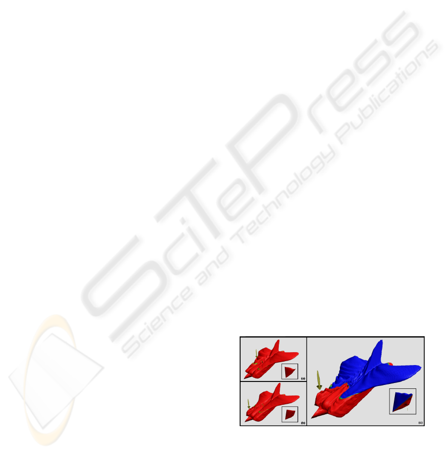
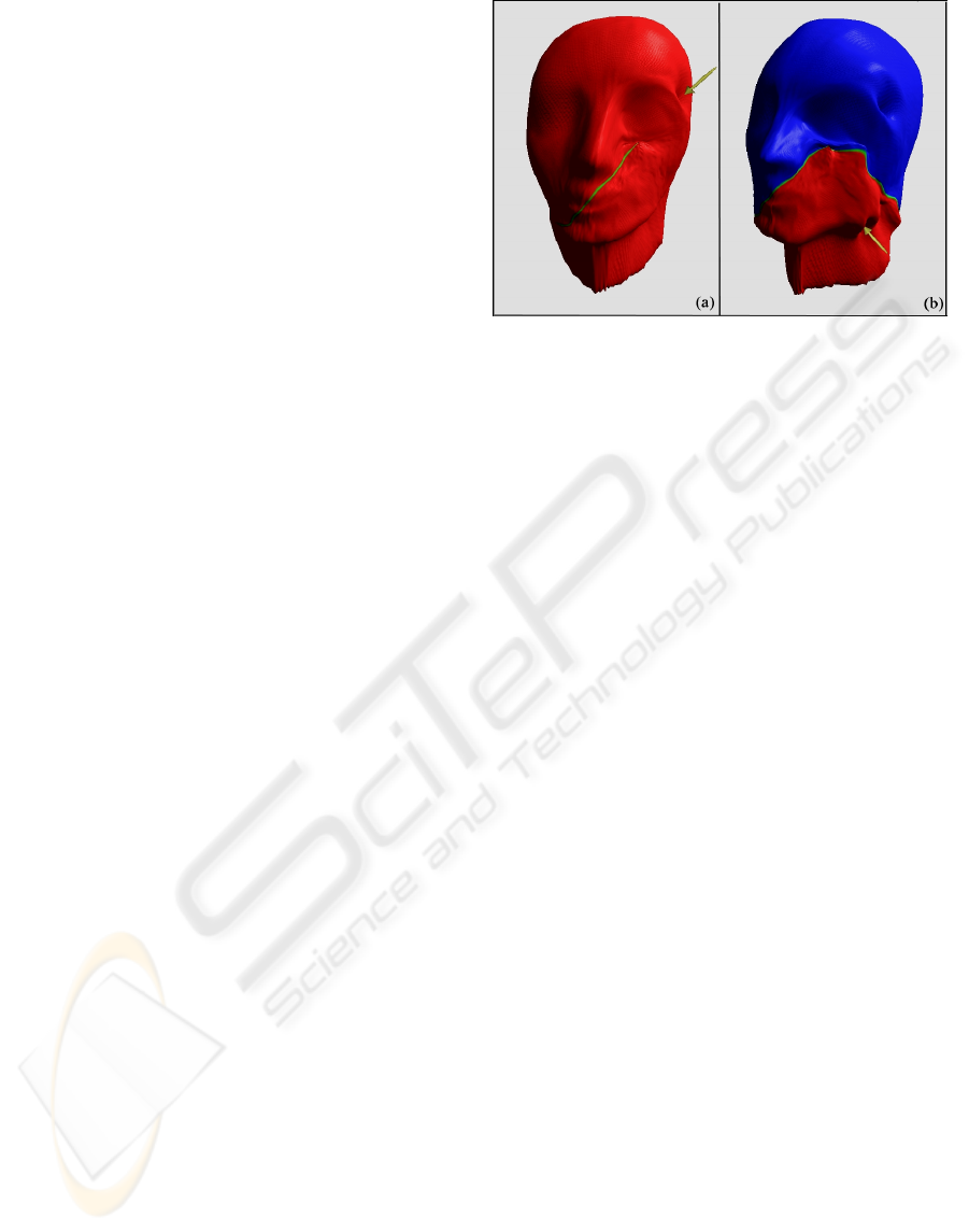
Figure 1.1: First (a) and second (b) peers deforming a
sample deformable model. (c) Colors red and blue denote
domains of different peers in a collaborative deformation.
In this paper, we are presenting a method for
deformations on closed surfaces over a peer-to-peer
network architecture (Figure 1.1).
121
Sumengen S., Tolga Eren M., Yesilyurt S. and Balcisoy S. (2007).
REAL-TIME DEFORMABLE OBJECTS FOR COLLABORATIVE VIRTUAL ENVIRONMENTS.
In Proceedings of the Second International Conference on Computer Graphics Theory and Applications - AS/IE, pages 121-128
DOI: 10.5220/0002080001210128
Copyright
c
SciTePress

2 RELATED WORK
2.1 Collaborative and Distributed
Network Virtual Environments
DIVE (Hagsand, 1996) is one of the first Distributed
Virtual Environments that allows participants to
collaborate in a 3D virtual world which facilitates
audio, video and text transmission for
communication and interaction within the VE.
Similarly, NPSNET (Macedonia, Zyda et al., 1994)
is designed for military training and simulation for
networked environments using Distributed
Interactive Simulation Standard (DIS). MASSIVE is
a VR conferencing system especially used for public
participation and performance (Benford, Greenhalgh
et al., 2001). VLNET allows multiple users
represented by 3D virtual human actors to interact
with each other and enables third parties to view the
shared virtual environment from the Web using
VRML(Thalmann, Babski et al., 1997).
There are only a few systems that in particularly
deal with the significance of physical simulation in
collaborative virtual environments. A recent work by
Jorissen (Jorissen and Maarten Wijnants, 2005),
gives a detailed survey on state of the art of dynamic
interactions and physical simulations in CVE’s.
Jorissen et al. introduces a collaborative virtual
environment, where the object-object interaction is
allowed in addition to avatar-object and avatar-
avatar interactions using a non-commercial physics
engine.
There are few attempts to introduce deformable
objects into CVE’s: Dequidt et al. (Dequidt, Grisoni
et al., 2005) propose a system based on ghost objects
to handle network latency. Ghost objects are
associated to objects manipulated over the network
and introduced into the client side to perform
physical simulations asynchronously at each user.
Collaborative Haptics Environments are also
introduced to handle surgical training and
simulations (Xiaojun, Bogsanyi et al., 2003). As
haptic rendering must be performed at simulation
rates higher than 1 KHz, most systems require
dedicated hardware running on real-time operating
systems (Zhou, Shen et al., 2004). Goncharenko et
al. (Goncharenko, Svinin et al., 2004) report a
distributed and collaborative haptic visualization of
a 1-DOF crank model only possible on Intranets.
They used a dedicated haptic communication library
to satisfy real-time communication requirements of
haptic rendering on a client-server architecture
connected through Ethernet.
2.2 Deformable Objects
Visualization of object deformations is an important
research area for over two decades with a large span
of applications such as cloth, tissue modeling and
virtual surgery. One set of approaches on the
visualization of deformable models is non-physical
and purely geometric techniques, most of which is
classified as Free-Form-Deformations (Sederberg
and Parry, 1986). Physics based approaches gained a
popular attention by enabling cloth animations
(Terzopoulos, Platt et al., 1987). Cloth animation is
an extensive research area covering wide range of
issues from physical simulation to collusion
detection (Volino and Magnenat-Thalmann, 2006).
Early examples of cloth animation using a linear
model based on energy minimization, and
continuing approaches using explicit integration
schemes, are suffering from stability issues for large
body deformations. Baraff and Witkin (Baraff and
Witkin, 1998), introduced an implicit integration
scheme for stable simulations using large time steps.
On the other hand, real-time simulation of
deformable models is an other challenge, and linear
mass-spring models introduced at first (Desbrun,
Peter Schröder et al., 1999). As an alternative,
Boundary Element Method is introduced, which is
inspired by Finite Element Method (FEM), however,
considers only the surface of the model (James and
Pai, 1999). Non-linear FEMs are not suitable for
real-time simulations since they are computationally
intensive, so deformable object simulations in virtual
environments continued to use improved mass-
spring models (Kang and Cho, 2002). Also, pre-
computed models for real-time dynamic
deformations are considered (Nikitin, Nikitina et al.,
2002). Since medical applications require real-time
and accurate simulations some approaches used
FEM to parameterize the mass-spring model to
improve accuracy (Choi, Sun et al., 2004).
3 NETWORK DEFORMABLE
OBJECTS
Our method applies a collaborative deformation on a
linear membrane model over network, which can be
used for simulation of deformable objects (tissue,
organ, cloth) in CVEs.
3.1 Geometric Model
The proposed approach requires a uniform
representation of the simulated structure. Restriction
GRAPP 2007 - International Conference on Computer Graphics Theory and Applications
122
on the genus of the model allows us to construct a
regular 2D grid that corresponds to the surface of the
model.
The surface of any convex polyhedron is
homeomorphic to a sphere and has Euler
characteristic of two. Homeomorphic spaces are
identical from the viewpoint of the topology
therefore genus zero surfaces preserve their
topological properties under spherical
parameterization and can be mapped onto a convex
regular polyhedron.
3.1.1 Mesh Representation
We have chosen Tetrahedron as the Domain for our
mesh representation, since it has four equilateral
triangular faces that can be represented as a 2D grid
having (2
n
+ 1) x (2
n+1
+ 1) nodes where, n is
positive integer determining the number of vertices
and will be referred as detail level (Figure 3.1).
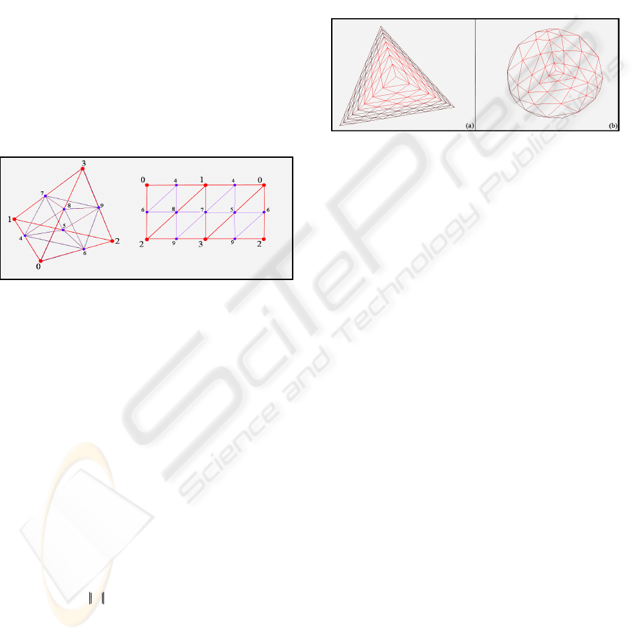
Figure 3.1: 2D Grid representation of a tetrahedron.
3.1.2 Mesh Generation
We propose an algorithm that converts irregularly
triangulated genus zero surfaces into a uniform mesh
with regular connectivity. Previous approach for
constructing regular meshes with fixed and simple
topology by Hoppe (Praun and Hoppe, 2003),
generates a spherical parameterization of the surface
and the domain. Surface, projected on the sphere,
mapped on to the domain, and unfolded to generate
the geometry image. We apply a similar procedure,
but we introduce a different technique for spherical
parameterization and model re-meshing. It allows
adjusting the tradeoff between face area uniformity
of the generated mesh, and preserving the accuracy
with the original mesh.
Given a triangle mesh M, the problem of
spherical parameterization is to form a continuous
invertible map φ : S→M from the unit sphere to the
mesh (Praun and Hoppe, 2003). Spherical
parameterization of both a regular tetrahedral
domain D and an irregular input mesh M are
necessary to generate Sphere to Mesh (S→M) and
Sphere to Domain (S→D) mappings that will allow
us to perform Mesh to Sphere and Sphere to Domain
(M→S→D) transformation.
Any convex polyhedron can easily be projected
onto a unit sphere (Figure 3.2) by switching to
spherical coordinate system (Θ, Φ, r) and setting a
unit radius for all vertices (Gnomonic Projection),
however translation between each mesh triangle and
spherical triangle might introduce a certain amount
of distortion.
Figure 3.2: Gnomonic Projection of a tetrahedron.
Previous approaches define a stretch norm to
measure the stretch efficiency and conclude that
minimizing the stretch norm is a non-linear
optimization problem (Sander, Snyder et al., 2001;
Praun and Hoppe, 2003). We attack this problem by
a modification of a well known technique used for
graph drawing. Graph drawing using force directed
placement methods, which are also called spring-
embedders, distributes vertices evenly in the frame
and minimize edge crossings while favoring
uniformity of the edge lengths (Fruchterman and
Reingold, 1991). Since we implemented a
deformable physics engine that can handle mass
spring systems efficiently, we introduce a variant of
spring-embedders for stretch optimization.
10,0,, <<≤≤∀×= CnNodesiixCx
ii
new
(3.2)
A spring-embedder model is generated from the
gnomonic projection of the domain. Every vertex
has a constant mass, and springs are introduced
between neighboring vertices. An external force
field (3.1) is applied from the center of the domain
that limits displacements of vertices on the unit
sphere.
Springs between the vertices tend to preserve
initial edge lengths and resist movements that
change the topology; however we need to establish a
tension on these springs to perform stretch
optimization.
We scale down the positions of the vertices that
are projected onto unit sphere (3.2), and an external
force which is applied continuously expands the
vertices onto the unit sphere again while producing a
tension on the springs. Stiffness parameters are
()
nNodesiixxf
i
iExternal
i
≤≤∀×−=
∧
0,1
(3.1)
REAL-TIME DEFORMABLE OBJECTS FOR COLLABORATIVE VIRTUAL ENVIRONMENTS
123
updated continuously to achieve an area uniform
tessellation over the unit sphere (Figure 3.3).
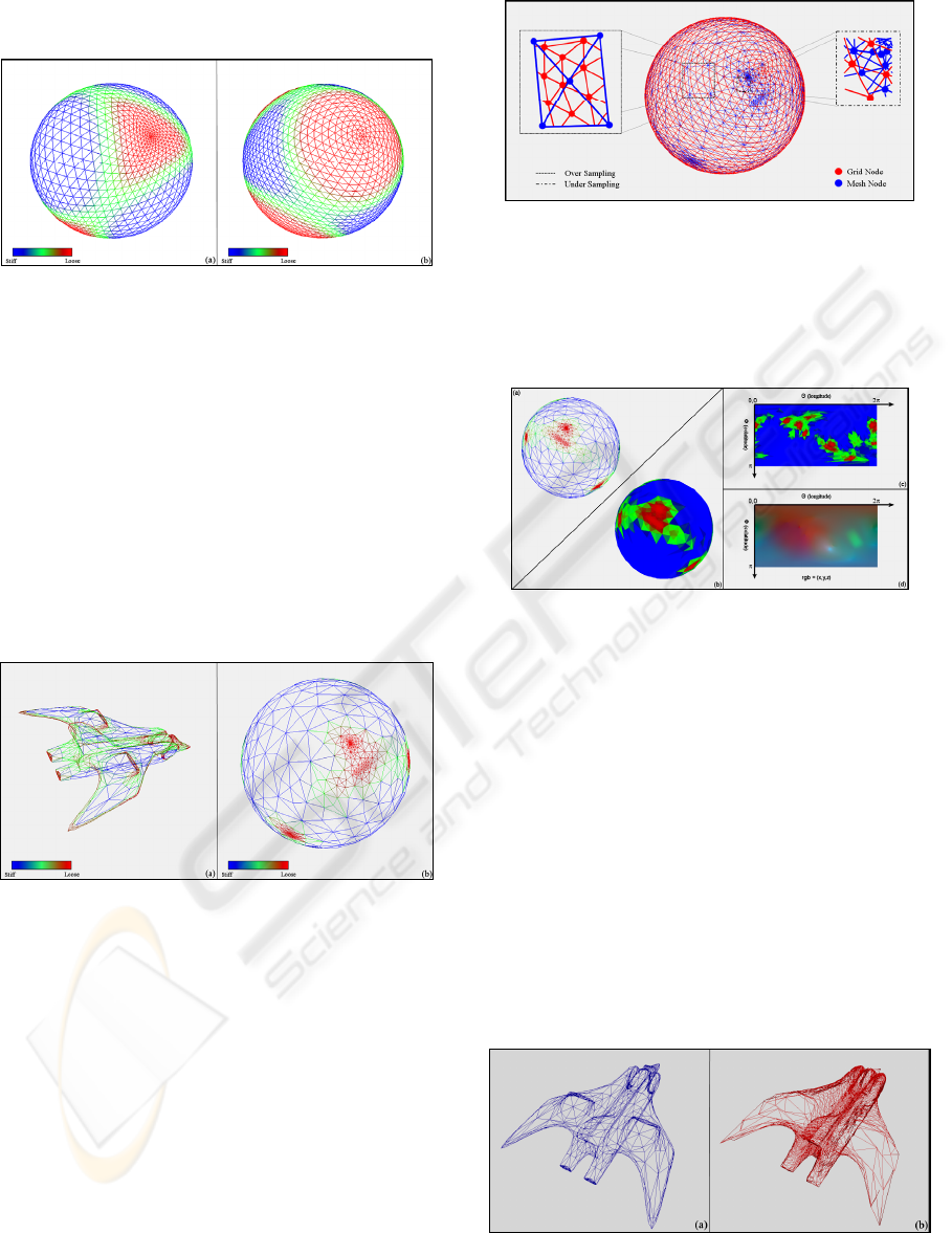
Figure 3.3: (a) Gnomonic Projection of Tetrahedron.
(b) Stretched Gnomonic Projection of Tetrahedron.
Our proposed force model is a feasible stretch
optimization technique for domain to sphere
mapping; however, it is insufficient for mesh to
sphere mappings where the projection of non-
convex polyhedron into a unit sphere results in edge
crossings and does not preserve initial surface
topology. We use a vertex displacement procedure
(3.3) which is similar to the relaxation method of
previous spherical parameterization approaches
(Alexa, 2002) to overcome this problem (Figure
3.4).
Figure 3.4: (a) Irregular Input Mesh. (b) Stretched
Gnomonic Projection of Input Mesh.
3.1.3 Model Re-meshing
Combining the spherical mappings mesh to sphere
(M→S) and sphere to domain (S→D) to derive
mesh to domain mapping (M→D), requires
intersection of the sets on the sphere. However,
transformed vertex coordinates of the mesh and
domain might not intersect on the sphere, and
vertices of the domain might fall inside of a mesh
facet. For each vertex of the domain, intersecting
face of the parameterized mesh should be found out
and 3D coordinates of domain vertex should be
computed by interpolating the vertices of the
intersecting face (Figure 3.5).
Figure 3.5: Intersecting Spherical Projections of
Tetrahedral Domain and Input Mesh.
Since computing the interpolated coordinates is
costly, we introduce a fast method taking advantage
of recent advances in graphics hardware using the
GPU and frame buffer objects.
Figure 3.6: Spherical projection of input mesh is, (a)
rendered as 3D wireframe, (b) 3D colored surface, (c) 2D
colored surface, and (d) 2D colored surface, where the
original positions of vertices are used as color
components.
Using OpenGL and programmable shaders
(GLSL), we render the faces of the parameterized
mesh onto the frame buffer using the two
dimensional spherical coordinates (Θ and Φ) of the
transformed vertices. Initial Cartesian coordinates
(x, y, and z) of the parameterized mesh vertices are
attached to color attributes (r, g, and b) at the vertex
shader, and inside of each face is filled with the
interpolated Cartesian coordinates at the fragment
level (Figure 3.6). Rendered image is then fetched
from the frame buffer as a 2D texture and used like a
lookup table to generate 3D coordinates of the
domain vertices.
Figure 3.7: Final comparison of (a) the input mesh with
1444 vertices, and (b) the resulting regular mesh with
8385 vertices.
.
,0,
,/
0
ithij
nNeighbors
j
iiji
xofneighbourjisx
nNodesii
nNeighborsxx
i
new
≤≤∀
=
∑
=
(3.3)
GRAPP 2007 - International Conference on Computer Graphics Theory and Applications
124
3.1.4 Subdivision Scheme using Convolution
Kernels
Subdivision methodology is appropriate for our
approach since it allows multi-resolution
representation of a surface and fast switching
between detail levels. It also favors numerical
stability , so it is highly suitable for physical
simulation of deformations using finite element and
finite difference methods.
We used a variant of butterfly subdivision
scheme (Zorin, Peter Schröder et al., 1996) that
generates a C
1
smooth triangular mesh. Modified
Butterfly Scheme is an interpolating subdivision
scheme, where the original vertices (control points)
are also the vertices of the refined surface and
surface is interpolating to a limit surface. This
behavior makes it possible to use surfaces with
different resolutions for graphical representation,
physical simulation, and network transmission,
without compromising the integrity of simulation
accuracy and the rendered image.
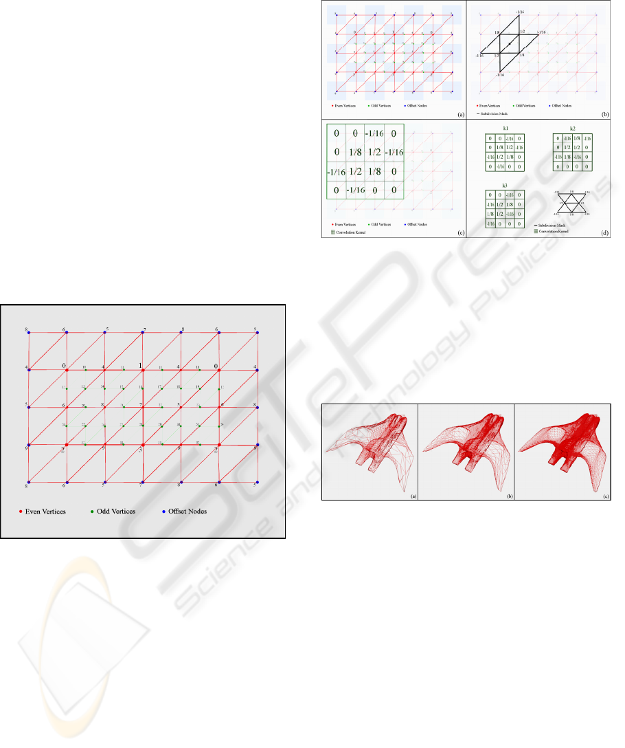
Figure 3.8: Modified 2D Grid Structure.
Given that we have a regular mesh representation as
a grid structure, we introduce some modifications
(Figure 3.8) to apply a fast and robust refinement
strategy using modified butterfly scheme. Taking
advantage of having a regular domain, we have no
boundary or crease vertices, but there are four
extraordinary vertices of valances three on the
corners of the tetrahedral domain. However, if we
duplicate the edges of these vertices, they can be
treated as regular vertices. Since the duplicate edges
are symmetric to existing edges, resulting odd
vertices will have same values. This modification
allows us to use the mask for interior odd vertices
with regular neighbors for all the grid nodes. We
also introduce offsets to 2D grid representation.
Offsets are the copies of grid nodes, assuring
existing neighboring properties and they are kept
updated before the convolution process.
Figure 3.9: (a) Modified 2D Grid Structure. (b)
Application of mask for interior odd vertices with regular
neighbors. (c) Equivalent convolution kernel. (d) Three
convolution kernels generated for three edges.
Having a 2D grid representation and a mask with
constant coefficients, odd vertices can be generated
by consecutive convolutions with three kernels
created by rotating the subdivision mask three times
(Figure 3.9).
Figure 3.10: Comparison of resulting mesh refined by
subdivision and rendered at different level of details: (a)
8335 vertices, (b) 33153 vertices, (c) 131841 vertices.
Necessity for the grid offsets arises from the
application of the mask to the grid boundaries, and
modified subdivision scheme requires first neighbors
of even vertices that are next to generated vertex.
Offset width does not change according to the grid
dimensions and time required for the update of the
offsets is negligible. After the convolution of the n
th
level subdivision surface three times, resulting 2D
grids are merged to generate n+1
th
level subdivision
surface having (2
n+1
+ 1) x (2
n+2
+ 1) nodes (Figure
3.10).
3.2 Physical Model
Physical simulation of deformable objects is an
extended research area, where several methods are
REAL-TIME DEFORMABLE OBJECTS FOR COLLABORATIVE VIRTUAL ENVIRONMENTS
125
present, varying from fast and simple methods
favoring speed and scalability, to much more
complex methods favoring accuracy and stability.
Linear methods such as mass-spring models for
dynamic deformations are suitable for use in real-
time applications; however, they are not capable of
handling large deformations and small time steps
which are required to guarantee stability (Desbrun,
Peter Schröder et al., 1999; Georgii and
Westermann, 2005). On the other hand, non-linear
models incorporating large viscoelastic and plastic
deformations are computationally intensive (Reddy,
2004), and despite their physical accuracy, real-time
simulation of large deformations is only possible
with massively parallel computers.
For the demonstration of the deformable object
on a collaborative virtual environment, we use a
real-time physical simulation of a uniform-tension-
membrane, based on linear finite-elements. We
introduced finite element discretization to form the
global stiffness matrix, which is updated frequently
to handle large deformations with enhanced
accuracy and we used Runge-Kutta-Fehlberg
method for integration to achieve bigger time steps
and improved stability (Baraff and Witkin, 2003).
3.2.1 Linear Finite-Element Model
Application of the finite-element method for the
wave equation (Bathe and Bathe, 1996; Reddy,
2004), describing the time-dependent small
deformations of a uniform-tension membrane results
in a standard system of equations (Hughes, 1987):
where, x is the normal deformation of each node, M
is the diagonal mass matrix,
external
f
is the external
force vector due to user interactions, B is the
diagonal damping matrix, and K is the stiffness
matrix. In our implementation, we separate normal
deformation and the velocity of each node to
improve the stability of the Runge-Kutta method
used to solve the linear system.
Namely, we have
and the resulting equation of motion:
The finite element method works well with an
arbitrary triangulation of a surface as well as
proposed regular grid structure. In our
implementation we apply the damping matrix
directly on the nodal velocities, so as to model a
permeable membrane placed in a liquid. In some
standard formulations, the damping is applied to
relative nodal velocities. The two yields in similar
solutions, however our implementation results in
simpler sparse structures and faster simulation times
via improved stability of nodal damping.
3.3 Network Model
There are several network topologies used for
Distributed Virtual Environments. Our approach is
implemented with a peer-to-peer architecture which
is operational on local and wide area networks. User
Datagram Protocol (UDP) is used for
communication, since speed and bandwidth
requirements are essential for a real time simulation
and have a greater priority over packet integrity.
Peers can run on different computers on the
network or can be started in the same application as
separate threads. We don’t introduce any dedicated
servers, and peer nodes are functioning as both
clients and servers. Every peer has a listening port
and address for incoming connection requests. The
peer which started to run CVE is required to act as a
master for coordinating partitioning of the
simulation. Partitioning occurs after sending a
request by a participant which selects a face on the
mesh and identifies it as the point of interest where
the peer is going to introduce an external force.
Participants can enter the CVE also as a viewer,
where they do not interact with the model, but can
observe the simulation.
3.4 Partitioning and Synchronization
of Physical and Geometric Models
through the Network
In our approach, partitioning the deformable object
and synchronizing among peers is an important
issue, since it enables collaboration in the virtual
environments with distributed computational load.
For an efficient communication and separation, we
introduce a quad tree based data structure over 2D
grid structure proposed on the previous sections.
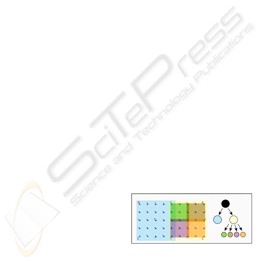
Figure 3.11: Sample tree structure for tetrahedral domain
having depth of two.
Quad-tree structure (Figure 3.11) is a natural
formation for the tetrahedral domain, and can be
divided hierarchically. Tree nodes are transferred
efficiently via network since a tree node contains a
external
fKxxBxM +−−=
&&&
(3.4)
vx =
&
(3.5)
external
fKxBvvM +−−=
&
(3.6)
GRAPP 2007 - International Conference on Computer Graphics Theory and Applications
126
range identifier which is actually the combination of
upper left and lower right node index numbers, and
state information of corresponding region as a 2D
array. Minimum depth level for the tree can be
adjusted to keep the packaged tree node size smaller
then the maximum packet size allowed by the
network protocol.
Domain divisions are designed upon a quad tree
based structure in the figure (Figure 3.11). While
dividing the domain into sub-domains, equivalence
of the number of shared grid nodes is an important
criterion. However, keeping the domain boundaries
shorter for an accurate synchronization of the
physical simulation is essential, and keeping the
fragmentation minimal for efficient network
transmission is also important.
At the beginning of the simulation, each client
starts to simulate the whole domain independently.
When a connection invoked, domain is partitioned
according to the points of interest where the forces
are applied by the clients. Nodes at the domain
boundaries are treated as boundary conditions, and
the dynamical simulation of the local domain
performed consequently at the each client.
4 RESULTS
Our graphical sub-system can efficiently handle very
large meshes, taking advantage of regular-mesh and
subdivision methodology as presented in the
previous chapters (Figure 4.1). Our system renders
meshes using the Phong shading model at interactive
frame rates (25 fps) with resolution up to 100K
polygons on an AMD Opteron 2.6 GHz PC equipped
with NVIDIA Quadro FX4500 GPU. We
implemented Phong shading model on the GPU.
Vertex positions are uploaded to texture memory
and vertex normals are computed on the fly using
texture lookups.
The proposed network communication model
can handle synchronous simulation among two peers
of a surface up to 10K vertices over the local area
network. This level has a bandwidth requirement of
20 M Bits per second without any compression.
We also tested the performance of the system by
comparing computational load and number of
simulated nodes. Our deformation engine can handle
multi-resolution meshes up to 30K nodes, and
maintains interactivity at less than %30 CPU
utilization. Partitioning the domain between clients
reduces computational load by 45% on the average,
and increases the running speed by a factor of 1.8,
depending on the partitioning ratio.
Figure 4.1: (a) One peer and (b) two-peers collaborative
network deformation of a sample model having a regular
mesh structure.
5 CONCLUSION
We have proposed a new technique for deformable
body simulations in the field of collaborative virtual
environments and introduced several improvements
over the methods we adopted. We found that
adaptive refinement and multilevel meshing
strategies are promising research domains that can
be further exploited for increased network efficiency
and better physical accuracy for CVE’s.
Furthermore, we showed that the partitioning of
physical simulation domain has a considerable effect
on performance, and makes real-time simulation
possible in scenarios where only one peer is
incapable of handling the computational load.
As future work, we consider on the fly
compression which might significantly reduce the
bandwidth requirement but can degrade overall
performance because of the additional computational
cost. Optimization of the system for the Internet is
out of the scope of this paper, but it is safe to predict
that the network lag on public networks will have an
impact on performance. Our method needs to be
optimized for the Internet, and tested over large
physical distances to overcome possible negative
network effects.
REFERENCES
Alexa, M. (2002). Recent Advances in Mesh Morphing,
Blackwell Synergy. 21: 173-196.
Baraff, D. and A. Witkin (1998). Large steps in cloth
simulation. Proceedings of the 25th annual conference
on Computer graphics and interactive techniques,
ACM Press.
REAL-TIME DEFORMABLE OBJECTS FOR COLLABORATIVE VIRTUAL ENVIRONMENTS
127

Baraff, D. and A. Witkin (2003). Physically based
modeling. Proceedings of the conference on
SIGGRAPH 2003 course notes. Los Angeles, CA,
ACM Press.
Bathe, K.-J. and K.-J. Bathe (1996). Finite element
procedures. Englewood Cliffs, N.J., Prentice Hall.
Benford, S., C. Greenhalgh, et al. (2001). "Collaborative
virtual environments." Commun. ACM 44(7): 79-85.
Choi, K.-S., H. Sun, et al. (2004). "Deformable simulation
using force propagation model with finite element
optimization." Computers & Graphics 28(4): 559-568.
Dequidt, J., L. Grisoni, et al. (2005). Collaborative
interactive physical simulation. Proceedings of the 3rd
international conference on Computer graphics and
interactive techniques in Australasia and South East
Asia %@ 1-59593-201-1. Dunedin, New Zealand,
ACM Press: 147-150.
Desbrun, M., Peter Schröder, et al. (1999). Interactive
animation of structured deformable objects.
Proceedings of the 1999 conference on Graphics
interface '99. Kingston, Ontario, Canada, Morgan
Kaufmann Publishers Inc.
Fruchterman, T. and E. Reingold (1991). "Graph Drawing
by Force-directed Placement." Software - Practice and
Experience 21(11): 1129-1164.
Georgii, J. and R. Westermann (2005). "Mass-spring
systems on the GPU." Simulation Modelling Practice
and Theory 13(8): 693-702.
Goncharenko, I., M. Svinin, et al. (2004). Cooperative
Control with Haptic Visualization in Shared Virtual
Environments. Proceedings of the Information
Visualisation, Eighth International Conference on
(IV'04) - Volume 00, IEEE Computer Society.
Hagsand, O. (1996). "Interactive multiuser VEs in the
DIVE system." Multimedia, IEEE 3(1): 30-39.
Hughes, T. J. R. (1987). The finite element method : linear
static and dynamic finite element analysis. Englewood
Cliffs, N.J., Prentice-Hall.
James, D. L. and D. K. Pai (1999). ArtDefo: accurate real
time deformable objects. Proceedings of the 26th
annual conference on Computer graphics and
interactive techniques, ACM Press/Addison-Wesley
Publishing Co.
Jorissen, P. and Z. M. W. L. Maarten Wijnants (2005).
"Dynamic Interactions in Physically Realistic
Collaborative Virtual Environments." IEEE
Transactions on Visualization and Computer Graphics
%@ 1077-2626 11(6): 649-660.
Kang, Y.-M. and H.-G. Cho (2002). Complex deformable
objects in virtual reality. Proceedings of the ACM
symposium on Virtual reality software and
technology. Hong Kong, China, ACM Press.
Macedonia, M. R., M. J. Zyda, et al. (1994). "NPSNET- A
network software architecture for large-scale virtual
environments." Presence: Teleoperators and Virtual
Environments 3(4): 265-287.
Nikitin, I., L. Nikitina, et al. (2002). Real-time simulation
of elastic objects in virtual environments using finite
element method and precomputed Green's functions.
Proceedings of the workshop on Virtual environments
2002. Barcelona, Spain, Eurographics Association.
Peter Schroder, D. Z. (2000). SIGGRAPH Full Day
Course: Subdivision for Modeling and Animation.
Praun, E. and H. Hoppe (2003). "Spherical
parametrization and remeshing." 22(3): 340-349.
Reddy, J. N. (2004). An introduction to nonlinear finite
element analysis. Oxford ; New York, Oxford
University Press.
Sander, P. V., J. Snyder, et al. (2001). Texture mapping
progressive meshes. Proceedings of the 28th annual
conference on Computer graphics and interactive
techniques, ACM Press.
Sederberg, T. W. and S. R. Parry (1986). Free-form
deformation of solid geometric models. Proceedings of
the 13th annual conference on Computer graphics and
interactive techniques, ACM Press.
Terzopoulos, D., J. Platt, et al. (1987). Elastically
deformable models. Proceedings of the 14th annual
conference on Computer graphics and interactive
techniques, ACM Press.
Thalmann, D., C. Babski, et al. (1997). "Sharing VLNET
worlds on the Web." Computer Networks and ISDN
Systems 29(14): 1601-1610.
Volino, P. and N. Magnenat-Thalmann (2006). Resolving
surface collisions through intersection contour
minimization, ACM Press. 25: 1154-1159.
Xiaojun, S., F. Bogsanyi, et al. (2003). A heterogeneous
scalable architecture for collaborative haptics
environments.
Zhou, J., X. Shen, et al. (2004). Haptic tele-surgery
simulation.
Zorin, D., Peter Schröder, et al. (1996). Interpolating
Subdivision for meshes with arbitrary topology.
Proceedings of the 23rd annual conference on
Computer graphics and interactive techniques, ACM
Press.
GRAPP 2007 - International Conference on Computer Graphics Theory and Applications
128
