
ADAPTIVE CUBE TESSELLATION FOR TOPOLOGICALLY
CORRECT ISOSURFACES
Francisco Velasco, Juan Carlos Torres, Alejandro Le
´
on and Francisco Soler
ETSIIT, University of Granada, C/ Periodista Daniel Saucedo Aranda s/n, Granada, Spain
Keywords:
Volume Visualization, Isosurfaces, Marching Cubes, Marching Tetrahedra.
Abstract:
Three dimensional datasets representing scalar fields are frequently rendered using isosurfaces. For datasets
arranged as a cubic lattice, the marching cubes algorithm is the most used isosurface extraction method.
However, the marching cubes algorithm produces some ambiguities which have been solved using different
approaches that normally implying a more complex process. One of them is to tessellate the cubes into tetra-
hedra, and by using a similar method (marching tetrahedra), to build the isosurface. The main drawback of
other tessellations is that they do not produce the same isosurface topologies as those generated by improved
marching cubes algorithms. We propose an adaptive tessellation that, being independent of the isovalue, pro-
duces the same topology for all the cases. Moreover the tessellation allows isosurface to evolve continuously
when the isovalue is changed smoothly without extra computations.
1 INTRODUCTION
A popular representation of digitized volumes is a
regular lattice of points which represent the digitized
samples. This set of samples can be used directly
or can be previously prefiltered to obtain a reduced
dataset. The most used lattice for some fields is a grid
of cubic cells. This representation is easily obtained
from a computerized axial tomography (CAT scan) or
by magnetic resonance imaging (MRI). In both cases
several 2D images are obtained that can be easily rep-
resented by a 3D grid in which every corner represents
a point sample.
Thus, a volume can be represented by the equa-
tion:
( {(x, y, z, γ)} , F(x, y, z) : R
3
→ Γ ) (1)
where {(x, y, z, γ)} is the set of samples in the property
domain Γ, and F(x, y, z) : R
3
→ Γ is the function that
approximates values between samples.
There are several methods to visualize a volume
represented by a grid: by slices, direct visualization
(Levoy, 1990), or by means of isosurface extraction.
By this later method, the focus of this paper, a thresh-
old value γ
0
is set and an isosurface F(x, y, z) = γ
0
is
built and rendered as volume visualization. Usually
γ
0
is also called isovalue. Several parts of the vol-
ume can be rendered by modifying γ
0
. In this method
F(x, y, z) must be extended outside the samples, usu-
ally as a linear interpolation function. The classi-
cal algorithm in this category is the marching cubes
method (Lorensen and Cline, 1987). This method ex-
tends F as a trilinear interpolation function and builds
the isosurface cube by cube, marching through all the
cubes into the grid of cubic cells.
Every cell is classified, by comparing its eight ver-
tex values with the threshold γ
0
, as belonging to one of
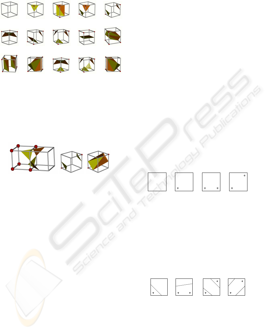
the fifteen possible equivalence classes. Every class
(or case) has an isosurface represented as a triangle
mesh. The entire isosurface to be rendered is obtained
by joining the pieces of isosurface generated for every
cube. Figure 1 shows the fifteen cases with their inte-
rior triangle meshes.
However, this method is ambiguous in some
topologycal aspects, the ambiguity has been well
studied in (Wilhelms and Gelder, 1990; Nielson and
Hamann, 1991; Montani et al., 1994; Chernyaev,
1995; Cignoni et al., 2000; Lopes and Brodlie, 2003;
Nielson, 2003). For instance, figure 2-a shows that
a crack arises on the isosurface between the two
212
Velasco F., Carlos Torres J., León A. and Soler F. (2007).
ADAPTIVE CUBE TESSELLATION FOR TOPOLOGICALLY CORRECT ISOSURFACES.
In Proceedings of the Second International Conference on Computer Graphics Theory and Applications - GM/R, pages 212-219
DOI: 10.5220/0002073602120219
Copyright
c
SciTePress
Case 0 Case 1 Case 2 Case 3 Case 4
Case 5 Case 6 Case 7 Case 8 Case 9
Case 10 Case 11 Case 12 Case 13 Case 14
Figure 1: Well known cell cases in marching cubes method.
cells; figure 2-b shows the triangle mesh proposed by
marching cubes for the Case 4 however, the one in fig-
ure 2-c may also be possible. To find out which one is
correct we need information about the interior of the
cell.
(a) (b) (c)
Figure 2: Examples of handicaps of marching cubes.
Lopes, Brodlie and Nielson in (Lopes and Brodlie,
2003; Nielson, 2003) solve the ambiguity studying
the interior of the faces and the interior of the cell
using the trilinear interpolation equation to define the
property variation. As a consequence, the number of
different equivalence classes is increased to 31 and 57
cases respectively.
Other authors (Zhou et al., 1995; Gueziec and
Hummel, 1995; Chan and Purisima, 1998; Gerstner
and Pajarola, 2000) solve the ambiguity using a tes-
sellation of the cell into tetrahedra and building the
isosurface by marching tetrahedra (Payne and Toga,
1990). This method is similar to marching cubes but
based on a tetrahedron instead of a cube, with the
added advantage that, in this method, there are no am-
biguities as it is well known and only has 3 equiva-
lence classes.
However, for many classes of extended march-
ing cubes (EMC)(Lopes and Brodlie, 2003; Nielson,
2003), the topology of the isosurface which is built
by EMC is not the same as the topology of the isosur-
face built by marching tetrahedra from tessellations in
other published works.
In this paper we propose a tessellation of cells into
tetrahedra which produces the same isosurface topol-
ogy as the one that would be extracted by the extended
marching cubes methods.
The next section analyses the sources of ambigu-
ity in a cube. Section three presents some tessellations
used to obtain tetrahedra from cubes. In section four
we put forth our proposal of tessellation. The paper
ends with a section presenting the results and the con-
clusions.
2 CORRECT ISOSURFACES
In order to determine the correct topology for an iso-
surface we have to study the interpolation function F,
which is a trilinear interpolation function. For a more
exhaustive study the paper by Nielson (Nielson, 2003)
may be consulted.
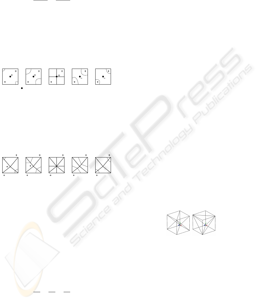
Let us begin analyzing a cube face. Taking into ac-
count that every face vertex can be positive (its value
is greater than the isovalue) or negative and that a face
has four vertices, there are 2
4
= 16 possible configu-
rations of a face, however by rotation or by comple-
mentation (positive/negative), there are only 4 equiv-
alence classes (see figure 3).
v00
v01
v10
v11
Case 0 Case 1 Case 2 Case 3
Figure 3: Cases for a face.
Assuming a linear variation along the edges, it is
easy to prove that Case 0 does not have isocurve and
Cases 1 and 2 have the two isocurve topologies shown
in figure 4. However, Case 3 has 2 possible isocurve
topologies as is shown in figure 4 depending on which
vertices can be connected by a line without intersect-
ing the isocurves, the negative ones (case 3-a) or the
positive ones (case 3-b).
Case 1 Case 2 Case 3-a Case 3-b
Figure 4: Isocurves for a face.
To discover which one is the correct topology we
have to compute the face saddle point, the point where
one topology changes into another. This point is com-
puted by using the function that interpolates the inte-
rior of the face, which is the bilinear interpolation:
F
face
(x, y) = axy+ bx+ cy+ d (2)
ADAPTIVE CUBE TESSELLATION FOR TOPOLOGICALLY CORRECT ISOSURFACES
213
The face saddle point is calculated by making the
partial derivates, with respect to x and y, equal zero:
∂F
face
∂x
=
∂F
face
∂y
= 0 (3)
and its value is computed using the equation 2.
So, we have a 5
th
point which can be positive or
negative and allows us to choose the correct topology
of the isocurve as it is shown in figure 5. The face
saddle point becomes the inflection point between the
two configurations; it is a contact point when the iso-
value is equal to the face saddle point value (central
image in figure 5).
Saddle point together with its sign
Figure 5: An isocurve which is continuously moved when
the isovalue changes.
The face saddle point (FSP), when present and
when it is inside the face, can be used to tessellate
it into 4 triangles, so the correct topology is directly
obtained by processing the triangles instead of the
square (see figure 6).
Figure 6: The isocurve topology is preserved when the
square is tessellated into triangles.
If the face saddle point is not present or is outside
the face, it can be shown that the face will be always
classified as belonging to Cases 0, 1 or 2 (figure 3),
which are not ambiguous.
For the interior of the cube the process is similar:
the body saddle points need to be computed.
The function that interpolates the interior of the
cube is the trilinear interpolation:
F(x, y, z) = axyz+ bxy+ cyz+ dzx+ ex+ fy+ gz+ h
(4)
The body saddle point (BSP) is also obtained by
making 0 the three partial derivates:
∂F
∂x
=
∂F
∂y
=
∂F
∂z
= 0 (5)
The result of this equation system gives two possi-
ble body saddle points which are used to solve the am-
biguities and choose the correct topology for the iso-
surface. The body saddle points are inflection points
between the different configurations for an ambiguous
cell. In this way, we can use the body saddle points,
when they are present and they are inside the cell, to
tessellate the cube into tetrahedra. The correct topol-
ogy of the isosurface can be obtained by marching
tetrahedra as will be shown in sections 4 and 5.
All the possible topologies, numbered following
Lopes’ methodology in (Lopes and Brodlie, 2003),
are shown in figure 7. The first number defines the
case taking into account the configuration of positive
and negative vertices, the second number defines dif-
ferent solutions for ambiguous faces, and the third one
defines different solutions for the ambiguous body.
The case 0, without isosurface, is not shown. Niel-
son presents more cases in (Nielson, 2003), this is
due to the use of a different equivalence relationship,
but many of the cases are equivalents according to the
Lopes’ equivalence relationship.
These topologies can be easily obtained by march-
ing tetrahedra with the adequate tessellation. The next
section shows related works on tessellations and sec-
tion 4 puts forth our proposal for the tessellation.
3 PREVIOUS TESSELATIONS
The marching tetrahedra method (Payne and Toga,
1990) for isosurface building is similar to the march-
ing cubes method (Lorensen and Cline, 1987):
This method is non ambiguous by assuming a lin-
ear interpolation along the edges. Thus, by tessellat-
ing a cell into tetrahedra (figure 8 shows the most
used tessellations) the ambiguity problem could be
solved as can be appreciated in (Payne and Toga,
1990; Gueziec and Hummel, 1995).
(a) (b)
Figure 8: Two possible tessellations for the basic case.
However, these studies do not take into account
that the property variation along a diagonal of a cube
face is not linear, but quadratic, so that diagonal which
is taken as a tetrahedron edge could have two inter-
sections with the isosurface and not only one. Zhou
et al. (Zhou et al., 1995) study this question and de-
fine a new way to build isosurfaces inside tetrahedra
taking into account the quadratic variation of proper-
ties along diagonal edges, but there are 59 different
cases! And moreover the method does not produce
topologies like that of 4.1.2 in figure 7.
GRAPP 2007 - International Conference on Computer Graphics Theory and Applications
214
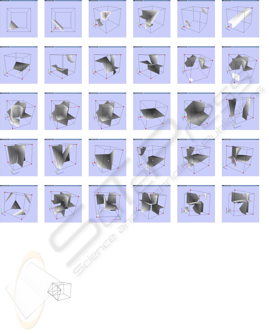
1 2 3.1 3.2 4.1.1 4.1.2
5 6.1.1 6.1.2 6.2 7.1 7.2
7.3 7.4.1 7.4.2 8 9 10.1.1
10.1.2 10.2 11 12.1.1 12.1.2 12.2
13.1 13.2 13.3 13.4 13.5.1 13.5.2
Figure 7: Isosurface topologies for a cell.
Chan and Purisima (Chan and Purisima, 1998) de-
fine a different tessellation (see figure 9) by defining
tetraedra between adjacent cells, but the method does
not produce topologies like that of 13.5.1 in figure 7.
Figure 9: Chan’s tessellation.
Recent studies have improved this method. Treece
et al. (Treece et al., 1998) reduce the number or
triangles by clustering tetrahedra vertices which pre-
serves the topology, the triangles built are more regu-
lar, so the Gouraud shading is improved. Gerstner et
al. (Gerstner and Pajarola, 2000) achieve a multires-
olution tessellation by a recursive bisection of some
tetrahedron in two. They take into account several
critical points to preserve or not the topology in ac-
cordance with certain criteria. Both studies start from
a tessellation that does not produce all the topologies
of figure 7.
Chiang et al. (Chiang and Lu, 2003) propose a
progressive simplification of tetrahedral meshes by
using a contour tree, a data structure that represents
the relations between connected components of the
isosurfaces embedded in a volume dataset. Since the
structure used includes critical points, the simplifica-
tion preserves the topology. The authors focus on an
irregular grid, however their method can be also ap-
plied to regular grids.
Our proposal produces a tessellation that pre-
serves all the topologies of figure 7 and can be used
as an initial tessellation to the work of Chiang.
ADAPTIVE CUBE TESSELLATION FOR TOPOLOGICALLY CORRECT ISOSURFACES
215
4 OUR PROPOSAL
We propose to carry out an adaptive tessellation of
every cell into tetrahedra in such a way that:
1. The tessellation must be isovalue independent in
order to compute it just once, avoiding extra com-
putations every time that the isovalue is changed.
2. The isosurface built inside the cell by joining the
pieces of isosurfaces built from every tetrahedron
of the tessellation has to be topologically equiva-
lent to the isosurface built by using the extended
marching cubes already commented in section 2
and in figure 7.
3. The isosurface has to move smoothly when the
isovalue changes smoothly.
It will be done by taking into account the face and
body saddle points.
We will use a basic tessellation which is valid for
all non ambiguous cell configurations, that is to say,
it is valid for those cells without face saddle points
nor body saddle points. Then, this basic tessellation
will be modified when face or body saddle point exist.
These special points will be tetrahedra vertices and
will be located at their exact position to improve the
isosurface accuracy.
Basic case: 0 ambiguous faces and 0 body saddle
points (Case 0-0)
The basic case corresponds to cells without ambigu-
ous faces and without body saddle points. This kind
of cell is tessellated as shown on figure 8-a. This tes-
sellation produces 6 tetrahedra. Note that it is possible
to build a tessellation which produces just 5 tetrahe-
dra (see figure 8-b) but it is less homogeneous than the
one proposed, because it implies the use of 2 possible
symmetric tessellations depending on the position of
the cell as can be deduced in figure 8-b. In figure 10
you can see an example of this case where the iso-
value is smoothly changed.
Case 0-1
This case corresponds to cells without ambiguous
faces and just 1 body saddle point. This kind of cell is
tessellated as is shown in figure 11-a where the BSP
is the central point. In order to see it clearly, one
must look at figure 11-b where is shown the tessella-
tion which corresponds to a face, the other 5 faces are
tessellated in a similar way. As such, this tessellation
produces 12 tetrahedra.
All the tetrahedra share the body saddle point, so
the topology around this point is preserved (see figure
12). In this figure the isovalue changes smoothly and
so, the isosurface is moved smoothly from one topol-
ogy to another.
Figure 10: Isosurface of 1 component.
(a) (b)
Figure 11: Tessellation for the case 0-1.
Figure 12: Isosurface in a cell within 1 body saddle point.
The right bottom image is the same case than the left bottom
one, only the point of view changes.
Case 1-0
In this case, there is just 1 ambiguous face and 0 body
saddle points. In this case, we introduce an internal
point at (0.5, 0.5, 0.5) together with its property value.
As such, the cell is tessellated as is shown in figure
GRAPP 2007 - International Conference on Computer Graphics Theory and Applications
216
13-a where the FSP is bottom face central point. The
ambiguous face is tessellated as shown in figure 13-
b and the non ambiguous faces are tessellated as in
figure 11-b.
(a) (b)
Figure 13: Analisis for the case 1-0.
Cases x-0 and x-1
As we have already shown, cases x-0 are converted
into cases x-1. That is to say, x ambiguous faces (1 ≤
x ≤ 6) and 1 internal point. These cases are tessellated
as figure 13-b for ambiguous faces and as figure 11-
b for unambiguous faces. This tessellation produces
12+ 2x tetrahedra.
In these cases the topology is preserved around the
face and body saddle points as can be easily observed
by the fact that all the tetrahedra of an ambiguous face
share the face saddle point and all the tetrahedra from
the tessellation share the body saddle point (see fig-
ures 14, 15 and 16).
Figure 14: Isosurface on an ambiguous face.
Case 0-2
This represents a cell with no ambiguous faces and
2 body saddle points. These two body saddle points
form an edge
B1B2. Using this edge and the 6 edges
of the cuboid formed by the vertices V1, V5, V4, V6,
V2, V3 (see figure 17-a), 6 tetrahedra are built (see
Figure 15: Isosurface on 2 opposite ambiguous faces.
Figure 16: Isosurface in a cell with 6 ambiguous faces but
no body saddle points.
figure 17-b). The back, left and bottom faces (which
share V0) are tessellated as it was shown in figure 11-
b but using B1 as the pyramid vertex (the body sad-
ADAPTIVE CUBE TESSELLATION FOR TOPOLOGICALLY CORRECT ISOSURFACES
217
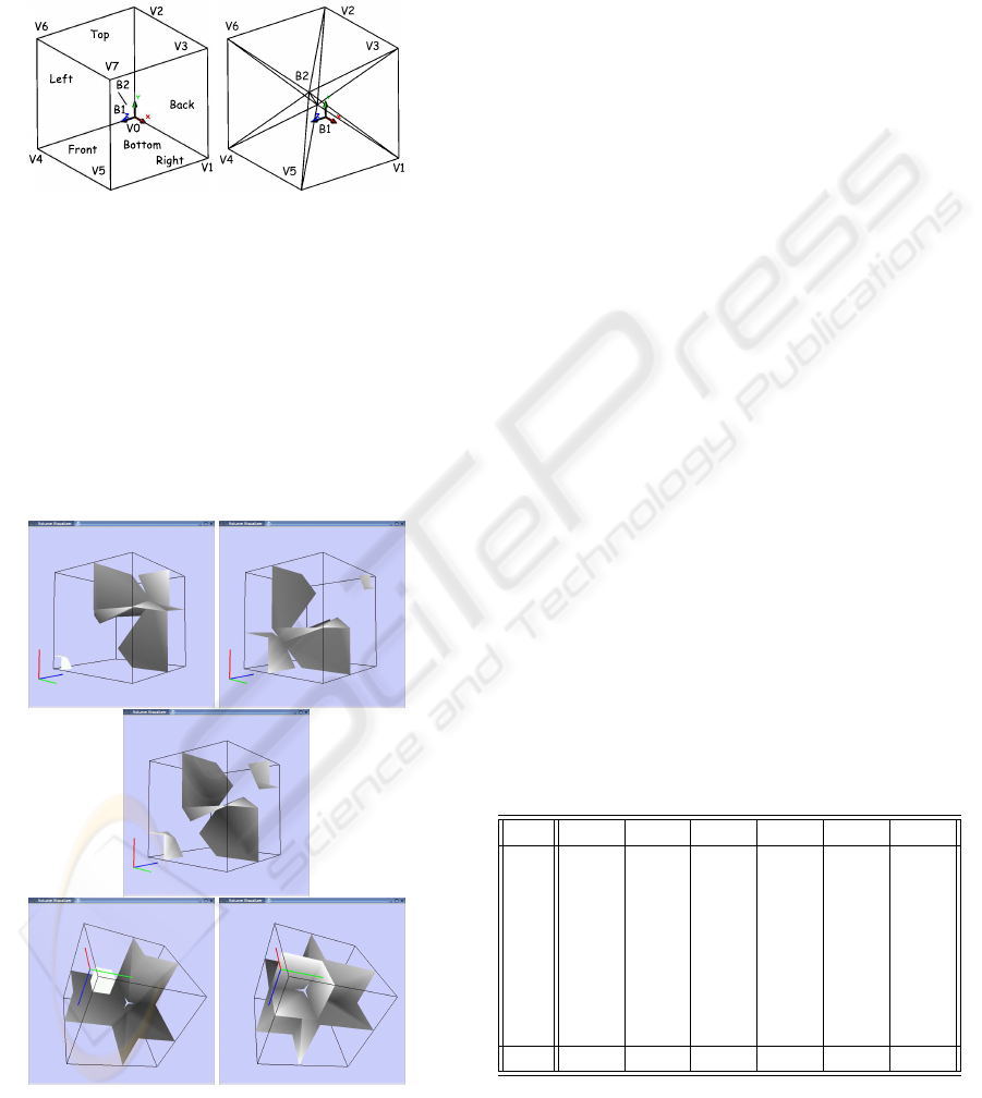
dle point nearest to the cell origin). The front, right
and top faces (which share V7) are tessellated in the
same way but using B2 as the pyramid vertex, the
other body saddle point. This tessellation produces
18 tetrahedra.
(a) (b)
Figure 17: Analisis for the case 0-2.
Case x-2
The tessellation according to this case is carried out
as the one shown for the case 0-2 but the ambiguous
faces are tessellated as it was shown in figure 13-b in-
stead of the tessellation shown in figure 11-b. This
tessellation produces 18 + 2x tetrahedra. The topol-
ogy is also preserved in theese cases as can be seen in
figure 18.
Figure 18: Isosurface in a cell with 2 body saddle points.
The images at the 3
rd
line show the first and last cases of
the 1
st
line from other point of view. The image of the 2
nd
line shows an intermediate case.
5 RESULTS AND CONCLUSIONS
The proposed method has been tested by using a
cell with configurations for all the cases of improved
marching cubes. In this section we show the most rep-
resentative ones. Every example is shown using dif-
ferent isovalues on the basis of the same cell, where
one can see how the isosurface changes smoothly
when the isovalue is slightly changed.
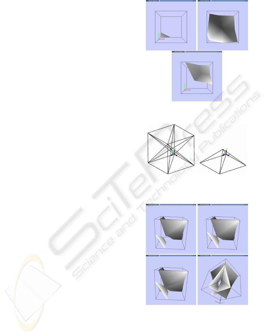
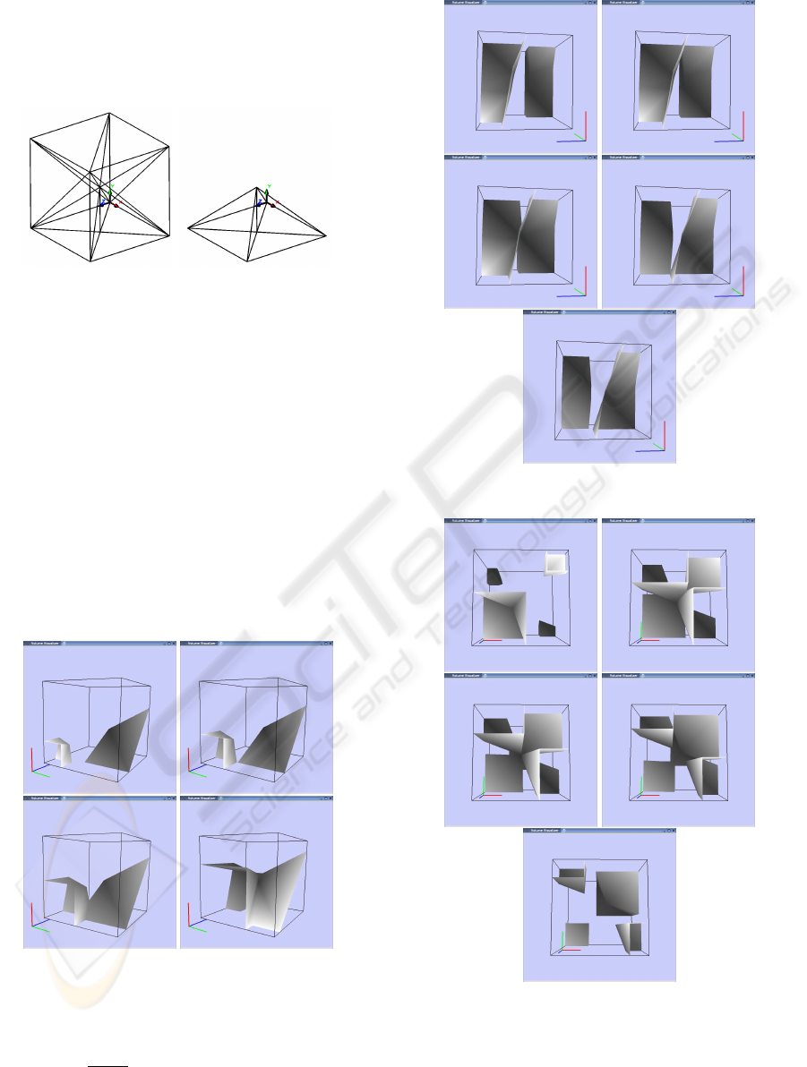
Example 1 (figure 10): A configuration with 1
component on the basis of the simpliest tessellation.
Example 2 (figure 12): By modifying the iso-
value from 26 to 23 we can see how an isosurface of 2
components changes to an isosurface of 1 component
(with a tunnel between them) around the body saddle
point which is inside this ambiguous cell.
Example 3 (figure 14): By changing the isovalue
from 40 to 26 we can see how the isosurface changes
smoothly from 2 components to 1 component through
the face saddle point on the bottom face.
Example 4 (figure 15): By modifying the iso-
value from 36 to 50 the isosurface of 2 components
on two opposite ambiguous faces changes continu-
ously to an isosurface of 1 component and again, to
an isosurface of 2 components.
Example 5 (figure 16): This example shows a cell
with all its faces ambiguous but without body saddle
points. The isovalue changes from 43 to 63.
Example 6 (figure 18): This example shows a cell
with 2 body saddle points, by changing the isovalue
from 42 to 58 we can see how the isosurface forms
a tunnel around each body saddle point depending on
the particular isovalue.
The vertex values, in addition to the number of
tetrahedra, of every example, are shown in table 1.
Table 1: Example’s vertex values and number of tetrahedra
(last row).
V. Ex.1 Ex.2 Ex.3 Ex.4 Ex.5 Ex.6
V
0
0 35 50 100 78 33
V
1
10 12 14 71 33 100
V
2
20 0 14 14 33 100
V
3
30 38 14 14 100 0
V
4
40 100 0 14 0 100
V
5
50 15 14 0 78 0
V
6
60 15 100 71 78 0
V
7
100 15 14 71 33 67
6 14 14 16 24 30
The method produces all Lopes’ topologies cor-
rectly; in fact, all the topologies in figure 7 have been
achieved by using our method.
Our method produces similar results to Lopes
(Lopes and Brodlie, 2003). However, every time the
GRAPP 2007 - International Conference on Computer Graphics Theory and Applications
218

isovalue changes, Lopes’ method has to compute the
new cell configuration (from a total of 31 distinct con-
figurations), the new possible bishoulder points, and
the new possible tangent points, and then the triangle
configuration is formed and rendered.
As can be seen in his work, the computation of
bishoulder points needs to compute a minimum of 2
face shoulder points (or more if a more accurate ap-
proximation is needed) so several square roots need to
be computed. The computation of tangent points also
needs to compute square roots because three quadratic
equations have to be solved even though they have
the same discriminant. So, every time the isovalue
changes, several costly computations have to be per-
formed. That is, it is a time expensive method for
interaction.
Our method also needs to compute square roots
(just one per cell) to determine which tessellation
must be carried out, however, the particular tessella-
tion is computed just once for every cell because our
tessellation is isovalue independent. Once the tessel-
lation has been carried out, the volume is represented
by a set of tetrahedra and it is visualized by the well
known and fast marching tetrahedra.
The drawback of our method is that it is less ac-
curate than Lopes’ method, in the sense that all tri-
angle vertices (on edges, on faces and in cell), which
are computed by Lopes’ method, lie on the real con-
tinuous trilinear isosurface inside the cell. Whereas
the triangle vertices computed by our method do not
all lie on the real continuous trilinear isosurface. The
only ones which do lie here are the vertices on cell
edges, the face saddle points and the body saddle
points. However we think that it is a minor problem
once the topology is preserved.
Both methods are topologically valid but our
method needs less computations when the isovalue
changes because of its isovalue independence. In this
way it is faster with regards to the interaction. More-
over, our method also produces smooth changes in the
isosurface when the isovalue changes smoothly.
For future work, we want to analyse the possibil-
ity of grouping the tetrahedra in order to reduce their
global amount and to allow a multiresolution repre-
sentation of the volume.
ACKNOWLEDGEMENTS
This work has been funded by the Spanish Govern-
ment and by ERDF funds under project TIN2004-
06326-C03-02.
REFERENCES
Chan, S. and Purisima, E. (1998). A new tetrahedral tesse-
lation scheme for isosurface generation. Computers &
Graphics, 22(1):83–90.
Chernyaev, E. (1995). Marching cubes 33: con-
struccion of topologically correct isosur-
faces. Technical Report CN/95-17. Avaiable as
http://wwwinfo.cern.ch/asdoc/psdir/mc.ps.gz
,
CERN.
Chiang, Y. and Lu, X. (2003). Progressive simplification
of tetrahedral meshes preserving all isosurface topolo-
gies. Computer Graphics Forum, 22(3).
Cignoni, P., Ganovelli, F., Montani, C., and Scopigno, R.
(2000). Reconstruction of topologically correct and
adaptive trilineal surfaces. Computer and Graphics,
24(3):399–418.
Gerstner, T. and Pajarola, R. (2000). Topology preserving
and controlled topology simplifying multiresolution
isosurface extraction. In Visualization, pages 259–
266, Salt Lake City, Utah, USA.
Gueziec, A. and Hummel, R. (1995). Exploiting triangu-
lated surface extraction using tetrahedral decomposi-
tion. IEEE Transactions on Visualization and Com-
puter Graphics, 1(4):328–342.
Levoy, M. (1990). Efficient ray tracing of volume data.
ACM Transactions on Graphics, 9(3):245–261.
Lopes, A. and Brodlie, K. (2003). Improving the robust-
ness and accuracy of the marching cubes algorithm
for isosurfacing. IEEE Transaction on Visualization
and Computer Graphics, 9(1):16–39.
Lorensen, W. and Cline, H. (1987). Marching cubes: A high
resolution 3d surface construction algorithm. ACM
Computer Graphics, 21(4):163–169.
Montani, C., Scateni, R., and Scopigno, R. (1994). A
modified look-up table for implicit disambiguation of
marching cubes. The Visual Computer, 10:353–355.
Nielson, G. (2003). On marching cubes. IEEE Transactions
on visualization and computer graphics, 9(3):283–
297.
Nielson, G. and Hamann, B. (1991). The asymptotic de-
cider: resolving the ambiguity in marching cubes. In
IEEE Visualization, pages 83–91.
Payne, B. and Toga, A. (1990). Surface mapping brain func-
tion on 3d models. IEEE Computer Graphics & Ap-
plications, 10:33–41.
Treece, G., Prager, R., and Gee, A. (1998). Regularised
marching tetrahedra: Improved iso-surface extraction.
Technical Report CUED/F-INFENG/TR 333, Cam-
bridge University Engineering Department, England.
Wilhelms, J. and Gelder, A. V. (1990). Topological consid-
erations in isosurface generation. extended abstract.
ACM Computer Graphics, 24(5):79–86.
Zhou, Y., Chen, W., and Tang, Z. (1995). An elaborate am-
biguity detection method for constructing isosurfaces
within tetrahedral meshes. Computers & Graphics,
19(3):355–364.
ADAPTIVE CUBE TESSELLATION FOR TOPOLOGICALLY CORRECT ISOSURFACES
219
