PAINTING LIGHTING AND VIEWING EFFECTS
Cindy Grimm and Michael Kowalski
Washington University in St. Louis, Rhythm and Hues
Keywords:
Texture mapping, non-photorealistic rendering.
Abstract:
We present a system for painting how the appearance of an object changes under different lighting and viewing
conditions. The user paints what the object should look like under different lighting conditions (dark, partially
dark, fully lit, etc.), or different viewing angles, or both. The system renders the object under new lighting
conditions and a new viewing angle by combining these paintings. For surfaces without a pre-defined texture
map the system can construct texture maps directly from the user’s paintings.
1 INTRODUCTION
In traditional 2D media an artist learns how to repre-
sent 3D forms on a 2D canvas using a combination
of color, shading, and texture. Unlike photography,
artists are free to render the world any way they like,
whether it is physically “accurate” or not. They use
the real world as a guide, but are not constrained by
it.
In computer graphics, the artist controls the ren-
dering process by changing lights, materials, textures,
and shaders. This process lies somewhere between
photography and painting; the artist has a great deal
of indirect control over the way objects reflect light,
but no direct control of the final image.
In this paper we describe a system that allows
an artist to “paint” a 3D scene and what it should
look under different lighting and viewing conditions.
These paintings serve as an alternative method for
specifying textures, shaders, and material properties.
The goal is to let the artist use their traditional 2D
skills in the 3D environment, an idea pioneered by
3D paint systems (Hanrahan and Haeberli, 1990). The
original 3D painting systems were used to specify tex-
ture maps in an intuitive way; we extend this idea to
the specification of shaders.
For lighting effects, the artist begins by painting
what the object should look like as if it were unlit,
i.e., completely in shadow. They next paint what the
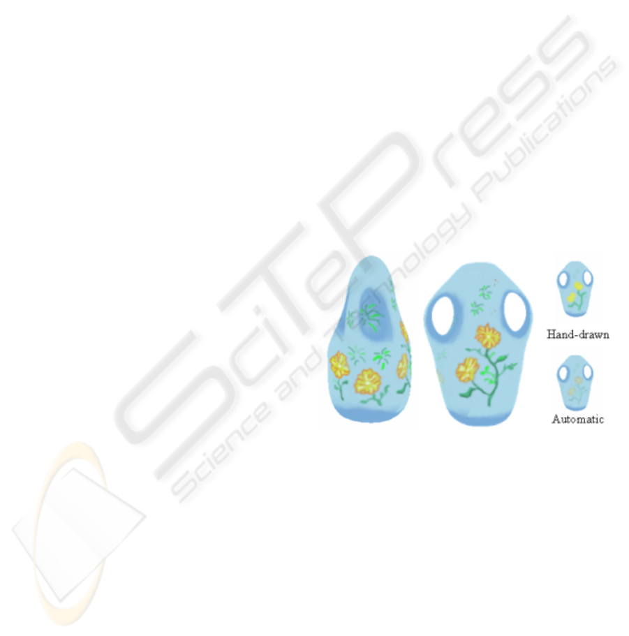
Figure 1: A vase with a flower pattern. The side pattern only
appears from the side. If the automatic down-sampling is
used, the pattern appears as shown on the bottom when the
object is at a distance. On the top, the hand-painted depth
effect is shown.
object should look like if it were fully lit. At this
point, we have enough information to render the ob-
ject, blending from the “dark” painting to the “light”
painting as the shading on the object changes.
The artist is then free to add more paintings. These
paintings may show what the object looks like at dif-
ferent shade values, what it should look like when
viewed from a particular angle, or from far away (see
Figures 1 and 2).
The system is designed to be user-intensive, under
the assumption that the user is a skilled artist and has
204
Grimm C. and Kowalski M. (2007).
PAINTING LIGHTING AND VIEWING EFFECTS.
In Proceedings of the Second International Conference on Computer Graphics Theory and Applications - GM/R, pages 204-211
DOI: 10.5220/0002072702040211
Copyright
c
SciTePress

a particular goal in mind. The effects that are created
using the system could be duplicated using combina-
tions of texture maps and shaders, and in fact, the ren-
dering system is amenable to a hardware implemen-
tation. The advantage of this approach is, we believe,
the directness of it.
We begin by putting this approach in context with
existing work (Section 2). We next discuss the system
as seen from the user’s point of view (Section 3). We
then discuss implementing the implementation details
(Section 4) including how to use the painting itself
as a texture map, even for non-manifold meshes. We
close with results and conclusions.
2 PREVIOUS WORK
This work continues the concept of using warm and
cool colors (Gooch et al., 1999) or painterly color
models (Sloan et al., 2001) or texture (Kulla et al.,
2003) to shade an object. We combine this with 3D
painting (Hanrahan and Haeberli, 1990; Teece, 1998;
Agrawala et al., 1995) to let the user paint both the
texture and the shade effects at the same time.
Several techniques exist for automatically shad-
ing models using common 2D techniques such as
hatching (Webb et al., 2002; Praun et al., 2001;
Jodoin et al., 2002), procedural pen-and-ink tex-
tures (Winkenbach and Salesin, 1994), and cartoon
shading (Johnston, 2002). There are two primary
challenges in stroke-based techniques. The first is
to maintain constant shading tones and stroke thick-
nesses as the model is viewed from different dis-
tances. This is achieved by creating a set of “artistic
mip-maps” (Klein et al., 2000). Each layer of the mip-
map contains all the strokes of the previous mip-map.
The second problem is maintaining consistent strokes
as the desired shading value changes; again, this is
achieved by adding strokes to existing strokes, creat-
ing increasingly darker tones. Together, these stroke
images form a 2D “spread sheet”, where moving in
one direction changes the perceived intensity, and the
other direction adjusts for the number of pixels the
model occupies. We adopt this “spread sheet” struc-
ture to store our paintings (see Figure 2).
In the non-photorealistic community there is a
growing body of stroke-based rendering systems that
are examining what it means to translate the concept
of “brush stroke” to a 3D model. Early work let
the user specify the model, the strokes, and how the
strokes should be applied to the rendering (Kowal-
ski et al., 1999). Harold (Cohen et al., 2000) was a
system that directly captured the user’s drawings and
placed them in a 3D world. Further work (Kalnins
et al., 2002) combined the automatic shading models
with an interactive system for specifying the sample
strokes and where they should go. We differ from this
approach in that the user specifies the tone and the
texture together.
Disney’s Deep Canvas (Daniels, 1999) was one of
the first systems to convert an artist’s 2D painting to
3D. Every stroke the artist made was “attached” to a
3D element in the scene. When the camera moved,
the strokes were re-oriented and scaled to match the
new viewpoint. When the viewpoint changed suffi-
ciently, the artist would paint the scene from this new
viewpoint. We adopt this notion of painting a series
of viewpoints, but interpolate and blend in the texture
map and not the strokes themselves.
3D painting requires a texture map, and a way to
“reach” every point on the object with the paintbrush.
A survey of the current approaches and problems can
be found in a technical report by Low (Low, 2001).
If a model has an existing texture map then we can
use that. Takeo (Igarashi and Cosgrove, 2001) intro-
duced a method for creating a texture map “on the
fly” by locally flattening out the mesh into the plane.
This works well for simple non-occluding meshes, but
becomes somewhat difficult for objects with handles.
Lapped textures (Praun et al., 2000) provide a method
for locally flattening out pieces of the mesh and tex-
ture mapping the pieces. One problem with using an
existing texture map is that the user’s paintings need
to be resampled into the texture map; Carr et. all (Carr
and Hart, 2004) provide an approach to automatically
adapt the texture map resolution in this case.
View-dependent texture maps first arose in the
context of image-based rendering (Debevec et al.,
1998). In this case, photographs are aligned with the
3D model automatically. As the camera viewpoint
changes, different sets of photographs are chosen and
combined. We use the weighting scheme outlined in
Buehler et. al. (Buehler et al., 2001) to combine our
paintings. This approach weights the blends based on
how close rays are in angular distance and resolution
(distance to the camera).
3 USER INTERFACE
In this section we describe the system from the user’s
point of view, leaving the details of the implementa-
tion for later sections.
When developing our system we chose to have
the user use an external program, such as Painter
tm
,
to create the images (or, alternatively, they can scan
hand-painted images in). This has the advantage that
the user can use their favorite method for creating the
PAINTING LIGHTING AND VIEWING EFFECTS
205
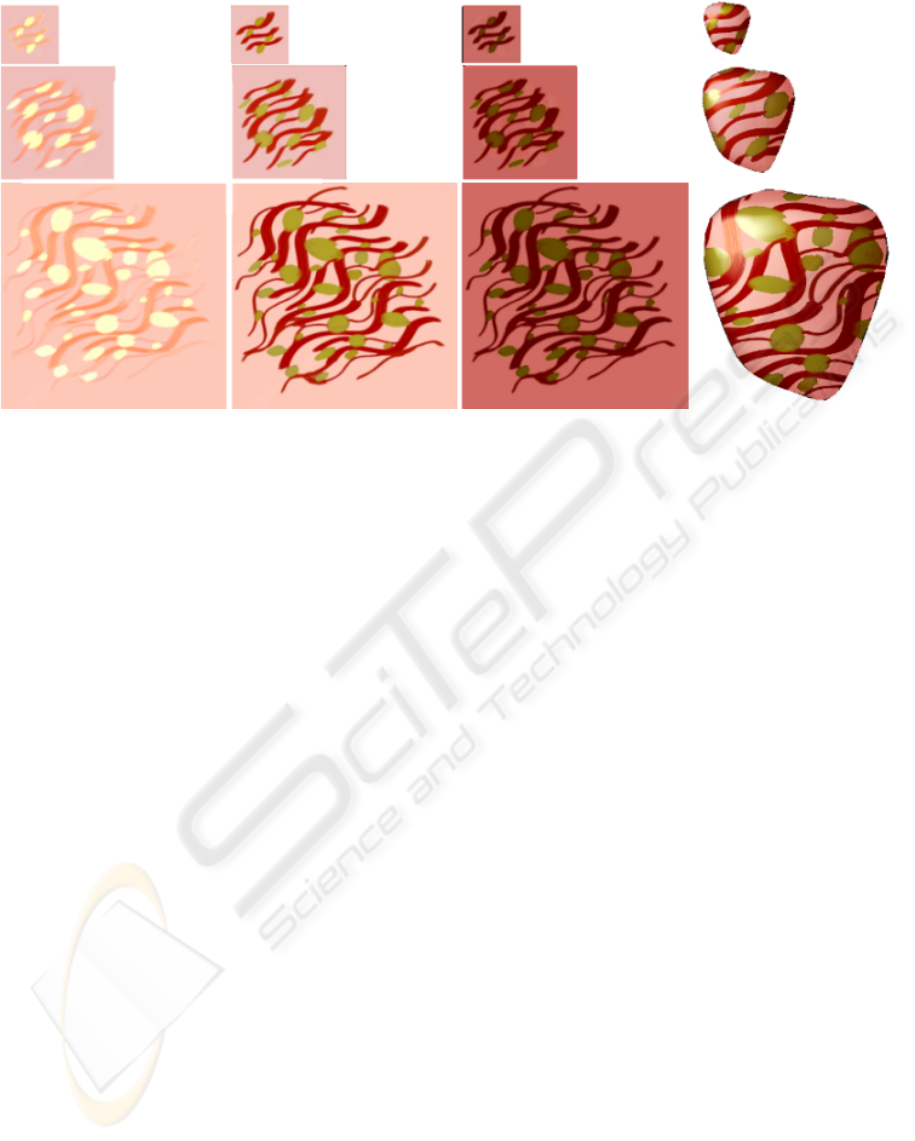
Figure 2: A lighting example using three shading values (1.0, 0.5, 0.0) and three mip-mapping levels. At far right is the object
rendered at three sizes with a spot-light behind the viewer’s left shoulder.
2D images, but it has the disadvantage of introduc-
ing an intermediate step between painting and view-
ing the results. We ameliorate this somewhat by pro-
viding tools for automatically making masks and mip-
maps, and creating an initial painting by rendering the
object using the existing images.
The system has two windows, a 3D one and a 2D
one. In the 3D window the user can change the cam-
era viewpoint and lights, see the results of one paint-
ing or a group of them, or what part of the object
is currently un-painted. In the 2D window the user
can page through the existing paintings, and add new
shade values or mip-map levels.
A “painting” consists of a set of mip-mapped
images (representing the shade values), and a sin-
gle, mip-mapped alpha-mask, all made from a single
viewpoint. Each painting also has two optional mip-
mapped images for controlling the lighting. The first
is a traditional bump-map image, the second is a mate-
rial “shinyness” parameter, which controls how sharp
the highlight is at that point.
To create a painting, the user first picks the camera
viewpoint using the 3D window. In the 2D window
they then name the painting and pick a shade value for
the first mip-mapped image. The automatically gener-
ated alpha-mask image is one where the object faces
the viewer, fading to black by the silhouette. The user
is free to edit this mask. The user can optionally ini-
tialize the mip-mapped image by rendering the object
at that shade value. At any time they can add a new
mip-mapped image for a different shade value.
We classify paintings into two categories; base-
coat and view-dependent. The base-coat paintings
cover the visible part of the object and serve as the
“base” texture. The view-dependent paintings only
appear for a limited range of view angles (see Fig-
ure 4). The user controls the view-angle ranges using
two sliders; the first controls the total visible angu-
lar distance, the second controls how fast the painting
fades out.
To help the user cover the object with paint-
ings and to seamlessly merge images across different
views, the user can render the object from the current
viewpoint using either the current shade value (shade
images) or in grey scale using the alpha-mask values.
Uncovered and background pixels are rendered in a
user-defined color.
A typical painting session begins with the user
picking some number of base-coat views, typically
4-6. For each base-coat view the user specifies two
shade values, one dark and one light, which creates
corresponding dark and light images. These images
initially contain a grey-scale rendering of the model.
The user paints the images, then reads them back in
and applies them to the model. The user then moves
to the next painting viewpoint and writes out images
that show the uncovered portion of the model as a grey
scale image, and the covered portion showing the dark
(or light) previous painting.
To deal with occlusions the system automatically
creates multiple layers for each view direction, let-
ting the user “strip off” layers as the go. For exam-
ple, layer zero for the vase was made first with six
paintings that covered the top, bottom, and four sides.
GRAPP 2007 - International Conference on Computer Graphics Theory and Applications
206
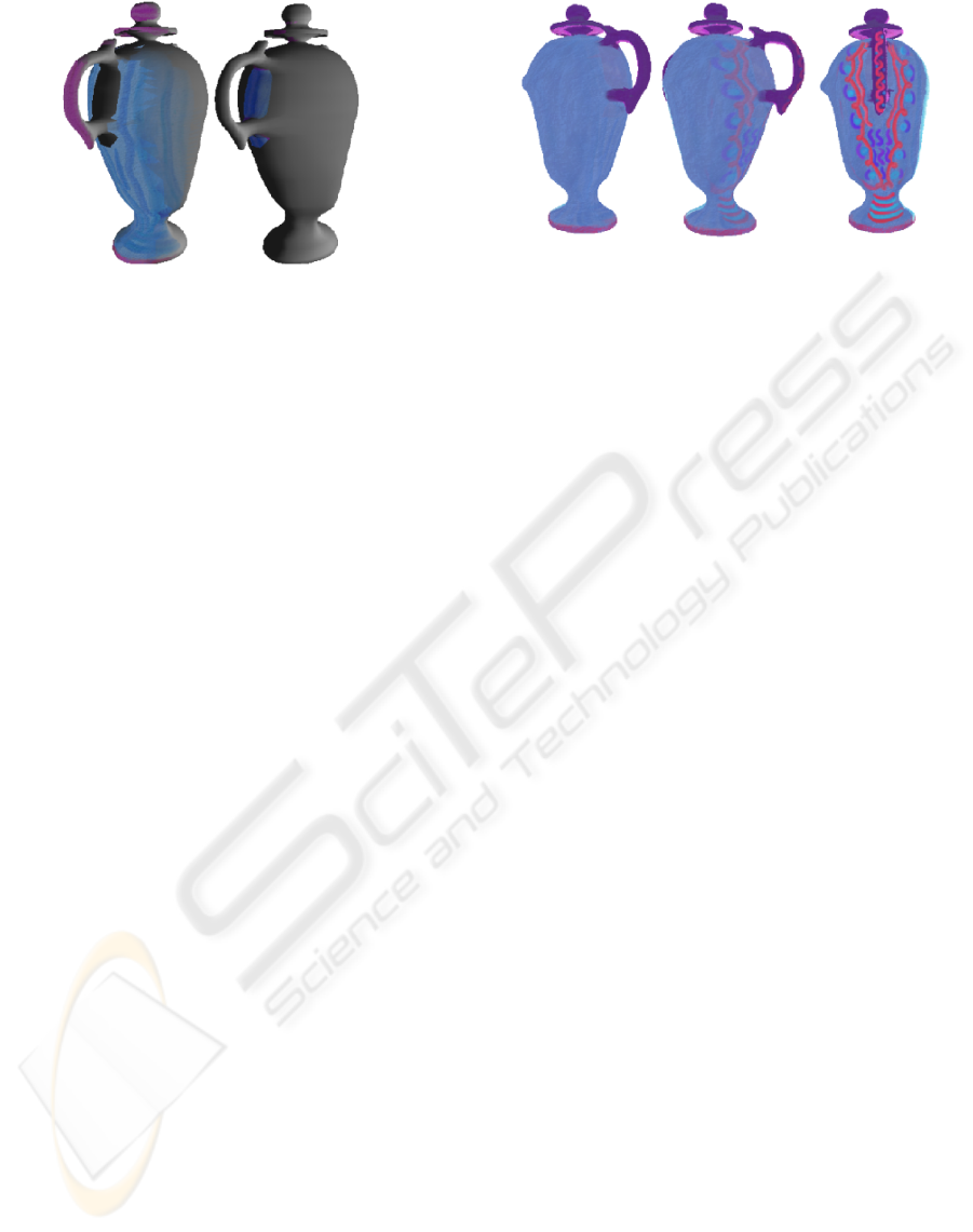
Figure 3: Splitting the object into two paintings to avoid
the self-occlusions. Left: The first layer contains the handle
and the body of the vase, except for the part under the han-
dle. Right: the part of the vase body that was covered by
the handle. The uncovered portion of the mesh is shown in
(smooth) grey.
This left uncovered gaps in the areas behind the han-
dles and around the lid. The user then picked six more
views, angled through the handle on each side and top
and bottom, to fill in the back side of the handles, the
vase body, and the remaining top and bottom of the
lid.
Once the initial base-coat is created the user has
several options:
• Produce mip-map levels of the current paintings
and edit them to create effects based on viewing
distance and screen size.
• Add more shade levels to control the dark-to-light
transitions.
• Add one or more view-dependent paintings (each
of which contains one or more shade levels).
• Add a bump map. This is also equivalent to the
traditional bump map and is used in the lighting
calculation to adjust the surface normals of the
texture map.
• Add a shinyness image. This is equivalent to the
traditional shinyness parameter and controls how
sharp the highlights are.
If the object is self-occluding then the user has the
option of separating the object into pieces and paint-
ing each of the pieces with two or more paintings (see
Figure 3). This is discussed in more detail in the tex-
ture section.
4 IMPLEMENTATION
The rendering process (Section 4.1) describes how to
combine the paintings into a single, shaded texture
Figure 4: Left: The vase with just the base-coat. Middle:
The angle at which the side view-dependent painting begins
to appear. Right: The side view-dependent painting fully
visible.
map. Section 4.2 describes how to map a painting’s
pixels to the faces of the mesh model, in particular,
how to cope with self-occluding models. If the object
already has a texture map atlas then we can use it in
one of two ways.
• Create a texture map atlas for each unique shade
value of the base coat, each view-dependent paint-
ing, and optionally, the bump and shinyness im-
ages. Pre-process each shade value of each paint-
ing into its corresponding texture map atlas, us-
ing the individual painting’s mask values to blend
the images and setting un-covered pixels to zero.
Compute the final texture map image as described
in the rendering section by blending the texture
map atlases.
• Render into the texture map atlas and then display
the object.
4.1 Rendering
This section defines how the base-coat paintings are
lit, blended, and then combined with any view-
dependent paintings. The view-dependent paintings
are blended in using image-based rendering tech-
niques similar on the ones in Buehler et. al. (Buehler
et al., 2001). The lighting happens on a per-painting
basis, while the blending happens at the fragment
level.
4.1.1 Lighting the Paintings
We calculate a single, shaded, mip-mapped image
for each painting by finding the intensity value at
each pixel and interpolating between the images that
bracket that intensity value. If there are no bracketing
values then we take the closest shade level.
Suppose we have N images t
i
at shade values
0 ≤ d
i
≤ 1, with d
i
< d
i+1
. For each pixel in the
PAINTING LIGHTING AND VIEWING EFFECTS
207

painting we have a point p and a normal n (see Sec-
tion 4.2). We first calculate the shade value s at the
pixel using the standard lighting calculation (Foley
et al., 1997) (l is the look vector, I
a
,I
d
,I
s
the ambient,
diffuse, and specular light values, d the distance to the
light source, l the vector to the light source, and e is
either the default or read from the shinyness image):
s = I
a
+
1
c
0
+ c
1
d + c
2
d
2
∑
(I
d
n · l + I
s
(r · l)
e
)
Next, we use that shade value to determine the two
bracketing texture maps and how much of each to
take:
i s.t. d
i
≤ s ≤ d
i+1
(1)
t
s
(x,y) =
d
i+1
− s
d
i+1
− d
i
t
i
+
s − d
i
d
i+1
− d
i
t
i+1
(2)
We can either blend each of the color channels inde-
pendently, or average the RGB values in s and use the
same blend value for all channels. This calculation is
performed for each mip-map level.
If there is a bump map image then we alter the nor-
mal before calculating the shade value (Foley et al.,
1997). Note that we can pre-compute the point and
the perturbed normal and save them as mip-mapped
images in the painting. We can then perform a pre-
rendering pass with the fragment shader to compute
the shaded image.
4.1.2 Combining Paintings
We use the alpha mask in each painting to determine
the contribution of each lit base-coat painting. We
sum up the contributions of each painting at each pixel
in the final image and normalize.
The view-dependent paintings over-ride the base-
coat paintings. We first calculate the percentage of
each additional painting we wish to include. This
percentage is derived from the view-painting’s alpha-
mask, the current view direction, and the user-
specified maximum angle and fall-off. We then nor-
malize the additional contributions, using the com-
bined base-coat if the sum of the contributions is less
than one.
The view-dependent fade value w
v
is calculated
as follows. Each VD map has an associated viewing
direction, represented by an eye point p
e
and an at
point p
a
. The at point lies along the look vector and
in a plane containing the model. Given a new eye
point p
0
e
we can calculate w
v
as follows:
d =
p
e
− p
a
||p
e
− p
a
||
·
p
0
e
− p
a
||p
0
e
− p
a
||
(3)
w
v
=
0 d ≤ d
m
((d − d
m
)/(1 − d
m
))
f
d > 0
(4)
where 0 < d
m
< 1 is the cut-off angle specified by
the user and 1 < f < ∞ is the speed of the fall-off,
also specified by the user. This is essentially a camera
angle penalty (Buehler et al., 2001). w
v
is multiplied
by the alpha-mask to get the final percentage. This
equation ignores the viewing distance (the appropriate
mip-map level will be selected by OpenGL) and does
not take into account where the object is in the field
of view.
4.1.3 Image-space Size
We use OpenGL’s mip-mapping routines to account
for changes in resolution. The user may over-ride the
default mip-maps, if desired (see Figure 2).
To reduce the computation time of the filtered im-
ages we can save and propagate down the shade val-
ues that were calculated at the top level.
4.2 Texture Maps from Paintings
To create a texture map from a painting we project the
vertices of the faces onto the image and use the pro-
jected locations as texture coordinates. Our algorithm
addresses the two major problems with this approach,
occlusion and shared faces.
For any reasonably complicated model there will
be portions of the model that are occluded. This leads
to two problems. First, if two faces map to the same
pixel then they both get colored with that pixel’s color.
This is desirable for two neighboring faces but not so
for two overlapping faces. Second, it may be difficult
to find a view where the occluded faces are visible.
We approach the problem of occlusion by break-
ing the model’s mesh into layers (see Figure 3). As a
layer of the mesh is painted (with one or more paint-
ings) we “peel off” that layer to expose the next set of
faces to be painted. We also ensure that the occluded
faces (even partially occluded ones) are not used in a
painting. To make painting simpler, and to avoid tex-
ture blending artifacts, we enforce a pixel wide halo
around faces that occlude other ones.
4.3 Data Structures
For each painting we store the layer, the list of faces
associated with that painting, texture map coordinates
for the vertices, the camera, and an alpha mask. We
GRAPP 2007 - International Conference on Computer Graphics Theory and Applications
208

automatically generate all layers and let the user pick
which one(s) they wish to edit.
4.4 Algorithms
4.4.1 Faces for a Painting
We run a modified two-pass scan-line algorithm to de-
termine which faces are visible, which are occluded,
and to calculate the point and normal for each pixel.
In the first pass we perform the standard scan-line al-
gorithm to calculate the points and normals, using an
id buffer to keep track of the faces that map to each
pixel. Any face which falls across the edge of the im-
age or is back-facing is eliminated at this stage.
In the second pass we increase the size of the poly-
gon by half a pixel in all directions and keep track of
all of the faces that map into each pixel, sorted by
depth. For each pixel covered by more than two faces
we look for possible occlusions. A face f is occluded
if there is a face g that is closer and g is not a neighbor
of f in the mesh.
To determine if f and g are neighbors we look for
a path of adjacent faces { f
a
} that connect f to g such
that every face in { f
a
} is forward-facing and maps to
the current pixel. Usually f and g will either be adja-
cent or widely separated, but it is possible for several
small faces to map to a single pixel.
If the mesh has intersecting polygons then the
above algorithm will end up throwing both polygons
out. As an alternative, we can sort the faces by their
depth order (essentially the Painter’s (Foley et al.,
1997) algorithm) and perform occlusion testing on
this ordered list. In this case, any face that overlaps
and is not a neighbor is thrown out.
To create subsequent layers we repeat, leaving out
any faces belonging to the previous layers.
4.4.2 Automatic Alpha-masks
Faces will usually be covered by one or more paint-
ings and we want to blend smoothly from one paint-
ing to the next. This is essentially an image-based
rendering problem; we want to take the paintings that
best cover a face and combine them based on the cam-
era angle relative to that face. We use the angle, α
i
,
between the pixel normal and the ray from camera i
through that pixel to calculate the mask value. Let α
m
be the maximum angle we wish to allow (slightly less
than 90
deg
). We use a maximum angle rather than the
largest angle because we may only have two paint-
ings. The alpha-mask value is then 1 − α
i
/α
m
.
5 RESULTS
In Figure 5 we see the same scene with different por-
tions painted by two different artists. Most of the ob-
jects have between 6 and 8 paintings. The vase and
the table both required slightly more paintings be-
cause of occlusion effects. The vase also has view-
dependent effects, as can be seen in the accompanying
video. The orange and table both have bump maps.
In Figure 7 we see two different plants, each with
approximately 20,000 faces. The table, pot, and plant
each have 6-8 paintings. For the plant we did not do
any occlusion culling; all of the faces map to one of
the paintings.
Figure 6 shows a model with a single shade value
and multiple view-dependent textures.
Rendering time for the scenes was between 1 and
5 seconds on a 2GHz Pentium processor.
6 CONCLUSIONS
We have presented a system for painting lighting and
viewing effects that is a simple extension to existing
texturing and lighting techniques. The approach is
suitable for hardware acceleration. We also provide a
method for building texture maps directly from user’s
paintings.
The system has been used by an artist with no
computer science background. The artist is learning
to use 3DS Max in addition to using in-house soft-
ware. Unfortunately the artist has no experience with
traditional 3D painting systems, so he cannot make
any comparisons in that area. He does have this to
say about the painting system versus the materials and
shading system of 3DS Max:
I am designing both the dark and light textures
and the computer is putting them together for
me. In 3DS Max I don’t have that same di-
rect control - I may be able to import a tex-
ture, but often end up spending hours tweak-
ing lighting and material properties to find the
dark and light images I’m looking for. This is
a much simpler system to learn for someone
coming from traditional media - 3DS Max is
very powerful, and offers so many tools, but
it doesn’t let traditionally trained people take
advantage of their learned skills.
We believe that “painting” provides a viable alter-
native to specifying lighting and viewing effects us-
ing traditional materials and shaders, especially for
artists who are transitioning from traditional media to
3D computer graphics.
PAINTING LIGHTING AND VIEWING EFFECTS
209
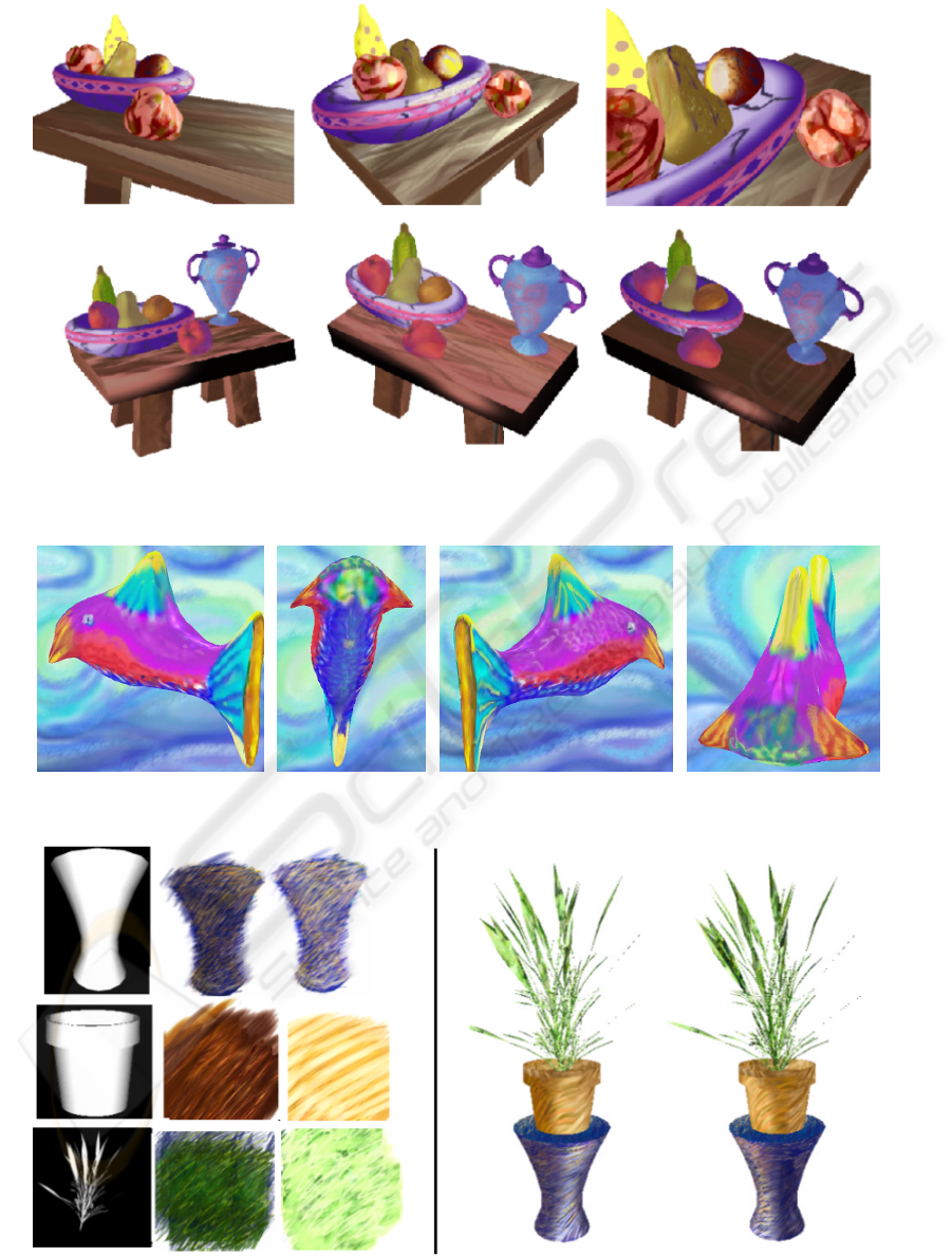
Figure 5: The entire still life. Each object was painted individually with between 8 and 12 paintings. Top row: Intensity
values. Bottom row: Rendered images.
Figure 6: Fish with view-dependent scales and one shade-value base-coat.
Figure 7: Painting plants. Shown are example “dark” and “light” paintings for the table, pot, and plant. The images on the far
left are the alpha masks for those paintings. On the right is two frames from an animation.
GRAPP 2007 - International Conference on Computer Graphics Theory and Applications
210

ACKNOWLEDGEMENTS
This research was funded in part by NSF grant CCF-
0238062.
REFERENCES
Agrawala, M., Beers, A. C., and Levoy, M. (1995). 3d paint-
ing on scanned surfaces. In SI3D ’95: Proceedings
of the 1995 symposium on Interactive 3D graphics,
pages 145–ff., New York, NY, USA.
Buehler, C., Bosse, M., McMillan, L., Gortler, S. J., and Co-
hen, M. F. (2001). Unstructured lumigraph rendering.
In SIGGRAPH 2001, pages 425–432.
Carr, N. A. and Hart, J. C. (2004). Painting detail. ACM
Trans. Graph., 23(3):845–852.
Cohen, J., Hughes, J., and Zeleznik, R. (2000). Harold: A
world made of drawings.
Daniels, E. (1999). Deep canvas in disney’s tarzan. In
ACM SIGGRAPH 99 Conference abstracts and appli-
cations, page 200.
Debevec, P. E., Yu, Y., and Borshukov, G. D. (1998). Ef-
ficient view-dependent image-based rendering with
projective texture-mapping. In Eurographics Render-
ing Workshop 1998, pages 105–116.
Foley, J., van Dam, A., Feiner, S., and Hughes, J. (1997).
Computer Graphics: Principles and Practice. Addi-
son and Wesley.
Gooch, B., Sloan, P.-P. J., Gooch, A., Shirley, P. S., and
Riesenfeld, R. (1999). Interactive technical illustra-
tion. 1999 ACM Symposium on Interactive 3D Graph-
ics, pages 31–38.
Hanrahan, P. and Haeberli, P. (1990). Direct wysiwyg pait-
ing and texturing on 3d shapes. In Siggraph ’90, vol-
ume 24, pages 215—223.
Igarashi, T. and Cosgrove, D. (2001). Adaptive unwrapping
for interactive texture painting. In 2001 ACM Sympo-
sium on Interactive 3D Graphics, pages 209–216.
Jodoin, P.-M., Epstein, E., Granger-Pich
´
e, M., and Ostro-
moukhov, V. (2002). Hatching by example: a statis-
tical approach. In NPAR 2002: Second International
Symposium on Non Photorealistic Rendering, pages
29–36.
Johnston, S. F. (2002). Lumo: Illumination for cel anima-
tion. In NPAR 2002, pages 45–52.
Kalnins, R. D., Markosian, L., Meier, B. J., Kowalski,
M. A., Lee, J. C., Davidson, P. L., Webb, M., Hughes,
J. F., and Finkelstein, A. (2002). Wysiwyg npr: Draw-
ing strokes directly on 3d models. ACM Transactions
on Graphics, 21(3):755–762.
Klein, A. W., Li, W. W., Kazhdan, M. M., Correa, W. T.,
Finkelstein, A., and Funkhouser, T. A. (2000). Non-
photorealistic virtual environments. In Proceedings of
ACM SIGGRAPH 2000, pages 527–534.
Kowalski, M. A., Markosian, L., Northrup, J. D., Bourdev,
L., Barzel, R., Holden, L. S., and Hughes, J. F. (1999).
Art-based rendering of fur, grass, and trees. In Pro-
ceedings of SIGGRAPH 99, pages 433–438.
Kulla, C., Tucek, J., Bailey, R., and Grimm, C. (2003).
Using texture synthesis for non-photorealistic shading
from paint samples. In Pacific Graphics, pages 477–
481.
Low, K.-L. (2001). Simulated 3D painting. Technical Re-
port TR01-022.
Praun, E., Finkelstein, A., and Hoppe, H. (2000). Lapped
textures. In Proceedings of ACM SIGGRAPH 2000,
pages 465–470.
Praun, E., Hoppe, H., Webb, M., and Finkelstein, A. (2001).
Real-time hatching. In Proceedings of ACM SIG-
GRAPH 2001, pages 579–584.
Sloan, P.-P., Martin, W., Gooch, A., and Gooch, B. (2001).
The lit sphere: A model for capturing NPR shading
from art. In Watson, B. and Buchanan, J. W., editors,
Proceedings of Graphics Interface 2001, pages 143–
150.
Teece, D. (1998). 3d painting for non-photorealistic ren-
dering. In ACM SIGGRAPH 98 Conference abstracts
and applications, page 248.
Webb, M., Praun, E., Finkelstein, A., and Hoppe, H. (2002).
Fine tone control in hardware hatching. In NPAR
2002: Second International Symposium on Non Pho-
torealistic Rendering, pages 53–58.
Winkenbach, G. and Salesin, D. H. (1994). Computer-
generated pen-and-ink illustration. In Proceedings of
SIGGRAPH 94, pages 91–100.
PAINTING LIGHTING AND VIEWING EFFECTS
211
