
A Vision-based Path Planner/Follower
for an Assistive Robotics Project
⋆
Andrea Cherubini
1
, Giuseppe Oriolo
1
, Francesco Macr`ı
1
,
Fabio Aloise
2
, Febo Cincotti
2
and Donatella Mattia
2
1
Dipartimento di Informatica e Sistemistica
Universit`a di Roma “La Sapienza”
Via Eudossiana 18, 00184 Roma, Italy
2
Fondazione Santa Lucia IRCCS
Via Ardeatina 306, 00179 Roma, Italy
Abstract. Assistive technology is an emerging area where robots can be used
to help individuals with motor disabilities achieve independence in daily living
activities. Mobile robots should be able to autonomously and safely move in the
environment (e.g. the user apartment), by accurately solving the self-localization
problem and planning efficient paths to the target destination specified by the user.
This paper presents a vision-based navigation scheme designed for Sony AIBO,
in ASPICE, an assistive robotics project. The navigation scheme is map-based:
visual landmarks (white lines and coded squares) are placed in the environment,
and the robot utilizes visual data to follow the paths composed by these land-
marks, and travel to the required destinations. Performance of this vision-based
scheme is shown by experiments and comparison with two previously existing
ASPICE navigation modes. Finally, the system is clinically validated, in order to
obtain a definitive assessment through patient feedback.
1 Introduction
The development of service robots for healthcare and assistance to elderly or disabled
persons is an active area of research. A typical use of robots in this context is directed
to partial recovery of the patient mobility. Semi-autonomous navigation systems for
wheelchairs are an example. In these applications, mobile robots must acquire a high
degree of autonomous operation, which calls for accurate and efficient position deter-
mination and verification for safe navigation in the environment. In many recent works,
this has been done by processing information from the robot vision sensors [1].
Implicitly or explicitly, it is imperative for a vision system meant for navigation
to incorporate within it some knowledge of the environment. In particular, map-based
⋆
This work has been partially supported by the Italian Telethon Grant GUP03562. This
manuscript describes variations of a work submitted at the IEEE International Conference
on Robotics and Automation 2007: the main contribution concerns the ASPICE vision-based
navigation mode – vision related topics have been extended in this version.
Cherubini A., Oriolo G., Macrì F., Aloise F., Cincotti F. and Mattia D. (2007).
A Vision-based Path Planner/Follower for an Assistive Robotics Project.
In Robot Vision, pages 77-86
DOI: 10.5220/0002068700770086
Copyright
c
SciTePress

robot navigation systems can be based on user-created geometric models within the en-
vironment [2]. The vision system will search and identify some known landmarks and
use them, along with a provided map, to estimate the robot position (self-localization)
by matching the observation (image) against the expectation (landmark descriptions).
Visual navigation that uses patterns based on an identification code, has been exploited
in [3]. More recent works include a guidance system for the visually impaired, based
on visual cues on the ceiling [4], and a localisation system for autonomous wheelchairs
based on light-emitting markers on the floor [5].
In this paper, we present a vision-based path planner/follower designed for an in-
door structured environment. The system enables the robot to travel to a target destina-
tion, by extracting, visually tracking, and following, known artificial paths. This robot
navigation system has been utilized within the ASPICE (Assistive System for Patient’s
Increase of Communication, ambient control and mobility in absence of muscular Ef-
fort) project [6]. The ASPICE system enables a disabled user to remotely control home-
installed appliances, including the Sony AIBO, a commercial mobile robot.
The paper is organized as follows. In Sect. 2, the main features of the AIBO robot
are described. Section 3 presents the vision primitives developed for the robot frame-
work. The vision-based navigation scheme that we designed and implemented, is out-
lined in Section 4. Experiments are reported in Section 5. Other issues not covered in
the previous sections are mentioned in the conclusion.
2 The Robot Platform: AIBO
The platform used in this work is a quadruped robot, Sony AIBO ERS-7, pictured in
Fig. 1. The robot is equippedwith 20 actuated joints, a CMOS camera, two distance sen-
sors (on the head and on the chest), and other equipment not used in this work. A wire-
less card enables remote control. AIBO’s real-time operating system APERIOS runs a
specialized layer called OPEN-R, a cross-development environment based on C++. The
robot behavior is programmed by loading executable and configuration files on a mem-
ory stick which is read by the on-board processor. From a kinematic viewpoint, AIBO
can be considered as an omnidirectional robot, i.e., three velocities (forward v
x
, lateral
v
y
, and angular v
θ
around the robot center) can be independently specified (Fig. 2). In
spite of these features, AIBO presents many limitations. The most severe are:
– the closed hardware prevents the addition of sensors and/or actuators;
– since Sony does not release the code of its driver, we had to realize from scratch an
ad hoc driver for this work;
– vibrational and slipping effects during the quadruped gait cycle make odometric
reconstruction very inaccurate in the long run;
– the variable attitude of AIBO during its gait precludes the use of an external sensory
system (e.g., based on infrared triangulation with a detector placed on the robot) for
solving the localization problem.
78
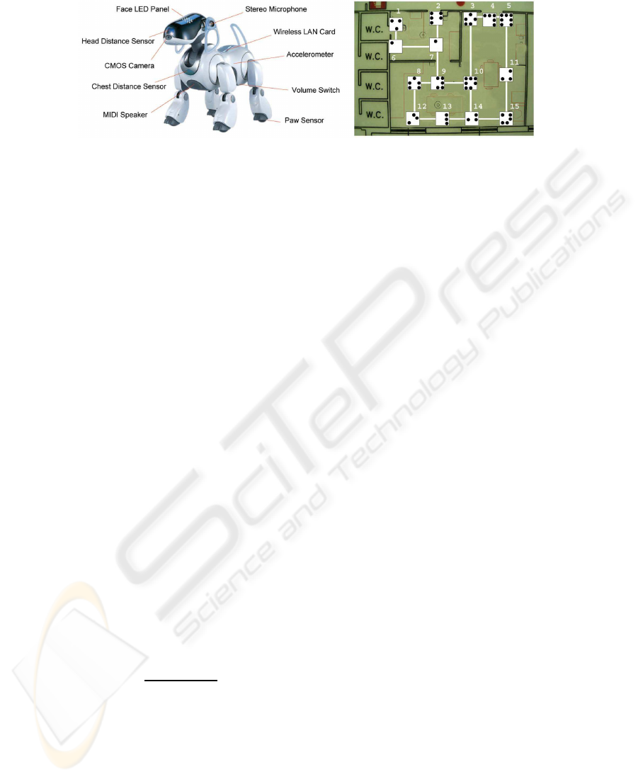
Fig.1. ASPICE features: the robot Sony AIBO ERS-7(left), and the roadmap used for vision-
based navigation, with the ID labels of each coded square (right).
3 Vision Primitives
In order to extract and track the artificial visual landmarks (VL) on the navigation path,
specific vision primitives have been developed and integrated in the driver framework.
Let us define the three reference frames which will be used (shown in Fig. 2):
– the robot frame with origin fixed at the robot center projection on the ground, x
axis in the forward direction, y axis pointing left, and z axis vertical;
– the camera frame with origin fixed in the camera center, horizontal
c
x axis pointing
right,
c
y axis pointing downward, and
c
z axis pointing forward;
– the image frame with origin fixed at the top left corner of the image, horizontal
i
x
axis pointing right, and
i
y axis pointing downward.
The VLs that we use are straight white lines (SWL) and coded squares (CS) placed
on the floor. Thus, a straight white line extractor (SWLE) and a coded square extractor
(CSE) have been developed. Moreover, the VLs should be located in sequential scenes.
This is accomplished by a visual landmark tracker (VLT).
3.1 Straight White Line Extractor
A requirement of the robot driveris straight white line extraction. In order to be indepen-
dent from color classification, the SWLs are detected by search only on the luminance
signal I
i
x,
i
y
. Thus, line edges are searched at pixels with a strong variation of lu-
minance with respect to that of adjacent pixels. For each pixel located in p = [
i
x
i
y]
T
the gradient of luminance ∇I(p) is computed, using the Roberts operator [7] as in [8]:
s(p) = I
`
i
x + 1 ,
i
y + 1
´
− I
`
i
x ,
i
y
´
t(p) = I
`
i
x + 1 ,
i
y
´
− I
`
i
x ,
i
y + 1
´
|∇I(p)| =
p
s(p)
2
+ t(p)
2
∠∇I(p) = ATAN2(s(p), t(p))
(1)
where |∇I(p)| is the magnitude and ∠∇I(p) ∈ (−π, π] is the direction of the pixel lu-
minance gradient (with respect to line
i
y = −
i
x and positive CW, see Fig. 2). Edges are
then detected by applying a threshold test to |∇I(p)|. We use a threshold dependent on
the mean value of |∇I(p)| on the given image to derive the set of image edge pixels P
e
79
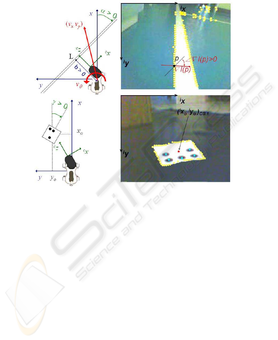
Fig.2. Relevant variables utilized in: extraction and tracking of straight white lines (above), and
extraction and tracking of coded squares (below).
(marked in yellow in Fig. 2). Adaptive thresholding makes the edge detection algorithm
more robust to varying light conditions, as compared to similar works implemented in
environments where light conditions had to be controlled. Afterwards, by comparing
(with another threshold test) the luminance gradient directions of “near” edge pixels,
pixels belonging to straight lines are identified and grouped in subsets. Indicating with
N
SW L
the total number of straight white lines extracted on an image, the line pixel
subsets are noted: P
SW L,j
(j = 1...N
SW L
). Each P
SW L,j
defines a line detected on
the image, and must contain at least n
SW L,min
pixels.
We tested other edge detection algorithms (Sobel, Susan), but the Roberts operator
showed better results, although the aforementioned algorithms are more efficient for
color space based extraction [9]. Besides, due to its low computation time, this line
extraction method was preferred to the Hough Transform technique, which we also
experimented. In conclusion, the SWLE algorithm returns the coordinates of the pixels
belonging to the N
SW L
lines extracted on the image frame (Fig. 2):
[
i
x
r
i
y
r
]
T
SW L,j
∈ P
SW L,j
r = 1, . . . , n
j
j = 1, . . . , N
SW L
(2)
80

3.2 Coded Square Extractor
Along with the SWLs, we have used as visual landmarks a set of white coded squares
laid on the ground. The identity and orientation of each square is uniquely identified
through a black dots code, as in [2]. The choice of binary coding, i.e., black and white,
is aimed at using luminance variation, instead of color classification, for extracting the
CS characteristics. We arranged from 1 to 7 black dots on the squares border, in order
to generate configurations which uniquely define the landmark identity (defined by its
label: ID) and orientation. The 15 landmarks which we used can be seen in Fig. 1.
In practice, edges of squares are searched within the set of edge pixels P
e
derived
as in the SWLE. The robot frame coordinates of all edge pixels are derived from their
image frame coordinates, with the projection which will be presented below. Then, the
projected edges are fitted with a square mask with the same dimensions as the CS,
in order to detect the pixels belonging to the square perimeter. These define a subset
of P
e
for each square (see Fig. 2). Indicating with N
CS
the total number of coded
squares extracted on the image, the subsets of perimeter pixels of each square l are
noted: P
CS,l
(l = 1...N
CS
). Each P
CS,l
defines a coded square detected on the image,
and must contain at least n
CS,min
pixels. Afterwards, the image is scanned along the
segments (scanlines) leading from the center to the perimeter of the CS, and pixels on
such segments are classified by using a binary segmentation which uses the mean value
of I on the image as threshold. Corke [10] showed how binary segmentation is affected
by noise, threshold selection and edge gradient. However, in this application, the choice
of binary coding and the use of binary segmentation only in a small image window, and
with adaptive thresholding, reduces these problems. Finally, black dots are extracted by
associating a sufficient number of near black pixels found on the scanlines.
In conclusion, the CSE returns, for each of the N
CS
detected coded squares: the
image coordinates of the square center o and of the centers of the n
dots
black dots
(respectively marked in red, and in cyan in Fig. 2):
[
i
x
o
i
y
o
]
T
CS,l
[
i
x
m
i
y
m
]
T
CS,l
l = 1, . . . , N
CS
m = 1, . . . , n
dots
n
dots
= 1, . . . , 7
(3)
3.3 Visual Landmark Tracker
The SWLE and CSE only take into account information from the current image, and
give no long-term knowledge. Thus, consistent landmarks must be obtained by com-
paring the extracted landmarks over consecutive images. This is done by projecting
the characteristic points of each extracted visual landmark VL from the image frame
[
i
x
i
y]
T
V L
to the robot frame [x y z]
T
V L
. Such mapping is not one-to-one, and can only
determine the projecting ray of the point. However, in our application, since all the VLs
are on the ground plane, the problem can be solved in closed form.
In fact, given the intrinsic parameters of the camera, the projecting ray in camera
frame coordinates corresponding to each [
i
x
i
y]
T
V L
can be derived [10]. Besides, the
homogeneous transformation matrix representing the camera frame pose with respect to
the robot frame can be computed through the robot joint positions by using the Denavit
and Hartenberg method as in [8]. This matrix can be used, along with the projecting ray
81

expression in camera frame coordinates, and with the ground plane geometric constraint
z
V L
= 0, to derive [x y 0]
T
V L
in the robot frame.
The robot frame coordinates of SWL points [x
r
y
r
0]
T
SW L,j
are then processed with
a least square error algorithm to identify the parameters [b α]
T
SW L,j
of each line: b is the
signed distance between the nearest line point L and the robot (positivefor y
L
> 0), and
α ∈
−
π
2
,
π
2
denotes the orientation offset. The CS characteristic points [x
o
y
o
0]
T
CS,l
and [x
m
y
m
0]
T
CS,l
are processed to obtain the identity ID
l
= 1...15 and orientation γ
l
of each square. VLs extracted and projected at previous frames are displaced according
to the robot measured motion and compared with the current landmarks for checking
consistency and filtering out false positives. The algorithm returns the characteristics of
the VLs, validated in a sufficient number of consecutive frames (Fig. 2):
[b α]
T
SW L,j
j = 1, . . . , N
SW L
ID
l
γ
l
[x
o
y
o
0]
T
CS,l
l = 1, . . . , N
CS
(4)
4 The Vision-based Navigation Scheme
The vision-based navigation (VBN) scheme that we developed relies on a physical
roadmap (Fig. 1) connecting all relevant destinations in the experimental arena, and on
a visual servoing scheme. In practice, the robot plans and follows the path to destination
according to visual data. Since the VLT returns the position of the visual landmarks rel-
ative to the robot, position-based visual servo control turns out to offer a better solution
than image-based servoing [10]. The roadmap is formed by streets and crossings, all
realized in white adesive tape and laid on the ground. The vision primitives are used to
identify streets (i.e., straight white lines) and crossings (i.e., coded squares). The robot
autonomous behavior is represented by a Petri Nets based framework which has been
successfully deployed on the AIBO Platform in the Robocup field [11]. The VBN Plan
uses the following actions: Seek nearest landmark, Approach nearest landmark, Follow
street, Plan path to destination. Note that at all times during the actions, the vision prim-
itives are also executed for searching and updating perceived data, and the robot keeps
the nearest seen landmark centered in the image plane, by solving the inverse kinemat-
ics problem for the head joints. The VBN Plan repeats the actions until the destination
is reached. Transitions that start or terminate the actions represent events (e.g., Street
seen, or Crossing near) which are triggered by conditions on sensed information (e.g.,
distance from a line). In the rest of this section, the four actions are briefly described.
Seek nearest landmark AIBO seeks VLs by exploring the environment, while avoiding
collisions. The robot alternates predefined forward and rotation steps.
Approach nearest landmark When it perceives a landmark (preferably a crossing) with
the SWLE or CSE, and tracks it with the VLT, the robot approaches it, in order to
get a better perception, which can be useful for localization purposes. It is a posture
stabilization task with reference configuration defined by the position and orientation
of the landmark. The walk that drives the robot implements a proportional closed-loop
82

control strategy for reducing the robot relative distance and orientation with respect to
the landmark. This is done by setting:
v
x
= κ
T
x
V L
v
y
= κ
T
y
V L
v
θ
= −κ
R
θ
V L
(5)
In the case of SWL approaching, [x y θ]
T
V L
= [b sin α b cos α − α]
T
. Similarly, for CS,
[x y θ]
T
V L
= [x
o
y
o
− γ]
T
. In both cases, κ
T
and κ
R
are positive given gains.
Follow street When the robot is sufficiently near to a street but has not yet detected a
crossing, it should solve the path following problem for the SWLs, until at least one
crossing is detected. The task can be achieved by using only control variable v
θ
and
setting constant v
x
= v
f
> 0 and null v
y
= 0. Linear feedback control can be realized
by tangent linearization of
˙
b and ˙α, in the neighborhood of (b = 0, α = 0). This gives
a second order linear system which is controllable, and thus asymptotically stabilizable
by linear feedback on v
ϑ
with an appropriate choice of positive gains k
2
and k
3
:
v
ϑ
= (k
2
b − k
3
α) v
f
(6)
Plan path to destination When a crossing is detected with the CSE, and tracked with
the VLT, the robot has univocally identified its ID and orientation. This information,
along with the CS position in the robot frame, and with the map, identifies the robot
pose (position and orientation). The robot then utilizes a Dijkstra-based graph search to
find the shortest path to the destination. Depending on the result of the graph search,
the robot will approach and follow another street (repeat the corresponding actions in
the plan), or stop if the crossing corresponds to the desired destination.
5 Experiments
In this section, we will outline the main characteristics of the ASPICE system, and show
the results of two experiments: the first is a comparison between VBN and the two exist-
ing ASPICE navigation modes, while the second achieves autonomous battery charging
(clips are available at: http://www.dis.uniroma1.it/∼labrob/research/ASPICE.html).
The ASPICE system enables users to drive several output devices (the domotic ap-
pliances or AIBO). The video feedback from the robot camera to the user is fundamental
for increasing his/her sense of presence within the environment. Several input devices
(including a Brain Computer Interface) can be used to select commands, for driving
AIBO, through a Graphic User Interface (GUI). Since an objective of the project is
compatibility with a variety of users and their level of disability, three navigation modes
have been developed for AIBO: Single step, Semi-autonomous and Autonomous mode.
Each navigation mode is associated to a ASPICE GUI (see Fig. 3). In single step mode,
the robot can be driven, with a fixed step size, in any six directions (forward, back-
ward, lateral left/right, CW and CCW rotations). Before performing the command, the
robot verifies with the distance sensors if the step can be performed without colliding.
In semi-autonomous mode, the user specifies the main direction of motion: the robot
83
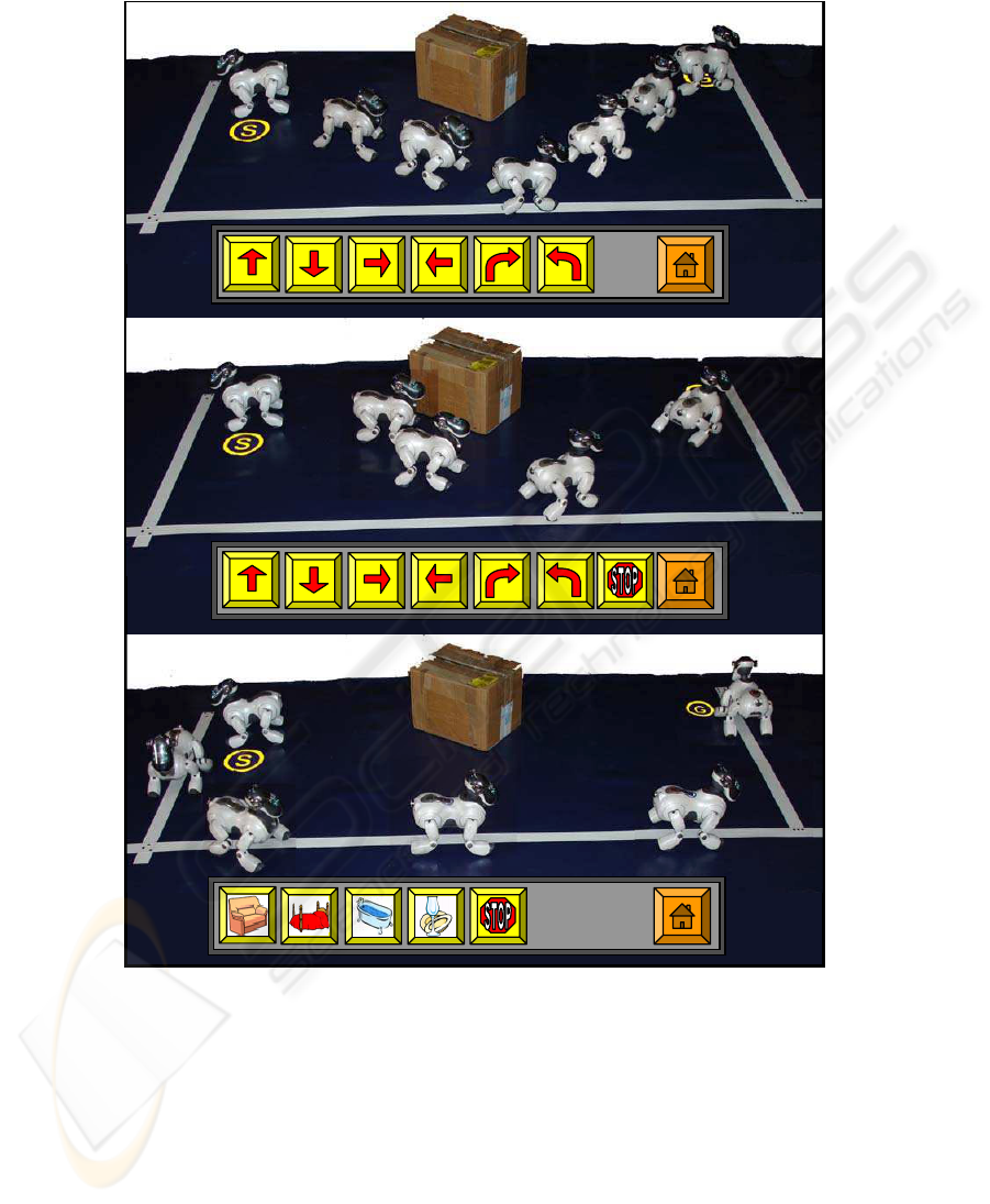
Fig.3. Comparing navigation modes: AIBO is driven from S to G with single step (above), semi-
autonomous (center) and autonomous (below) modes. The ASPICE Navigation GUIs for each
mode are also shown; in each GUI, the home button brings back to the ASPICE main GUI.
walks continuously in that direction until it receives a new command (either a new di-
rection or a stop) and concurrently uses artificial potential fields, based on the distance
sensors, to avoid obstacles. Finally, in the autonomous mode, only a target point in the
environment is assigned by the user, and the robot travels to the target (e.g., the living
84
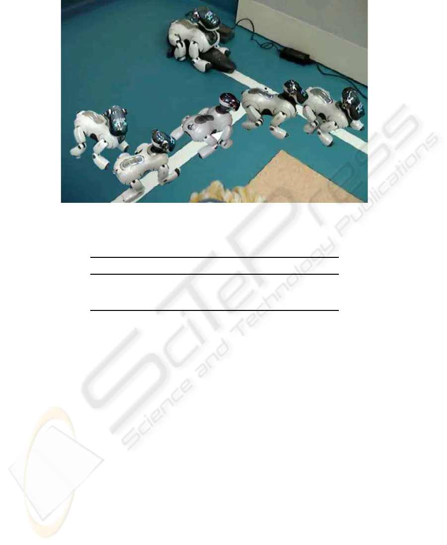
Fig.4. The battery charging experiment.
Table 1. Comparison between the three ASPICE navigation modes.
execution time (sec) user intervention (clicks)
single step 107 11
semi-autonomous 83 5
autonomous 90 1
room, the bathroom, or the kitchen). This mode is useful for quickly reaching some
important locations; it is particularly useful for severely impaired patients, which are
unable to send frequent commands. The practical implementation of the autonomous
mode is the vision-based path planner/follower presented in this paper.
In a first experiment (Fig. 3), the user is expected to drive the robot, by selecting
commands on the ASPICE GUIs, from a start point to a goal point (denoted respec-
tively by “S” and “G” on the image). The task is repeated 5 times for each navigation
mode (single step, semi-autonomous, and autonomous) and results are averaged. Com-
parison between the three modes is based on execution time and user intervention (i.e.,
number of times the user had to intervene by clicking on the GUI for updating the com-
mands). As expected, results (indicated in Table 1) confirm the qualitative properties of
the autonomous mode. Note, however, that the best choice depends not only on user’s
preference and ability but also on the specific task (e.g., position of the start and goal
points in the environment, presence and position of obstacles).
In a second experiment, autonomous battery charging is tested. This experiment
provides an additional testbed for VBN. In fact, the AIBO Charging Station is placed
near a marked crossing on the roadmap, and as soon as the battery level is low, the robot
autonomously moves to the station. The experiment is illustrated in Fig. 4. The robot
85

position at consecutive time frames is shown while it approaches the roadmap, follows
the street up to the battery charger crossing, detects it, and makes a turn in order to reach
the charging station on the basis of the plan.
6 Conclusions and Future Work
A vision-based navigation system for AIBO has been developed. This system has been
integrated in the ASPICE system, compared with the two previously designed ASPICE
navigation modes, and tested by patients in a neurorehabilitation program. For two
weekly sessions over 4 weeks, patients suffering from Spinal Muscular Atrophy type
II and Duchenne Muscular Dystrophy have been practising with the ASPICE system.
All of the patients were able to master the system and control AIBO within 5 sessions.
The average grade given by the patients to their ‘personal satisfaction in utilizing the
robot’ was 3.04 on a 5-point scale [12]. This is a very promising result, considering that
the users were originally more accustomed to using and controlling the ‘traditional’
ASPICE appliances rather than the mobile robot.
References
1. G. N. DeSouza, A. C. Kak: Vision for Mobile Robot Navigation: A Survey. In: IEEE Trans-
actions on Pattern Analysis and Machine Intelligence Vol. 24, n. 2 (2002)
2. M. Carreras, P. Ridao, R. Garcia, T. Nicosevici: Vision-based localization of an underwa-
ter robot in a structured environment. In: IEEE International Conference on Robotics and
Automation (2003)
3. M. Kabuka, A. Arenas: Position verification of a mobile robot using standard pattern. In:
IEEE Journal of Robotics and Automation, Vol. 3 n. 6 (1987) 505 - 516
4. L. W. Ching, M. K. H. Leung: SINVI: smart indoor navigation for the visually impaired. In:
8th International Control, Automation, Robotics and Vision Conference, Vol. 2 (2004)
5. A. M. Sabatini, V. Genovese, E. S. Maini: Toward low-cost vision-based 2D localisation
systems for applications in rehabilitation robotics. In: IEEE/RSJ International Conference
on Intelligent Robots and System, Vol. 2 (2002) 1355 - 1360
6. F. Cincotti, F. Aloise, F. Babiloni, M. G. Marciani, D. Morelli, S. Paolucci, G. Oriolo,
A. Cherubini, F. Sciarra, F. Mangiola, A. Melpignano, F. Davide, D. Mattia: Brain-operated
assistive devices: the ASPICE project. In: 1st IEEE/RAS-EMBS International Conference
on Biomedical Robotics and Biomechatronics (2006)
7. L. G. Roberts: Machine perception of three-dimensional solids. In: Optical and Electro-
optical Information Processing, M I T Press, Cambridge, MA (1965)
8. T. Rofer and others: Robocup 2005 German Team Technical Report, Center for Computing
Technology - Universit¨at Bremen (2005)
9. S. Wesolkowski, M. E. Jernigan, R. D. Dony: Comparison of color image edge detectors in
multiple color spaces. In: International Conference on Image Processing, Vol. 2 (2000)
10. P. I. Corke: Visual control of robots: high performance visual servoing, Research Studies
Press LTD (1996)
11. V. A. Ziparo, L. Iocchi: Petri Net Plans. In: Fourth International Workshop on Modelling of
Objects, Components, and Agents (MOCA’06), Turku, Finland (2006)
12. F. Cincotti, D. Mattia, F. Aloise, S. Bufalari, G. Schalk, G. Oriolo, A. Cherubini, M. G. Mar-
ciani, F. Babiloni: Non invasive Brain-Computer Interface systems: towards their application
as assistive technology. Submitted to Brain Research Bulletin (2006)
86
