SHAPE COMPARISON OF FLEXIBLE OBJECTS
Similarity of Palm Silhouettes
Leonid Mestetskiy
Department of Mathematical Methods of Forecasting
Moscow State university, Moscow, Russia
Keywords: Shape analysis, continuous skeleton, skeletal base, matching, circular tree, biometrical identification.
Abstract: We consider the problem of shape comparison for elastic objects presented by binary bitmaps. Our approach
to similarity measuring of such objects is based on the conception of a flexible object. A flexible object is
defined as a planar graph with a family of circles centered on graph edges. A set of admissible deformations
is connected with each flexible object. These deformations are described as a group of planar graph vertices
transforms. We define the flexible objects similarity through matching and alignment within the group of
admissible deformations. The regular method for approximation of the binary bitmap shape by the flexible
object is presented. The flexible object is designed as a subgraph of continuous skeleton of the binary
bitmap. The proposed approach is applied to a problem of palm shape recognition for personal biometrical
identification.
1 INTRODUCTION
The problem of binary bitmap shapes comparison
arises in many applications. In particular, the
problem of the palm shape recognition for
biometrical identification is reduced to it. The shape
of human hand (palm geometry) is an important
feature used for personal identification in access
control systems.
The color or the grayscale image of a palm
received by means of any device (for example, of
the web camera or the scanner) may be transformed
to the monochrome bitmap in which an object (a
palm) is presented by black pixels, and a background
– by white. But a human palm is a difficult object to
classify. The person can’t repeat the same position
of a palm even if he wants to. Two photos of the
same palm and two photos of two different palms
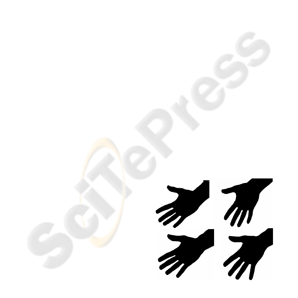
can have differences of the same range (Figure 1).
Known approaches to shape comparison of the
objects based on alignment of their outline contours
(Sederberg and Greenwood, 1992) are unsuitable for
solving these problems. These methods don’t
preserve important invariants of the palm shape –
finger’s width and curvature.
Another approach to compare general structure
features of object shapes is based on their skeletons
(Sebastian and Kimia, 2001). A skeleton is more
detailed description of topological structure of a
shape. However, it isn’t enough for comparison of
palms. The topology of skeletons of palms anyway
is almost identical. There are only 5 topologically
different skeletons of palm. But skeletons don’t
allow comparing such important features as palm’s
outlines.
The proposed approach solves this problem. We
propose a measure for human palms comparison
(and other similar elastic objects) using both this
Figure 1: The silhouettes of palms (the first row – the
same person, the second row – different persons).
390
Mestetskiy L. (2007).
SHAPE COMPARISON OF FLEXIBLE OBJECTS - Similarity of Palm Silhouettes.
In Proceedings of the Second International Conference on Computer Vision Theory and Applications - IFP/IA, pages 390-393
Copyright
c
SciTePress
features. Alignment of skeletons allows comparing
general structure of objects and deforming of their
outlines. Then measure of difference between
objects is obtained by matching of outlines.
The basis of this approach is the model of the so-
called flexible object. Such object has a shape which
can change within certain limits. The limits of these
changes are described by special group of
transforms. The transforms are organized in such a
way that some elements of the shape are fixed and
constant, and others can vary. With reference to a
palm constant elements are metacarpus and
phalanges of fingers, but changeable elements are
joints. The problem of flexible object comparing is
reduced to selection of such admissible transforms
of these objects, in which their shapes will be the
closest to one another. The difference of their shapes
in this (the closest) position is accepted as a measure
of the distinction of objects.
2 A FLEXIBLE OBJECT
Let's consider a set of points
T
on the Euclidean
plane
2
R
, which is presented by a planar graph with
tree type structure. This graph has a finite set of
vertices, and its edges are continuous lines.
We bind with each point
Tt ∈ in graph
T
some circle
t
c with the center in this point. Let’s
call this family of circles
{}
TtcC
t
∈
= , a
circular tree. A graph
T
we call an axial graph of
the circular tree. And a union
U
Tt
t
cS
∈
= of all
circles of family
C (as point sets) we call a
silhouette of the circular tree. The silhouette of the
circular tree represents a closed connected set of the
Euclidean plane
2
RS ⊂ . The outline of this set is
an envelope of the whole family of circles
C . There
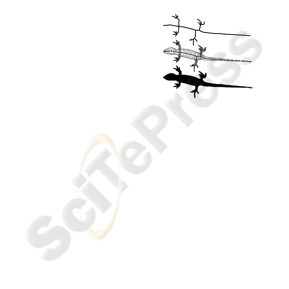
is an example of the circular tree on Figure 2. The
set
C
is infinite, bat we use its finite subset for
visualization on Figure 2 and other Figures.
Among all vertices of a circular tree we extract
some subset of the points
T
P ⊂
called bend
points. We connect a range of angles between each
couple of edges incident to bend point. We forbid
the changing a relative position of edges for the rest
vertices of the graph.
A change of angles in bend points in an
admissible range is called a deformation of a
circular tree. Such deformation implies not only the
change of an axial graph, but also moving of a
family of circles and a respective alteration of a
circular silhouette of a tree.
Let
V
be a group of deformations of a circular
tree
C . The couple of circular tree and its group of
deformations we call a flexible object
),( VCG = .
If some deformations of two circular trees make
their silhouettes coincide then these trees are called
equivalent. A shape of the flexible object is
described by a set of silhouettes of all its equivalent
circular trees.
3 THE COMPARISON OF
FLEXIBLE OBJECTS
We introduce the metrics on the set of flexible
objects in the following way. We define distance
),(
21
GG
ρ
between two flexible objects
),(
111
VCG
=
and ),(
222
VCG
=
as the minimal
distance between their circular trees on the whole set
of admissible deformations, i.e.
)](),([inf),(
221121
22
11
CvCvGG
Vv
Vv
μ
ρ
∈
∈
=
.
Here
)(
11
Cv
and
)(
22
Cv
are circular trees
1
C
and
2
C transformed by means of deformations
1
v
and
2
v , and is a measure of distance of circular
trees.
)\\(),(
122121
SSSSAreaCC ∪
=
μ
Here
1
S
and
2
S
are silhouettes of circular trees
1
C and
2
C . And ),(
21
CC
μ
is equal to the area of
Figure 2: An axial graph, a family of circles and a
silhouette of the circular tree.
SHAPE COMPARISON OF FLEXIBLE OBJECTS - Similarity of Palm Silhouettes
391
a symmetric difference of
1
S
and
2
S
minimized for
all possible variants of matching.
Thus, the problem of an estimation of similarity
of flexible objects consists in their matching on each
other and a choice of such deformation of these
objects and such matching at which the value of the
distinctions of their shapes will be minimal. With
reference to human palms it means, that it is
necessary to apply palms to each other and move
fingers in such a way that silhouettes of palms have
coincided at the greatest degree.
4 THE CONSTRUCTION OF A
FLEXIBLE OBJECT
Let it be a binary bitmap (Figure 1). A construction
of a flexible objects which approximating this
bitmap includes the following steps:
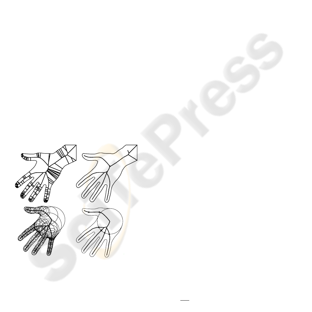
1. An approximation of the binary bitmap outline by
the minimal perimeter polygon. The polygon is a
closed path of the minimal length separating black
and white pixels on the binary bitmap (Figure 3a).
2. A construction of the continuous skeleton of the
polygon (Mestetskiy, 1998, 2006). The skeleton of
the polygon is a locus of the centers of its inscribed
maximal circles (Figure 3a). The skeleton of the
polygon with its circles forms a circular tree, and the
polygon itself is a silhouette of this tree.
3. A pruning of a skeleton to get the so-called
skeletal base of the polygon (Figure 3b).
Let
M
be a polygon, and S - a silhouette of
circular tree of a connected subgraph of its skeleton.
We will call the minimal subgraph of the skeleton, at
which a silhouette of a circular tree differs from a
polygon in the Hausdorf metrics no more than on the
given value
ε
, a skeletal base of the polygon
M
,
i.e.
ε
≤
),( SMH
.
A skeletal base has a much more simple
structure, than the skeleton of a polygon (Figure 3b)
and is more stable to noise distortions connected
with the source binary bitmap.
5 THE COMPARISON OF
SILHOUETTES OF PALMS
Let’s choose a third degree vertex of a skeletal base
graph which is incidence with the branch of the
thumb (the vertex
A
on Figure 3b). The branches of
the thumb and a wrist are crossing in this vertex. The
image of a wrist is extraneous information for palm
shape description. Therefore we delete the branch of
a wrist in the skeletal base. The obtained graph is an
axial graph of a circular tree of a flexible object
(Figure 3c). The vertex
A is a root of the circular
tree. Its circle is called “root” circle. The next third
degree vertex
B
we call “center” of a palm (Figure
3c) and its circle is called “middle” circle.
The analysis of a real skeleton of a human palm
shows, that it is enough to consider six bend points:
two points of the thumb and one point of each of the
rest four fingers (Figure 3d). We choose two bend
points (0 and 1) of maximal curvature at thumb
branch and four bend points (2-5) as crossing of
finger branches and the “root” circle.
We can estimate the distance
),(
21
GG
ρ
between two palms by more simple measure:
≤
=
∈
∈
)](),([inf),(
221121
22
1
11
CvCvGG
Vv
Vv
μ
ρ
),(
ˆ
)](,[inf
21221
22
GGCvC
Vv
ρ
μ
=
≤
∈
The estimation
),(
ˆ
21
GG
ρ
represents a measure
of distance of flexible objects
1
G
and
2
G
, received
by a static position of
1
G and a deformation of
2
G .
Alignment of two palms is carried out by the
following steps.
1. Coincidence of centers of “middle” circles
(vertices
B
in Figure 3d).
2. Coincidence of directions from the centers of
“middle” circles to the centers of “root” circles
(vectors
B
A
in Figure 3d).
(a)
(b)
(c)
(d)
A
B
0
1
2
3
4
5
A
B
Figure 3: Approximation of a palm by flexible object: (a)
the minimal perimeter polygon and its skeleton, (b) the
skeletal base, (c) the circular tree, (d) banding points.
VISAPP 2007 - International Conference on Computer Vision Theory and Applications
392
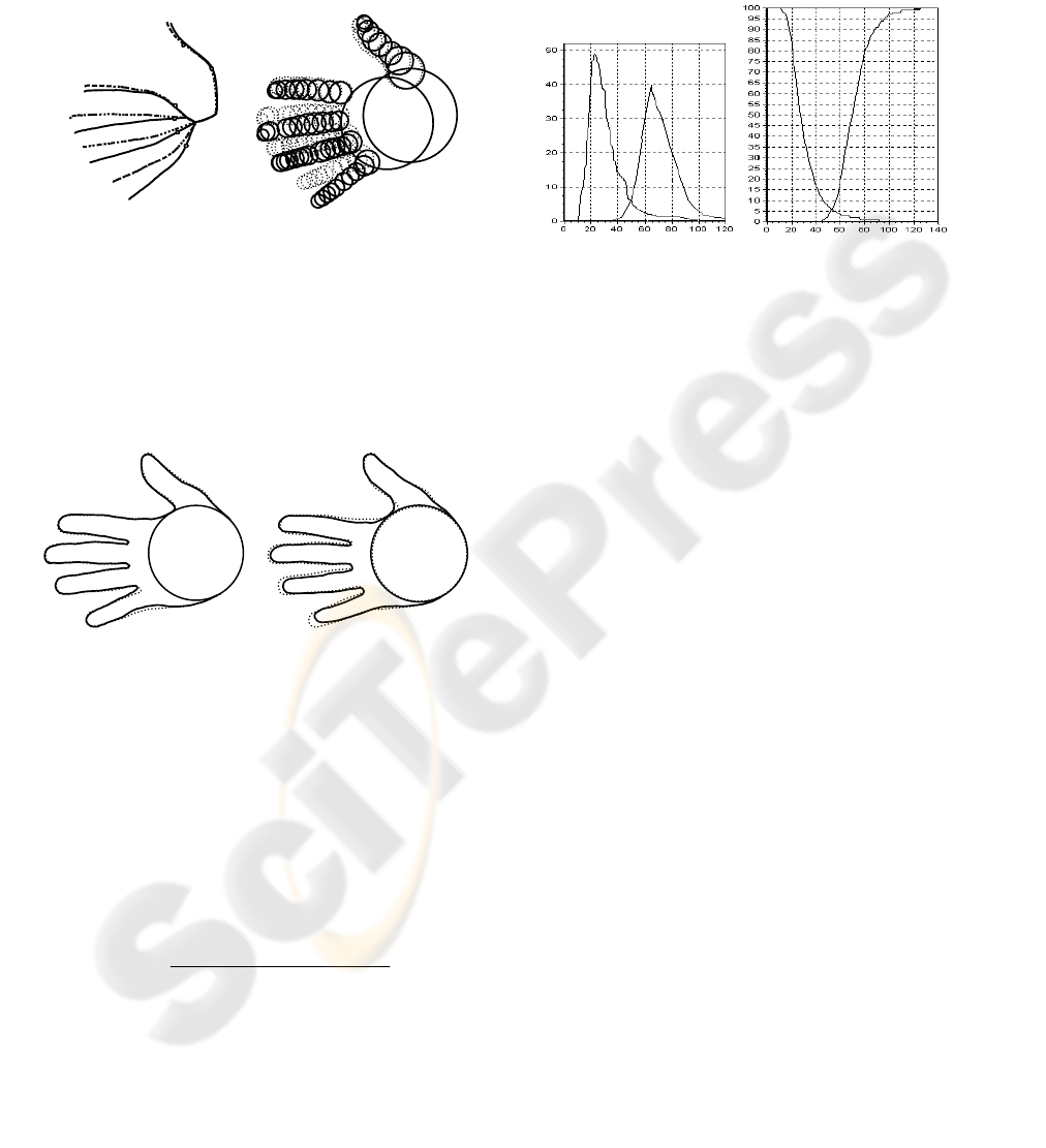
Figure 6: Left – distance distribution to the nearest palm,
right – classification errors (FRR – left curve, FAR – right
curve).
3. Deformation of the axial graph of the second palm
for coincidence with the axial graph of the first palm
(Figure 4). For that we “rotate fingers” of the second
palm (branches of axial graph) around bending
points. The Hausdorf metrics can be used as a
measure of coincidence of these branches.
4. Construction of circular tree silhouettes as
envelopes of a family of circles.
5. Comparing of silhouettes (Figure 5). The effective
algorithm for computation of the areas of a
symmetric difference is designed with the help of
methods of computational geometry.
The computing experiment was carried out for
testing of proposed method. The data base of 1662
bitmaps of 320 palms (4-6 images per person) has
been used in this experiment. All images 640×480
were obtained for the same conditions (camera,
distance, brightness). The approximating flexible
objects have been constructed for each of these
bitmaps. The measure of distance between
silhouettes
1
S and
2
S was computed as
1000
)(
)\\(
),(
1
1221
21
⋅
∪
=
SArea
SSSSArea
SS
ρ
.
The left diagram on Figure 6 shows the
distribution of distances to the nearest sample of the
same person (left curve), and of different people
(right curve). Such distance enables to construct a
classification rule by the nearest neighbor. The
diagram of classification errors for different values
of the threshold is shown on Figure 6 (right).
The running time for binary bitmap
approximation of one bitmap by the flexible object
is 15 msec, and for two palms comparison is 0.5
msec using Intel processor 1.3 GHertz.
6 CONCLUSIONS
The combination of two constructions – an outline
and a skeleton – opens up opportunities for the
comparison of objects which don’t have strictly
fixed shapes using a matching method. The
proposed method is well adjusted with common
sense, is easily visualized and allows efficient
implementation.
ACKNOWLEDGEMENTS
The author thanks the Russian Foundation for Basic
Researches, which has supported this work (grant
05-01-00542).
REFERENCES
Mestetskiy, L., 1998. Continuous skeleton of binary raster
bitmap. In Graphicon’98, International Conference on
computer graphics, Moscow, in Russian.
Mestetskiy, L., 2006. Skeletonization of a multiply
connected polygonal domain based on its boundary
adjacent tree. In Siberian journal of numerical
mathematics, vol.9, N 3, 2006, 299-314, in Russian.
Sebastian, T., Kimia, B., 2001. Curves vs skeletons in
object recognition. In Proceedings of International
Conference on Image Processing, Thessaloniki,
Greece.
Sederberg, T., Greenwood, E., 1992. A physically based
approach to 2-D shape blending. In Computer
Graphics 26(2), 25-34.
(а) (б)
(а) (б)
Figure 4: Deformation of the circular tree:
(a) rotation of branches, (b) moving of circles.
Figure 5: Comparison of silhouettes: (a) images of the
same palm, (b) palms of different persons.
SHAPE COMPARISON OF FLEXIBLE OBJECTS - Similarity of Palm Silhouettes
393
