
CLEAR IMAGE CAPTURE
Active Cameras System for Tracking a High-speed Moving Object
Hiroshi Oike, Haiyuan Wu, Chunsheng Hua and Toshikazu Wada
Department of Computer and Communication Sciences, Wakayama University, 930 Sakaedani, Wakayama City 640-8510, Japan
Keywords:
Object tracking, Binocular Active camera, Clear image.
Abstract:
In this paper, we propose a high-performance object tracking system for obtaining high-quality images of a
high-speed moving object at video rate by controlling a pair of active cameras that consists of two cameras
with zoom lens mounted on two pan-tilt units. In this paper, “high-quality image” implies that the object
image is in focus and not blurred, the size of the object in the image remains unchanged, and the object is
located at the image center. To achieve our goal, we use the K-means tracker algorithm for tracking objects in
an image sequence captured by the active cameras. We use the results of the K-means tracker to control the
angular position and speed of each pan-tilt-zoom unit by employing the PID control scheme. By using two
cameras, the binocular stereo vision algorithm can be used to obtain the 3D position and velocity of the object.
These results are used in order to adjust the focus and zoom. Moreover, our system allows the two cameras
to gaze at a single point in 3D space. However, this system may become unstable when the time response
deteriorates by excessively interfering in a mutual control loop or by strict restriction of the camera action. In
order to solve these problems, we introduce the concept of reliability into the K-means tracker, and propose a
method for controlling the active cameras by using relative reliability. We have developed a prototype system
and confirmed through extensive experiments that we can obtain focused and motion-blur-free images of a
high-speed moving object at video rate.
1 INTRODUCTION
It is likely that a captured image may include a blurred
object if the object is moving at a high speed and the
camera is relatively stable. In such cases, we will lose
important information (e.g., the object’s edge and col-
ors), which is required in several computer vision re-
searches. With regard to the problems in recognizing
and understanding high-speed moving objects, cap-
turing a high-quality image is as important as analyz-
ing the captured object image.
To solve these problems, we propose a high-
performance object tracking system for obtaining
high-quality images of a high-speed moving object at
video rate.
1.1 Related Work
Related works on active vision tracking systems have
been developed by many researchers. The following
are examples of some representative researches.
(a) Active tracking system using vision chip (Ko-
muro et al., 2003).
(b) Active tracking system using high-speed cameras
(Okada et al., 2004).
(c) Object detection and tracking system using fixed
viewpoint pan-tilt-zoom camera (Matsuyama
et al., 2000).
(d) Active tracking system using binocular stereo
heads (Bjorkman and Eklundh, 2002).
(e) Binocular pursuit system (Coombs and Brown,
1993).
(f) Visual closed-loop system using Dynamic effect
(Corke and Good, 1996).
The system in (a) may be the fastest driven track-
ing system in the world. Since it uses a special sensor
(Vision Chip), the resolution of the obtained image
is quite low. Further, the system can only pursue an
object in an illumination-controlled indoor room.
The system in (b) was constructed using a high-
speed camera, and can thus only obtain very dark im-
ages due to the short exposure time.
The system in (c) uses an fixed viewpoint pan-
tilt-zoom camera (hereafter referred to as an FV-PTZ
94
Oike H., Wu H., Hua C. and Wada T. (2007).
CLEAR IMAGE CAPTURE - Active Cameras System for Tracking a High-speed Moving Object.
In Proceedings of the Fourth International Conference on Informatics in Control, Automation and Robotics, pages 94-102
DOI: 10.5220/0001647600940102
Copyright
c
SciTePress
camera) similar to our system. Due to the use of back-
ground subtraction as the object tracking algorithm,
the active camera must stop its motion for image cap-
ture. Therefore, moving target images captured by
this system may appear blurred or out of focus. More-
over, the tracking performance of this system is a few
dozen degrees per second.
System (d) was constructed using binocular cam-
eras similar to our system. The advantage of this sys-
tem is that it seldom fails in tracking a target that is
at a different depth when compared to its surrounding
objects. This is a fast-driven system; however, it is
very expensive because it uses very complex special
hardware.
In (e), the system was constructed using binocu-
lar camera head fixed on the robot arm, and In (f), it
presented the effect of the introduction the dynamic
control (like feed-forward control) into closed-loop
tracking system. In these manuscripts, the methods
of object tracking are not described clearly.
As is evident from the details stated above, the re-
lated works require complex, expensive, and special
hardware; in addition, their operation is seldom sta-
ble in a real environment. Moreover, their systems
obtain target object images regardless of their quality,
because the architecture of these systems is based on
the concept of only tracking the object.
1.2 Our Approach
In our system, we use two computers and video cam-
eras that are available in the market to obtain the ob-
ject image, track the target object, and control the ac-
tive cameras at 30 fps. In our system, the camera
is controlled such that it moves at the same angular
speed and direction as the target object. Therefore, we
can obtain an image with a blurred background and
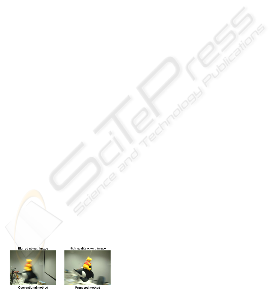
clear target at the image center (Fig.1). Additionally,
we use binocular active cameras to track the object.
We can then estimate the 3D position and velocity of
the object. The 3D information can be used for ad-
justing the focus and zoom of the camera. Therefore,
we can obtain target images that are clearer than those
Figure 1: Obtained by conventional method (left) and pro-
posed method (right).
obtained by using only a single active camera. The re-
quirements for our system are as follows:
(1) binocular active cameras to focus their optic axis
on a point in 3D space
(2) target to appear at the center of the images
This is because condition (1) helps us to avoid
the contradiction between detection with two cam-
eras. Epipolar geometry can work stably only if there
is no contradiction between the two cameras.
Condition (2) is required because the view angle
will become narrow when zooming in and the target
will easily escape from the image. In such cases, the
object tracking may completely fail, and thus, there
will be no means to control the cameras.
In fact, it is difficult to estimate the absolute cor-
rect epipolar line because of the errors in object track-
ing or estimation of camera directions. The system
becomes unstable if it is controlled according to an in-
correct epipolar line. Further, the system may become
unstable and lose its smoothness if the time response
deteriorates under the influence of excessive interac-
tions between the two control loops, or if the actions
of the cameras are overly restricted. If the tracking
system’s action is not smooth, the target in the im-
age will appear blurred and the accuracy of the object
tracking will deteriorate. Therefore, the control of the
active cameras will become increasingly unstable. As
previously described, to focus the optic axis of two
cameras on one 3D point, we must solve the follow-
ing problems.
(A) The information sent from the other camera may
be incorrect or of low accuracy if a tracking failure
occurs.
(B) Excessive constraint from the other camera will
make the tracking system’s action unstable.
The conventional related studies on active vision
tracking systems do not mention the methods for con-
trolling the binocular active camera with an emphasis
on the quality of the captured images by solving prob-
lems (A) and (B).
Therefore, in this paper, we have proposed a new
method for solving these problems and constructing
a high-speed-tracking active camera system, that can
continuously obtain high quality images. Our system
can automatically control the direction, zoom, and
focus of the two cameras to focus on a point in 3D
space.
To solve problem (A), we introduce the concept
of reliability into the K-means tracker and propose a
method to constrain the camera action by using this
reliability, which is based on the calculation of the
distance from the K-means clusters.
CLEAR IMAGE CAPTURE - Active Cameras System for Tracking a High-speed Moving Object
95
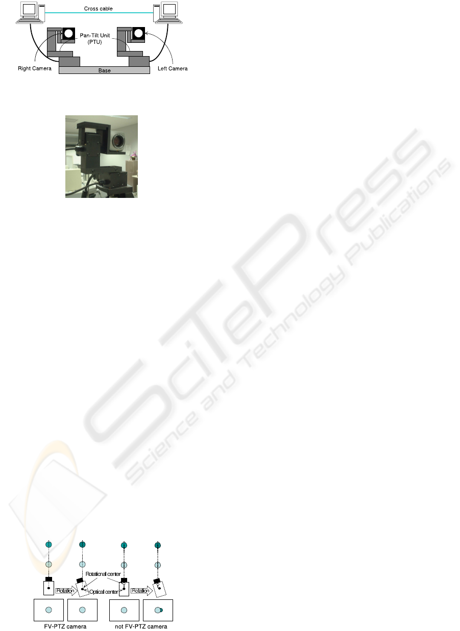
Figure 2: Construction of high-speed-tracking active cam-
eras.
Figure 3: FV-PTZ camera(Active camera).
To solve problem (B), we propose a method for
determining the level of constraint with a relative re-
liability.
By using our proposed methods, the binocular ac-
tive cameras can be smoothly controlled and their op-
tic axes can intersect at a point in 3D space.
2 CONSTRUCTION OF THE
PROPOSED SYSTEM
We construct our high-speed-tracking active cameras
with two active cameras and two computers (Fig.2).
The two computers can communicate with each other
and share their observations.
For the active camera in our proposed system, we
employ a FV-PTZ camera (Fig.3). This camera is cali-
brated such that its optical center corresponds with the
point of intersection of the pan and tilt axes. There-
fore, the optical center of the FV-PTZ camera does
not move if the pan or tilt angle is changed (Fig.4).
Therefore, by using this camera, we can ignore the
movement of the optical center. As a result, it is easy
Figure 4: Particularity of FV-PTZ camera.
to estimate the angular velocity of the target from the
captured image and represent the target velocity by
the angular velocity of the optical center.
In our system, since two cameras are fixed on the
base, as shown in Fig.2, the distance between the
cameras is constant. Therefore, we can only consider
the rotational relationship between the two cameras
and ignore the translation of the optical center.
3 ANALYSIS OF THE OBJECT
TRACKING ALGORITHM ON
THE IMAGE
Numerous powerful algorithms for object tracking
have been developed, such as Condensation(Isard and
Blake, 1998), mean-shift(Comaniciu et al., 2003) and
K-means tracker(C. Hua and Wada, 2006a; C. Hua
and Wada, 2006b).
Condensation is a very robust algorithm that al-
lows for ambiguity in the target position in the image.
However, it cannot accurately estimate the target po-
sition because of this ambiguity.
For controlling the direction of the active cam-
eras to track a moving object, the tracking algorithm
must output a unique result but not an ambiguous
one. Thus, we consider the mean-shift and K-means
tracker algorithms to be suitable for our system.
Authors of mean-shift algorithm claim that it can
adapt to variations in the target shape, color distribu-
tion, and size. However, through our experiments, we
found that tracking becomes unstable if the target size
varies greatly. Another problem is that when the tar-
get is monochromatic and in the plan shape, the mean-
shift algorithm becomes sensitive to the color shift.
We have developed a K-means tracker algorithm
that utilizes K-means clustering by using both the
positive samples of the target and the negative sam-
ples surrounding the target. In this algorithm, the
target feature is composed of the position as well as
its color because the clustering is performed in a 5D
space spanned by 3D color and 2D position param-
eters. This implies that this algorithm can adapt to
not only target position but also the color shift of the
target. Therefore, it can adapt to the shift in the illu-
mination environment caused by changing the camera
direction.
Another feature of the K-means tracker is that it
can adapt to variations in the target shape and size in
the image since it uses a variable ellipse model.
Thus, K-means Tracker is the most suitable algo-
rithm for the active vision tracking system.
ICINCO 2007 - International Conference on Informatics in Control, Automation and Robotics
96
3.1 Summary of K-means Tracker
In the K-means tracker, robust object tracking is re-
alized by using a variable ellipse model that is up-
dated in each frame according to the clustering re-
sults. The pixels on the variable ellipse contour are
defined as the representative non-target samples, and
the area within the ellipse is the target search area.
In the first frame, we manually select some target
cluster centers whose number is roughly the same as
the number of colors contained by the target. In ad-
dition, we select one non-target cluster center b on
the background for the tracking system. Then, the se-
lected non-target center and the centroid c of the tar-
get centers will constitute the initial variable ellipse
model in the form of a circle. The distance kc − bk is
the radius of this circle.
3.1.1 Clustering in the 5d Feature Space
To represent the properties of the target features in
the K-means Tracker, each pixel in an image is de-
scribed by a 5D feature vector f = [k p]
T
, where,
k = [Y U V ]
T
describes the color similarity and
p = [x y]
T
describes the position approximation of
the pixel. The feature vector of the i th target cluster
center is represented as follows:
f
T
(i) = [k
T
(i) p
T
(i)]
T
(i = 1 ∼ n). (1)
The feature tor of the j th non-target cluster center on
the ellipse contour is represented as follows:
f
N
(j) = [k
N
(j) p
N
(j)]
T
(j = 1 ∼ m). (2)
Here, n and m describe the number of cluster center
of target and non-target, respectively.
To distinguish whether pixel u belongs to the tar-
get center or not, we calculate the distances from f
u
to
the target and non-target cluster centers, respectively.
d
T
(f
u
) = min
i=1∼n
{kf
T
(i) − f
u
k
2
} (3)
d
N
(f
u
) = min
j=1∼m
{kf
N
(j) − f
u
k
2
} (4)
Here, within the search area, f
u
describes the feature
vector at pixel u, d
T
(u) and d
N
(u) describe the dis-
tances from f
u
to its nearest target cluster center and
nearest non-target cluster center, respectively.
If d
T
(f
u
) < d
N
(f
u
), the pixel is detected as a tar-
get pixel; otherwise, it is a non-target pixel.
3.1.2 Updating Variable Ellipse Model
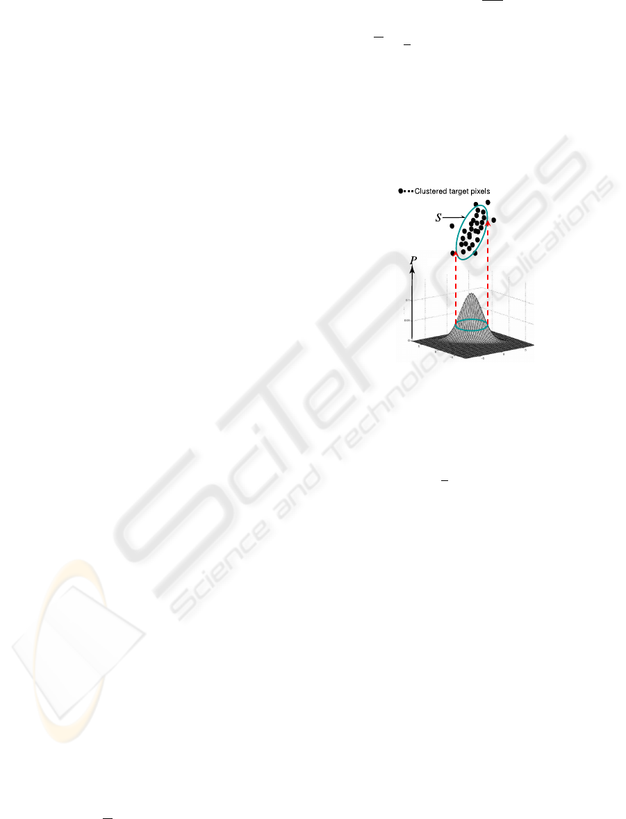
To estimate the search area represented as a variable
ellipse, we represent the equation of ellipse parame-
ters as a relation of the Mahalanobis distance and the
Gaussian probability density function.
[y − c]
T
Σ
−1
[y − c] = J (5)
Where,
J = −2 ln(1 −
P
100
) (6)
Σ =
1
e
X
y∈S
[y − c][y − c]
T
. (7)
Equations (5), (6), and (7) indicate that the search
area ellipse will contain P % of the target pixels exist-
ing within the ellipse when applying Gaussian prob-
ability function is applied to fit to the set of target
points (Fig. 5). ). This has the added effect of re-
moving outlying pixels.
Figure 5: Estimation of the ellipse parameter by using Ma-
halanobis distance and Gaussian probability density func-
tion.
The center c of the variable ellipse at the next
frame is calculated as follows:
c =
1
e
X
y∈S
y. (8)
Here, S describes the pixel set inside the ellipse; e de-
scribes the number of target pixels inside the ellipse;
and y = [y
x
, y
y
]
T
describes the target pixels.
In our system, we use c to represent the target cen-
ter. By updating c in every frame, our system can
track the target and estimate its angular velocity.
4 PROCESS FLOW
The K-means tracker discriminates each pixel within
the search area into a target and non-target pixel. In
our method, based on this discrimination, we propose
the concept of reliability into the K-means tracker.
The reliability represents how similarly each pixel be-
longs to each target cluster. With this reliability, our
proposed system can determine which camera tracks
the target more correctly and restrain the action of the
camera with a lower reliability based on the output of
the higher one.
CLEAR IMAGE CAPTURE - Active Cameras System for Tracking a High-speed Moving Object
97
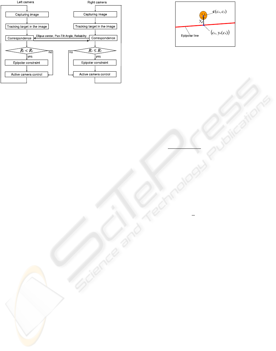
Figure 6: Flow chart of the our system.
In Fig.6, we show the flowchart of our proposed
active camera system where the constraint on the
camera action is based on the reliability. The relia-
bility of the left and right cameras is described by R
l
and R
r
, respectively. The left and right active cam-
eras can be independently controlled using the result
of K-means tracker. In such cases, each camera can
independently track the target, but it cannot automat-
ically control the zoom and focus.
Our system tracks the target in the images cap-
tured from both cameras by using the K-means
tracker. It then estimates the target position in the
each image. With this position information, the di-
rection from each optical center to the target can be
calculated.
With the result of K-means tracker, we can calcu-
late the reliability of each camera. We can then esti-
mate the epipolar line on the lower reliability camera
according to the target position in the image captured
by the higher reliability camera. The ellipse center in
the image taken from the lower reliability camera is
constrained on the estimated epipolar line. Since the
optical axis of the active camera is controlled based on
the target position in the image, the optical axis of the
active camera with the lower reliability is constrained
on the estimated epipolar line. If the optical axis con-
strains the ellipse position excessively, the FV-PTZ
unit response is lost; the velocity and direction of the
active cameras will then be different from those of the
tracked target. Due to these reasons, the tracking sys-
tem may easily become unstable.
To solve this problem, we propose a method in
which the ellipse position is not completely con-
strained on the epipolar line but is weighted by the
higher reliability value of the higher reliability cam-
era.
Figure 7: Ellipse position constraint on the epipolar line
along the vertical direction.
4.1 Calculation of the Reliability
The reliability of each camera is calculated according
to the result of the distance calculated in the feature
space of the K-means tracker.
In this paper, u represents a pixel in the search area
restricted in an ellipse. r(u) represents the reliabil-
ity of u and describes the similarity of target clusters.
r(u) is calculated as follows:
r(u) =
(
d
N
(f
u
)
d
N
(f
u
)+d
T
(f
u
)
(d
T
(f
u
) < d
N
(f
u
))
0 (otherwise).
(9)
Here, the distances of d
T
(f
u
) and d
N
(f
u
) are calcu-
lated by Eq.(3) and Eq.(4), respectively.
Further, R is the reliability of all pixels in the
search area restricted in the same ellipse, and is cal-
culated by
R =
1
e
C
X
u=1
r(u). (10)
Here, C is the number of pixels in the ellipse and e is
the number of target pixels. To correct the difference
between ellipse size of the two cameras, R is normal-
ized by e.
4.2 Constraint Ellipse on Epipolar Line
by using Relative Reliability
In our proposed system, based on the results of track-
ing with the high-reliability camera, the ellipse po-
sition is constrained on the epipolar line only in the
low-reliability camera.
In many cases, the two epipolar lines drawn in
each image become horizontal because the active
cameras are fixed on the horizontal base. Therefore,
the ellipse position is constrained on the epipolar line
only along the vertical direction.
In Fig.7, y
d
is the distance along the vertical di-
rection from the ellipse center c = (c
x
, c
y
) to the
epipolar line. y
e
(x) is the vertical coordinate of the
intersection point of the epipolar line and the verti-
cal line that passes through the ellipse center c. y
d
is
ICINCO 2007 - International Conference on Informatics in Control, Automation and Robotics
98
calculated as follows:
y
d
= y
e
(c
x
) − c
y
. (11)
If the ellipse position is constrained on the epipolar
line, only with y
d
for a single frame, the camera action
may become unstable, as described above. Thus, in
our system, we let the constraint ∆y be calculated by
∆y = wy
d
. (12)
Here, w is the weight of the relative reliability and is
determined by
w =
R
b
R
l
+ R
r
(R
b
= max{R
l
, R
r
}). (13)
Here, R
l
and R
r
are calculated by Eq.(10). If the
reliability of the lower reliability camera equals zero,
w becomes 1, and if the reliability of the two cameras
are identical, w becomes almost 0.5.
5 ACTIVE CAMERA CONTROL
In order to controlling the FV-PTZ unit, we employ
the PID control scheme.
P component is assigned as the target angular ve-
locity represented as follow:
v
objt
= v
Robjt
+ v
camt
. (14)
Here, v
Robjt
and v
camt
represent the relative angular
velocity of the object and the rotational angular veloc-
ity of the active camera at time t. v
Robjt
is computed
by using angle between the object center and the im-
age center which is represented as s.
v
Robjt
=
s
t
− s
(t−1)
∆t
(15)
Here, ∆t represents the time between continuous two
frames. The system can know v
camt
by response from
PTU controller.
I component rectifies the difference between the
object center and the image center and it calculated
by follow:
v
dxt
=
s
t
∆t
. (16)
Because the command format for PTU is angular ve-
locity, I component has to be transformed to angular
velocity form.
D component is represented by the angular accel-
eration calculated as follow:
a
t
=
v
objt
− v
obj(t−1)
∆t
. (17)
Thus, the PID control scheme is suitable for si-
multaneously controlling the angular speed and po-
sition of the pan-tilt unit. Therefore, the PID-based
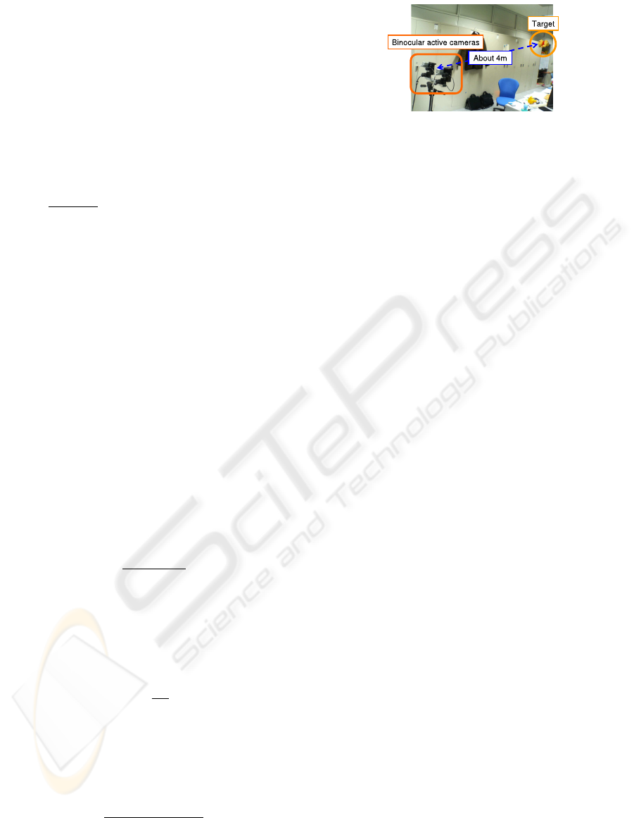
Figure 8: The Environment of Comparative Experiments.
pan-tilt control is effective for motion synchroniza-
tion between the target and the active camera.
The control value v
u
is computed by
v
ut
= K
p
v
objt
+ K
i
v
dxt
+ K
d
a
t
∆t.
(18)
Furthermore, using the proposed system, we can ob-
tain 3D position information of the target because two
cameras are used. Therefore, the system can automat-
ically control each camera’s zoom and focus based on
the estimated distance from the cameras. In our sys-
tem, zoom is controlled for keeping the resolution of
the target appearance.
Focus is controlled based on the relationship be-
tween the distance and the best focus value which has
already been known by pre-experiment.
6 EXPERIMENT
6.1 Comparative Experiment
We carried out comparative experiments to verify the
performance of our proposed tracking system by com-
paring it with two other methods.
Method 1: Epipolar constraint is not used to
control the active cameras. This implies that the
two active cameras are controlled independently.
Method 2: The epipolar constraint is applied
to the camera with the lower reliability and the
weight factor is set as w = 1.
Method 3: The proposed method. The epipolar
constraint is applied to the camera with the lower
reliability and the weighted quantity of the con-
straint with a relative reliability is used.
Figure 8 shows the environment in which the com-
parative experiments were performed.
The target object is a doll suspended from the ceil-
ing and swinging like a pendulum. In this experiment,
the doll was at a distance of about 4 meters from the
active cameras in the initial state.
We show a part of the sequence obtained in this
experiment as captured by the right camera in Fig.9.
CLEAR IMAGE CAPTURE - Active Cameras System for Tracking a High-speed Moving Object
99
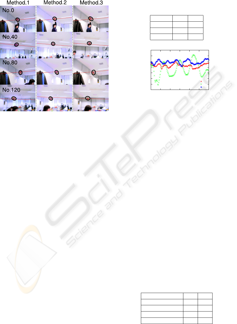
Figure 9: Several frames of the sequence obtained in the
experiment.
To compare the three methods impartially, we al-
low the tracked target to assume the same motion in
each experiment. We release the target object at the
same height and allow it to move with an inertial mo-
tion three times.
The red lines in Fig.9 indicate the visual line of
the left camera projected onto the image of the right
camera.
To evaluate the performance of: Controlling the
binocular active camera to make the direction of the
cameras intersect at a point in 3D space, we used the
error of the visual lines of the cameras and compared
this among the three methods. As an evaluation mea-
sure, the error between each normalized vector of the
epipolar planes calculated based on each camera was
used. If the visual lines of the cameras perfectly in-
tersect at a point, the error between each normalized
vector will be zero.
We tracked the target object during 120 frames
and calculated the absolute average and deviation of
the errors between each normalized vector. Fig.10
shows a graph that indicates the error between each
normalized vector with time and the absolute average
and deviation of the error is shown in Table 1.
The error between each normalized vector in
Method 3 was less that in Method 1. Therefore, our
proposed method effectively achieves our goal. The
error between each normalized vector in Method 2
was greater than that in the other two methods.
This is because the control of the directions of the
active cameras became unstable since they could not
respond quickly when the estimated ellipse center was
constrained on the epipolar line. Next, we demon-
Table 1: Average and deviation of the error between each
normalized vector(unit: degree).
Method Ave Dev
1 0.84 0.28
2 1.06 0.71
3 0.33 0.20
-4
-3
-2
-1
0
1
2
3
0 20 40 60 80 100 120
Error(degree)
frame(Time)
Method3
Method2
Method1
Figure 10: The error between each normalized vector.
strate the target pursuit of our proposed system. To
evaluate it, we use the difference between the rota-
tional velocities of the target and the active camera.
This is calculated as the difference between the target
ellipse center axis of the image in the current frame
and that in the previous frame. We call this difference
position error between frames. This number is equal
to zero if the rotational velocity of the target equals
that of one of the active cameras. On the contrary, if
there is a difference between the velocities, the posi-
tion error between frames increases.
In Table 2, we show the average and deviation
of the absolute value of the position error between
frames of both the cameras when experiments were
conducted using Method 1 and Method 3.
The vertical deviation in Method 3 was marginally
greater than that in Method 1 while the horizontal val-
ues were almost constant.
According to the result of this experiment, we ver-
ified that the tracking performance that uses the pro-
posed epipolar constraint method will not degrade.
6.2 Tracking a Human Head
Figure 11 show several sequential frames that track
a human head. The person in these frames walked
Table 2: The average and deviation of the absolute value of
the position error between frames (unit: degree).
Method:direction Ave Dev
1:horizontal 3.8 2.7
3:horizontal 3.7 2.5
1:vertical 3.5 2.2
3:vertical 3.8 2.9
ICINCO 2007 - International Conference on Informatics in Control, Automation and Robotics
100
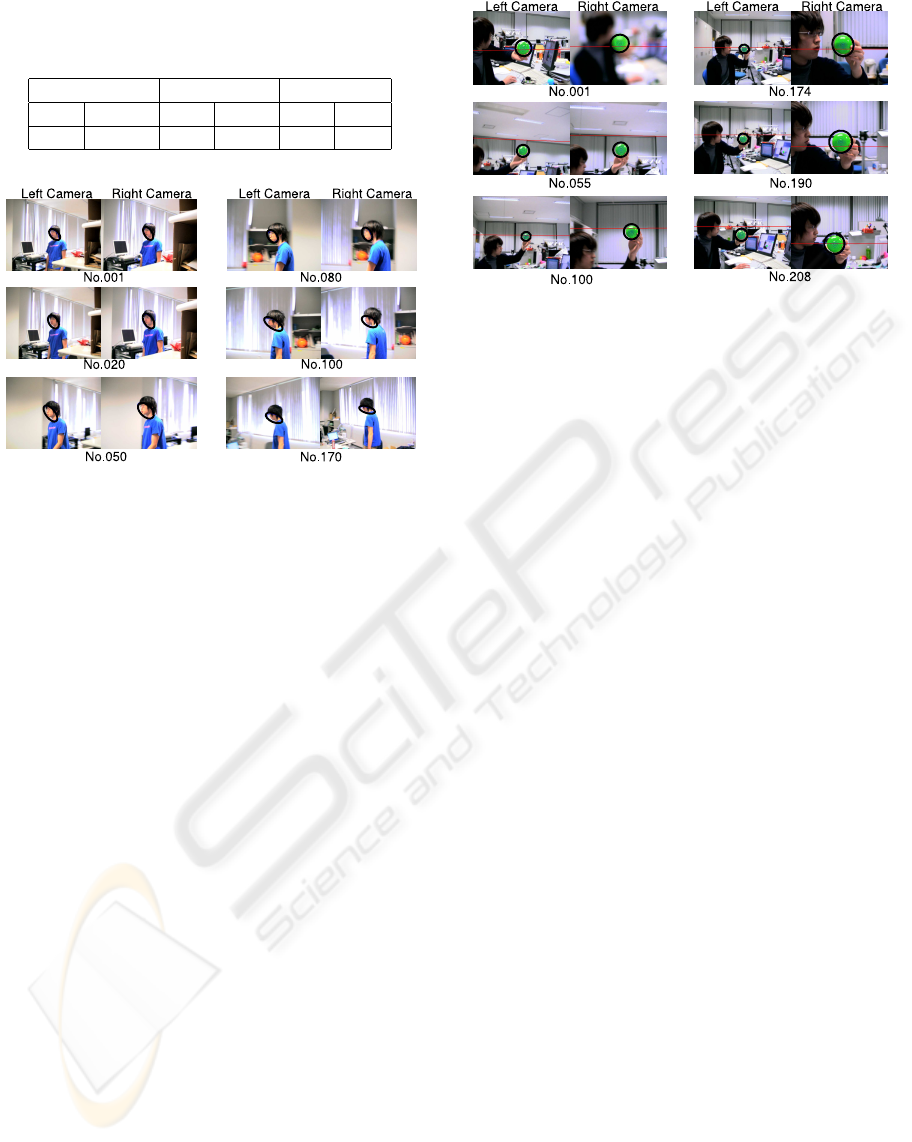
Table 3: The average and deviation of the absolute value of
the horizontal position error between frames in the human
head tracking experiment (unit: degree).
Right camera Left camera Summary
Ave Dev Ave Dev Ave Dev
2.4 2.6 2.1 2.2 2.2 2.4
Figure 11: Several frames in the sequence that track a hu-
man head.
straight from right to left. In frame no. 080, the per-
son was closest to the cameras.
Table 3 shows the average and deviation of the ab-
solute values of the horizontal position error between
frames in the human head tracking experiment.
Because both the velocity and acceleration of the
target were less than those in experiment 6.1, the
tracking error was smaller.
6.3 Zoom and Focus Control
Figure 12 shows several sequential frames that track
a ball with automatic zoom-focus control. The pur-
pose of the zoom and focus control is to maintain the
tracked target in focus with constant resolution.
In order to test the effect of focus control, the tar-
get was defocused in the first frame. By comparing
the images of the right camera with those of the left
camera, it was observed that the size of the ball in the
left camera images became smaller than that in the
first frame. In contrast, the ball size in the right cam-
era images remained unchanged because of the zoom
control, which automatically zoomed in when the ball
moved away from the camera.
Moreover, the defocus state in the first frame was
automatically canceled by the focus control and the
ball in the image was focused.
Figure 12: Several frames in the sequence for tracking a
target in the zoom-focus control experiment.
7 CONCLUSION
In this paper, we have developed a high-performance
object tracking system that can successfully capture
high-quality images of a high-speed moving object at
video rate. To increase the robustness and accuracy of
object tracking in the video image, we introduced the
concept of reliability into the K-means Tracker. In or-
der to follow the movement of the object, two active
cameras were controlled so that the object appeared
at the center of the image plane. This was realized by
positioning the optic axis of the two active cameras at
the center of the object in the 3D space. To achieve
this, we proposed the concept of relaxed epipolar con-
straint between the two cameras based on the reliabil-
ity of object tracking and applied it to the control loop
of the two active cameras. The extensive comparative
experimental results demonstrated the usefulness and
the effectiveness of our proposed method.
ACKNOWLEDGEMENTS
This research is partially supported by the Min-
istry of Education, Culture, Sports, Science and
Technology, Grant-in-Aid for Scientific Research
(A)(2)16200014, and (C)(2) 18500131.
REFERENCES
Bjorkman, M. and Eklundh, J. O. (2002). Real-time epipo-
lar geometry estimation of binocular stereo heads.
PAMI, 24-3:425–432.
C. Hua, H. Wu, Q. C. and Wada, T. (2006a). Kmeans
tracker: A general tacking algorithm for tracking peo-
ple. Journal of Multimedia, 4.
CLEAR IMAGE CAPTURE - Active Cameras System for Tracking a High-speed Moving Object
101

C. Hua, H. Wu, Q. C. and Wada, T. (2006b). Object track-
ing with target and background samples. IEICE (ac-
cepted).
Comaniciu, D., Ramesh, V., and Meer, P. (2003). Kernel-
based object tracking. PAMI, 25-5:564–577.
Coombs, D. and Brown, C. (1993). Real-time binocular
smooth pursuit. International Journal of Computer
Vision, 11-2:147–165.
Corke, P. I. and Good, M. C. (1996). Dynamic effects
in visual closed-loop systems. IEEE transaction on
Robotics Automation, 12-5:671–683.
Isard, M. and Blake, A. (1998). Condensation-conditional
density propagatiojn for visual tracking. IJCV, 29-
1:5–28.
Komuro, T., Ishii, I., Ishikawa, M., and Yoshida, A. (2003).
A digital vision chip specialized for high-speed tar-
get tracking. IEEE transaction on Electron Devices,
50:191–199.
Matsuyama, T., Hiura, S., Wada, T., Murase, K., and Yosh-
ioka, A. (2000). Dynamic memory: Architecture for
real time integration of visual perception, camera ac-
tion, and network communication. CVPR, pages 728–
735.
Okada, R., Oaki, J., and Kondo, N. (2004). High-speed
computer vision system for robot. TOSHIBA Review
(in Japanese), 59-9:29–32.
ICINCO 2007 - International Conference on Informatics in Control, Automation and Robotics
102
