
USEFUL COMPUTER VISION TECHNIQUES
FOR A ROBOTIC HEAD
O. Deniz, M. Castrillon, J. Lorenzo and L. A. Canalis
Instituto Universitario de Sistemas Inteligentes y Aplicaciones Numericas en Ingenieria
Universidad de Las Palmas de Gran Canaria
Edificio central Parque Cientifico-Tecnologico, Campus de Tafira
35017 - Las Palmas - Spain
Keywords:
Social robotics, sociable robot, person detection, omnidirectional vision.
Abstract:
This paper describes some simple but useful computer vision techniques for human-robot interaction. First,
an omnidirectional camera setting is described that can detect people in the surroundings of the robot, giving
their angular positions and a rough estimate of the distance. The device can be easily built with inexpensive
components. Second, we comment on a color-based face detection technique that can alleviate skin-color false
positives. Third, a person tracking and recognition system is described. Finally, a simple head nod and shake
detector is described, suitable for detecting affirmative/negative, approval/disapproval, understanding/disbelief
head gestures.
1 INTRODUCTION
In the last years there has been a surge in interest in
a topic called social robotics. As used here, social
robotics does not relate to groups of robots that try to
complete tasks together. For a group of robots, com-
munication is simple, they can use whatever complex
binary protocol to ”socialize” with their partners. For
us, the adjective social refers to humans. In princi-
ple, the implications of this are much wider than the
case of groups of robots. Socializing with humans is
definitely much harder, not least because robots and
humans do not share a common language nor per-
ceive the world (and hence each other) in the same
way. Many researchers working on this topic use
other names like human-robot interaction or percep-
tual user interfaces. However, as pointed out in (Fong
et al., 2003) we have to distinguish between conven-
tional human-robot interaction (such as that used in
teleoperation scenarios or in friendly user interfaces)
and socially interactive robots. In these, the common
underlying assumption is that humans prefer to inter-
act with robots in the same way that they interact with
other people.
Human-robot interaction crucially depends on the
perceptual abilities of the robot. Ideal interaction
sessions would make use of non-invasive perception
techniques, like hands-free voice recognition or com-
puter vision. Computer vision is no doubt the most
useful modality. Its non-invasiveness is the most im-
portant advantage. In this paper, four computer vision
techniques for human-robot interaction are described.
All of them have been used in a prototype social robot.
The robot is an animal-like head that stands on a ta-
ble and has the goal of interacting with people, see
(Deniz, 2006) for details.
2 OMNIDIRECTIONAL VISION
Most of social robots built use two types of cameras:
a wide field of view camera (around 70 deg), and a
foveal camera. The omnidirectional camera shown
in Figure 1 gives the robot a 180 deg field of view,
which is similar to that of humans. The camera is to
be placed in front of the robot. The device is made up
of a low-cost USB webcam, construction parts and a
curved metallic surface looking upwards, in this case
a kitchen ladle.
As for the software, the first step is to discard part
of the image, as we want to watch only the frontal
zone, covering 180 degrees from side to side. Thus,
the input image is masked in order to use only the up-
per half of an ellipse, which is the shape of the mirror
384
Deniz O., Castrillon M., Lorenzo J. and A. Canalis L. (2007).
USEFUL COMPUTER VISION TECHNIQUES FOR A ROBOTIC HEAD.
In Proceedings of the Fourth International Conference on Informatics in Control, Automation and Robotics, pages 384-389
DOI: 10.5220/0001644503840389
Copyright
c
SciTePress
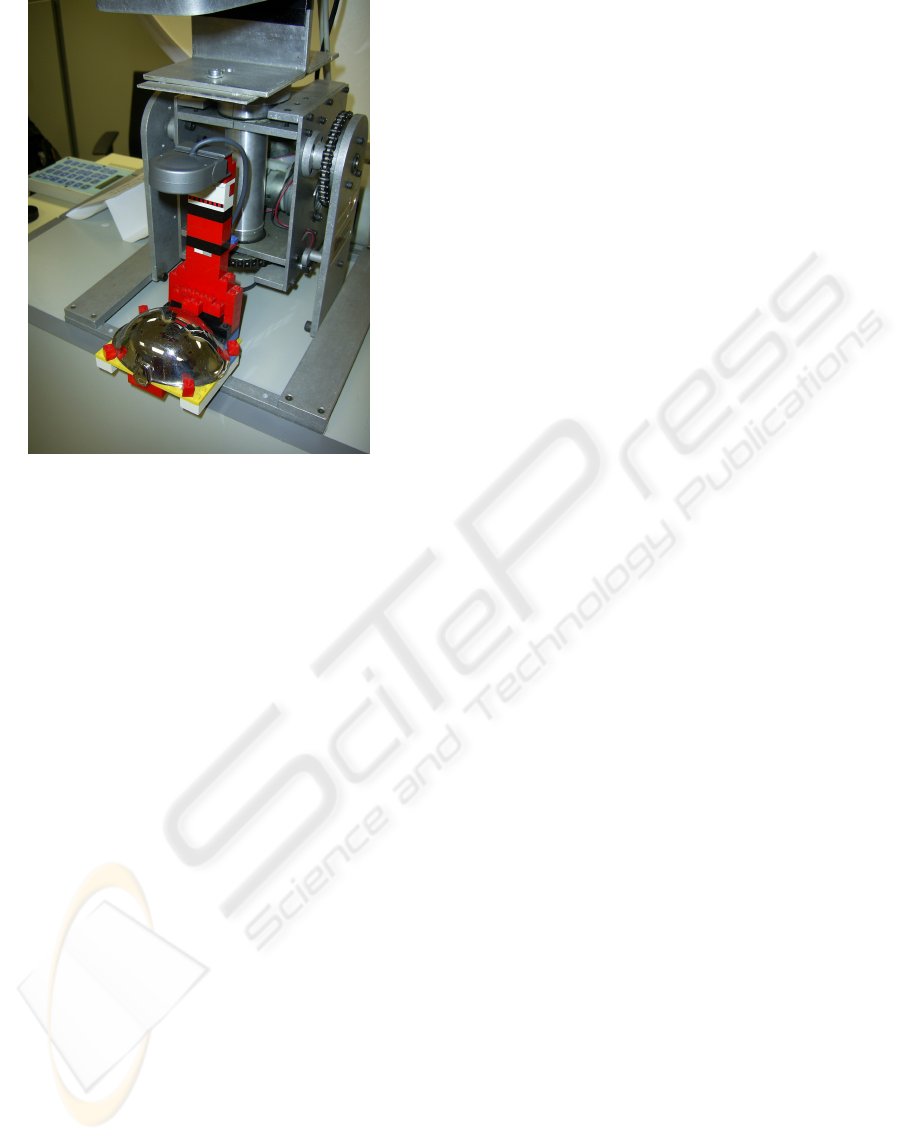
Figure 1: Omnidirectional camera.
as seen from the position of the camera.
A background model is obtained as the mean
value of a number of frames taken when no person
is present in the room. After that, the subtracted in-
put images are thresholded and the close operator is
applied. From the obtained image, connected compo-
nents are localized and their area is estimated. Also,
for each connected component, the Euclidean dis-
tance from the nearest point of the component to the
center of the ellipse is estimated, as well as the angle
of the center of mass of the component with respect to
the center of the ellipse and its largest axis. Note that,
as we are using an ellipse instead of a circle, the near-
ness measure obtained (the Euclidean distance) is not
constant for a fixed real range to the camera, though it
works well as an approximation. The robot uses this
estimate to keep an appropriate interaction distance.
The background model M is updated with each
input frame:
M(k + 1) = M (k) + U(k) · [I(k) − M (k)] (1)
, where I is the input frame and U is the updating
function:
U(k) = exp(−β · D(k)) (2)
D(k) = α·D(k −1) + (1−α)|I(k) −I(k −1)| (3)
α (between 0 and 1) and β control the adaptation
rate. Note that M , U and D are images, the x and y
variables have been omitted for simplicity. For large
values of α and β the model adaptation is slow. In
that case, new background objects take longer to enter
the model. For small values of α and β, adaptation
is faster, which can make animated objects enter the
model.
The method described up to this point still has a
drawback. Inanimate objects should be considered
background as soon as possible. However, as we are
working at a pixel level, if we set the α and β parame-
ters too low we run the risk of considering static parts
of animate objects as background too. This problem
can be alleviated by processing the image D. For each
foreground blob, its values in D are examined. The
maximum value is found, and all the blob values in D
are set to that level. Let the foreground blobs at time
step k be represented as:
B
i
= {x
ij
, y
ij
} ; i = 1, .., NB ; j = 1, .., N
i
(4)
There are NB blobs, each one with N
i
pixels.
Then, after (3) the following is applied:
m
i
= max
j=1,..,N
i
D(x
ij
, y
ij
, k) ; i = 1, .., NB (5)
D(x
ij
, y
ij
, k) = m
i
; i = 1, .., N B ; j = 1, .., N
i
(6)
With this procedure the blob only enters the back-
ground model when all its pixels remain static. The
blob does not enter the background model if at least
one of its pixels has been changing.
3 FACE DETECTION
Omnidirectional vision allows the robot to detect peo-
ple in the scene, just to make the neck turn towards
them (or somehow focus its attention). When the neck
turns, there is no guarantee that omnidirectional vi-
sion has detected a person, it can be a coat stand,
a wheelchair, etc. A face detection module should
be used to detect people (and possibly facial fea-
tures). Facial detection commonly uses skin-color as
the most important feature. Color can be used to de-
tect skin zones, though there is always the problem
that some objects like furniture appear as skin, pro-
ducing many false positives. Figure 2 shows how this
problem affects detection in the ENCARA facial de-
tector (M. Castrillon-Santana and Hernandez, 2005),
which (besides other additional cues) uses normalized
red and green color components for skin detection.
In order to alleviate this problem, stereo informa-
tion is very useful to discard objects that are far from
USEFUL COMPUTER VISION TECHNIQUES FOR A ROBOTIC HEAD
385
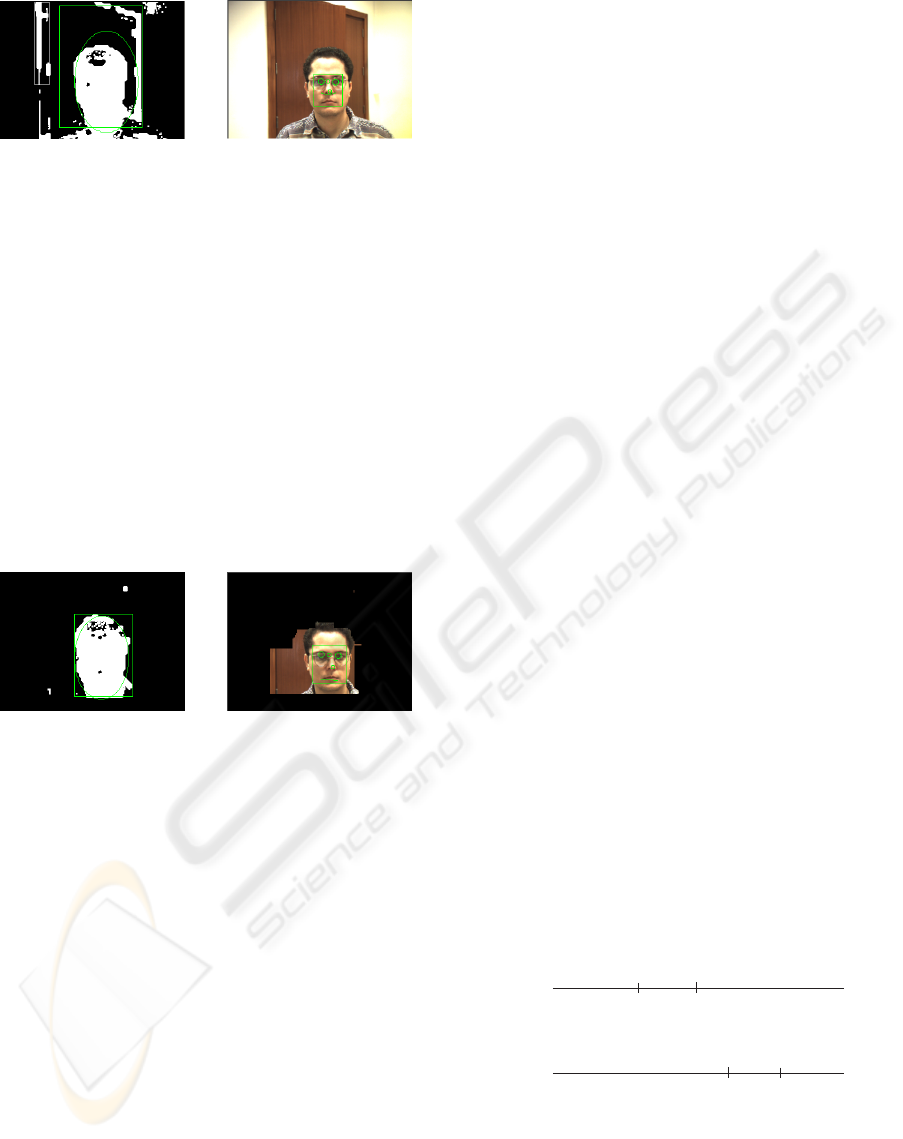
Figure 2: Skin color detection. Note that wooden furniture
is a distractor for facial detection. Both the bounding box
and the best-fit ellipse are rather inaccurate (left).
the robot, i.e. in the background. Stereo cameras are
nowadays becoming cheaper and faster. A depth map
is computed from the pair of images taken by a stereo
camera situated under the nose of the robot. The depth
map is efficiently computed with an included opti-
mized algorithm and library. The map is thresholded
and an AND operation is performed between this map
and the image that the facial detector uses. Fusion of
color and depth was also used in (Darrell et al., 1998;
Moreno et al., 2001; Grange et al., 2002). The results
are shown in Figure 3. Note that most of the undesired
wood colored zones are filtered out.
Figure 3: Skin color detection using depth information.
4 PERSON RECOGNITION
In (Schulte et al., 1999) three characteristics are sug-
gested as critical to the success of robots that must ex-
hibit spontaneous interaction in public settings. One
of them is the fact that the robot should have the
capability to adapt its human interaction parameters
based on the outcome of past interactions so that it
can continue to demonstrate open-ended behaviour.
CASIMIRO is intended to interact with people. Hu-
mans will be the most important ”object” in its en-
vironment. Data associated to humans (gathered
throughout the interaction) should be stored in mem-
ory, so that the robot could take advantage of previ-
ous experiences when interacting with them. Breazeal
(Breazeal, 2002) argues that to establish and maintain
relationships with people, a sociable robot must be
able to identify the people it already knows as well as
add new people to its growing set of known acquain-
tances. In turn, this capacity will be part of the robot’s
autobiographical memory.
In order to make this person memory possible,
gathered data should be unambiguously associated
to the correct person. Facial recognition would be
the perfect approach. However, the experience of
the author with face recognition is somewhat nega-
tive: face recognition still does not work well in un-
restricted scenarios. Recognition rates fall as more
time passes since the training samples were taken. Il-
lumination, pose and expression variations normally
reduce recognition rates dramatically.
Colour histograms of (part of) the person’s body
could also be used as a recognition technique. Colour
histograms are simple to calculate and manage and
they are relatively robust. The price to pay is the lim-
itation that data in memory will make sense for only
one day (at the most). Colour histograms of a person’s
body were used for short-term identification people in
(Maxwell, 2003; Kahn, 1996; Maxwell et al., 1999)
and also for people tracking (Krumm et al., 2000;
Collins and Dennis, 2000).
CASIMIRO achieves person identity maintenance
by using colour histograms in conjunction with a sim-
ple person tracking algorithm. Tracking is done in
1D, for the interesting position is the angle of the per-
son with respect to the robot.
The implemented tracking algorithm is very sim-
ple. Each person is represented as a single point in
two sets of horizontal positions (positions range from
0 to 180) at times t − 1 and t. The association of
points between the two sets is obtained as that which
minimizes the total sum of distances between points
of the two sets. This minimization involves a facto-
rial search, though it is practical for the number of
people that will be expected to interact with the robot.
Ties can appear, for example in the case of crossings,
see the example of Figure 4. These ties are broken
by selecting the association with lowest variance of
distances, 1 with A and 2 with B in the case of the
example. This always selects non-crossings.
0º
1
A
B
2
0º
t-1
t
180º
180º
Figure 4: Tie in sum of distances. The sum of distances
|1 − A| + |2 − B| is equal to |1 − B| + |2 − A|. Without
further information, we can not know if the two individuals
have crossed or not.
Crossings are detected by considering that, in a
crossing, there is always a fusion and a separation of
ICINCO 2007 - International Conference on Informatics in Control, Automation and Robotics
386
person blobs. Person blobs are detected by the om-
nidirectional vision system (see above). Fusions and
separations are detected as follows:
• A blob fusion is detected when the number of
blobs in the whole omnidirectional image de-
creases by one at the same time that one of the
blobs increases its area significantly.
• A blob separation is detected when the number of
blobs in the image increases by one at the same
time that a fusioned blob decreases its area signif-
icantly.
The only way to know if a there is a crossing is
by maintaining some sort of description of the blobs
before and after the fusion. Histograms of U and V
colour components are maintained for each blob. The
Y component accounts for luminance and therefore
it was not used. Whenever a separation is detected,
the histograms of the left and right separated blobs
are compared with those of the left and right blobs
that were fusioned previously. Intersection (Swain
and Ballard, 1991) was used to compare histograms
(which must be normalized for blob size). This proce-
dure allows to detect if there is a crossing, see Figure
5. The histogram similarities calculated are shown
in Figure 6. A crossing is detected if and only if
(b + c) > (a + d). Note that in the comparison no
threshold is needed, making crossing detection rela-
tively robust.
0º
0º
0º
t-2
t-1
(fusion)
(separation)
t
180º
180º
180º
Figure 5: Crossings can be detected by comparing blob his-
tograms at fusion and separation events.
(blobs right before fusion)
a
c
d
b
(blobs right after separation)
Figure 6: Blob similarities calculated.
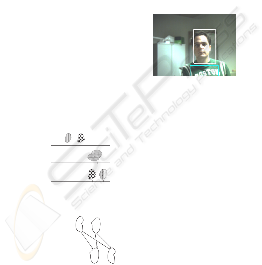
In order to achieve person identification, a set of
Y-U histograms are stored for each person detected.
The zone from which these histograms are calculated
is a rectangle in the lower part of the image taken
from the stereo camera placed under the nose of the
robot. The rectangle is horizontally aligned with the
centre of the face rectangle detected, and extends to
the lower limit of the image (chest and abdomen of
standing people will always occupy that lower part of
the image). The upper edge of the rectangle is always
under the lower edge of the face rectangle detected.
The width of the rectangle is proportional to the width
of the face rectangle detected.
Figure 7: Region used for person identification.
When the robot fixates on a person that the track-
ing system has labelled as new (the tracking system
detects a new person in the scene when the number
of foreground blobs increases and no blob separation
is detected), it compares the histograms of the fixated
individual with those of previously met individuals.
This search either gives the identity of a previously
seen individual or states that a new individual is in
the scene. In any case the set of stored histograms for
the individual is created/updated.
5 HEAD NOD/SHAKE
DETECTION
Due to the fact that practical (hands-free) voice recog-
nition is very difficult to achieve for a robot, we de-
cided to turn our attention to simpler (though use-
ful) input techniques such as head gestures. Head
nods and shakes are very simple in the sense that
they only provide yes/no, understanding/disbelief, ap-
proval/disapproval meanings. However, their impor-
tance must not be underestimated because of the fol-
lowing reasons: the meaning of head nods and shakes
is almost universal, they can be detected in a relatively
simple and robust way and they can be used as the
minimum feedback for learning new capabilities.
The system for nod/shake detection described in
(Kapoor and Picard, 2001) achieves a recognition ac-
USEFUL COMPUTER VISION TECHNIQUES FOR A ROBOTIC HEAD
387
curacy of 78.46%, in real-time. However, the system
uses complex hardware and software. An infrared
sensitive camera synchronized with infrared LEDs is
used to track pupils, and a HMM based pattern an-
alyzer is used to the detect nods and shakes. The
system had problems with people wearing glasses,
and could have problems with earrings too. The
same pupil-detection technique was used in (Davis
and Vaks, 2001). That work emphasized the im-
portance of the timing and periodicity of head nods
and shakes. However, in our view that information
is not robust enough to be used. In natural human-
human interaction, head nods and shakes are some-
times very subtle. We have no problem in recognizing
them because the question has been clear, and only the
YES/NO answers are possible. In many cases, there
is no periodicity at all, only a slight head motion. Of
course, the motion could be simply a ’Look up’/’Look
down’/’Look left’/’Look right’, though it is not likely
after the question has been made.
For our purposes, the nod/shake detector should
be as fast as possible. On the other hand, we assume
that the nod/shake input will be used only after the
robot has asked something. Thus, the detector can
produce nod/shake detections at other times, as long
as it outputs right decisions when they are needed.
The major problem of observing the evolution of sim-
ple characteristics like intereye position or the rectan-
gle that fits the skin-color blob is noise. Due to the
unavoidable noise, a horizontal motion (the NO) does
not produce a pure horizontal displacement of the ob-
served characteristic, because it is not being tracked.
Even if it was tracked, it could drift due to lighting
changes or other reasons. In practice, a horizontal
motion produces a certain vertical displacement in the
observed characteristic. This, given the fact that deci-
sion thresholds are set very low, can lead the system to
error. The performance can be even worse if there is
egomotion, like in our case (camera placed on a head
with pan-tilt).
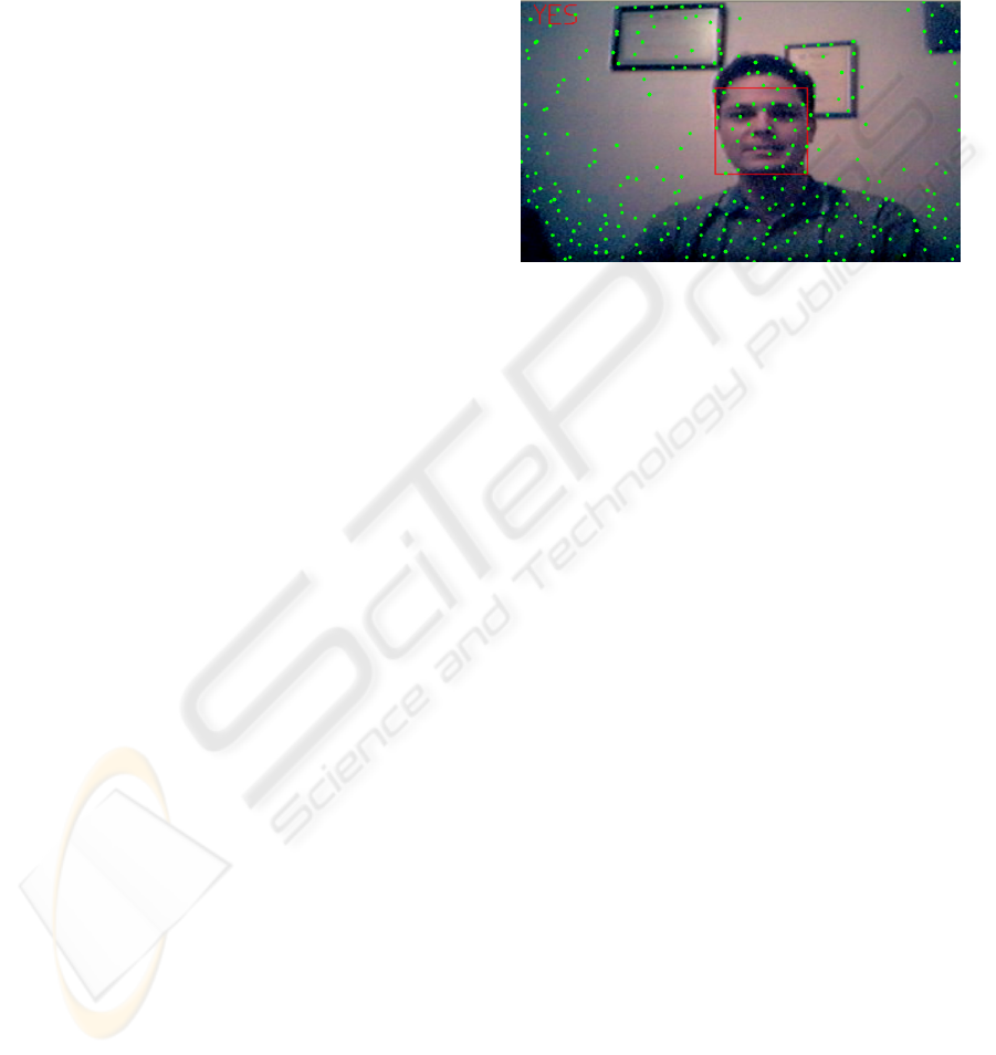
The proposed algorithm uses the pyramidal
Lucas-Kanade tracking algorithm described in
(Bouguet, 1999). In this case, there is tracking, and
not of just one, but multiple characteristics, which
increases the robustness of the system. The tracker
looks first for a number of good points to track over
the whole image, automatically. Those points are
accentuated corners. From those points chosen by
the tracker we attend only to those falling inside the
rectangle that fits the skin-color blob, observing their
evolution. Note that even with the LK tracker there
is noise in many of the tracking points. Even in an
apparently static scene there is a small motion in
them.
The method is shown working in Figure 8. The
LK tracker allows to indirectly control the number of
tracking points. The larger the number of tracking
points, the more robust (and slow) the system. The
method was tested giving a recognition rate of 100%
(73 out of 73, questions with alternate YES/NO re-
sponses, using the first response given by the system).
Figure 8: Head nod/shake detector.
What happens if there are small camera displace-
ments? In order to see the effect of this, linear cam-
era displacements were simulated in the tests. In
each frame, an error is added to the position of all
the tracking points. If (D
x
, D
y
) is the average dis-
placement of the points inside the skin-color rectan-
gle, then the new displacement is D
x
+e
x
and D
y
+e
y
.
The error, which is random and different for each
frame, is bounded by −e
max
< e
x
< e
max
and
−e
max
< e
y
< e
max
. Note that in principle it is
not possible to use a fixed threshold because the er-
ror is unknown. The error also affects to the track-
ing points that fall outside the rectangle. Assuming
that the objects that fall outside the rectangle are static
we can eliminate the error and keep on using a fixed
threshold, for (D
x
+ e
x
) − (F
x
+ e
x
) ≈ D
x
and
(D
y
+ e
y
) − (F
y
+ e
y
) ≈ D
y
. For the system to work
well it is needed that the face occupies a large part of
the image. A zoom lens should be used. When a sim-
ulated error of e
max
= 10 pixels was introduced, the
recognition rate was 95.9% (70 out of 73). In this case
there is a slight error due to the fact that the compo-
nents F
x
and F
y
are not exactly zero even if the scene
outside the rectangle is static.
Another type of error that can appear when the
camera is mounted on a mobile device like a pan-
tilt unit is the horizontal axis inclination. In practice,
this situation is common, especially with small incli-
nations. Inclinations can be a problem for deciding
between a YES and a NO. In order to test this effect,
an inclination error was simulated in the tests (with
the correction of egomotion active). The error is a ro-
tation of the displacement vectors D a certain angle α
ICINCO 2007 - International Conference on Informatics in Control, Automation and Robotics
388

clockwise. Recognition rates were measured for dif-
ferent values of α, producing useful rates for small
inclinations: 90% (60 out of 66) for α = 20, 83.8%
(57 out of 68) for α = 40 and 9.5% (6 out of 63) for
α = 50.
6 CONCLUSIONS
four simple but useful computer vision techniques
have been described, suitable for human-robot in-
teraction. First, an omnidirectional camera setting
is described that can detect people in the surround-
ings of the robot, giving their angular positions and
a rough estimate of the distance. The device can
be easily built with inexpensive components. Sec-
ond, we comment on a color-based face detection
technique that can alleviate skin-color false positives.
Third, a simple head nod and shake detector is de-
scribed, suitable for detecting affirmative/negative,
approval/disapproval, understanding/disbelief head
gestures. The four techniques have been implemented
and tested on a prototype social robot.
ACKNOWLEDGEMENTS
This work was partially funded by research projects
UNI2005/18 of Universidad de Las Palmas de Gran
Canaria and the Spanish Ministry for Education and
Science and FEDER (TIN2004-07087).
REFERENCES
Bouguet, J. (1999). Pyramidal implementation of the Lucas
Kanade feature tracker. Technical report, Intel Corpo-
ration, Microprocessor Research Labs, OpenCV doc-
uments.
Breazeal, C. L. (2002). Designing social robots. MIT Press,
Cambridge, MA.
Collins, G. and Dennis, L. A. (2000). System description:
Embedding verification into microsoft excel. In Con-
ference on Automated Deduction, pages 497–501.
Darrell, T., Gordon, G., Harville, M., and Woodfill, J.
(1998). Integrated person tracking using stereo, color,
and pattern detection. In Procs. of IEEE Computer
Society Conference on Computer Vision and Pattern
Recognition, pages 601–608, Santa Barbara, CA.
Davis, J. and Vaks, S. (2001). A perceptual user interface
for recognizing head gesture acknowledgements. In
Proc. of ACM Workshop on Perceptual User Inter-
faces, Orlando, Florida.
Deniz, O. (2006). An Engineering Approach to Sociable
Robots. PhD thesis, Department of Computer Science,
Universidad de Las Palmas de Gran Canaria.
Fong, T., Nourbakhsh, I., and Dautenhahn, K. (2003). A
survey of socially interactive robots. Robotics and Au-
tonomous Systems, 42(3-4).
Grange, S., Casanova, E., Fong, T., and Baur, C. (2002).
Vision based sensor fusion for human-computer inter-
action. In Procs. of IEEE/RSJ International Confer-
ence on Intelligent Robots and Systems. Lausanne,
Switzerland.
Kahn, R. (1996). Perseus: An Extensible Vision System for
Human-Machine Interaction. PhD thesis, University
of Chicago.
Kapoor, A. and Picard, R. (2001). A real-time head nod and
shake detector. In Proceedings from the Workshop on
Perspective User Interfaces.
Krumm, J., Harris, S., Meyers, B., Brumitt, B., Hale, M.,
and Shafer, S. (2000). Multi-camera multi-person
tracking for easyliving. In 3rd IEEE International
Workshop on Visual Surveillance, Dublin, Ireland.
M. Castrillon-Santana, H. Kruppa, C. G. and Hernandez, M.
(2005). Towards real-time multiresolution face/head
detection. Revista Iberoamericana de Inteligencia Ar-
tificial, 9(27):63–72.
Maxwell, B. (2003). A real-time vision module for interac-
tive perceptual agents. Machine Vision and Applica-
tions, (14):72–82.
Maxwell, B., Meeden, L., Addo, N., Brown, L., Dickson, P.,
Ng, J., Olshfski, S., Silk, E., and Wales, J. (1999). Al-
fred: the robot waiter who remembers you. In Procs.
of AAAI Workshop on Robotics.
Moreno, F., Andrade-Cetto, J., and Sanfeliu, A. (2001). Lo-
calization of human faces fusing color segmentation
and depth from stereo. In Procs. ETFA, pages 527–
534.
Schulte, J., Rosenberg, C., and Thrun, S. (1999). Spon-
taneous short-term interaction with mobile robots in
public places. In Procs. of the IEEE Int. Conference
on Robotics and Automation.
Swain, M. and Ballard, D. (1991). Color indexing. Int.
Journal on Computer Vision, 7(1):11–32.
USEFUL COMPUTER VISION TECHNIQUES FOR A ROBOTIC HEAD
389
