
DIRECTIONAL MANIPULABILITY FOR MOTION
COORDINATION OF AN ASSISTIVE MOBILE ARM
K. Nait-Chabane, P. Hoppenot and E. Colle
IBISC Université d’Evry Val d’Essonne, 40 rue de plevoux 91020, Evry, France
Keywords: Mobile manipulator, manipulability, redundancy systems, robotic assistance.
Abstract: In this paper, we address the problem of coordinated motion control of a manipulator arm embarked on a
mobile platform. The mobile manipulator is used for providing assistance for disabled people. In order to
perform a given task by using mobile manipulator redundancy, we propose a new manipulability measure
that incorporates both arm manipulation capacities and the end-effector imposed task. This measure is used
in a numerical algorithm to solve system redundancy and then compared with other existing measures.
Simulation and real results show the benefit and efficiency of this measure in the field of motion
coordination.
1 INTRODUCTION
In assistive robotics, a manipulator arm constitutes
one possible solution for restoring some
manipulation functions to victims of upper limb
disabilities. The literature proposes three distinct
manipulator arm configurations. The first one
consists of a workstation in which a manipulator arm
evolves within a structured environment (RAID,
AFMASTER (Busnel, 2001)). In the second
configuration, a manipulator arm is added to an
electrical wheelchair ((Kwee, 1993), (Evers, 2001)).
The third configuration aims at expanding the field
of application of manipulator arm by making it
mobile, MoVAR (Van der Loos, 1995
), URMAD-
MOVAID (Dario, 1999) and ARPH (Hoppenot,
2002), that offers many advantages. Our research
deals with this third configuration. Such a system
possesses more degrees of freedom than necessary
for task execution. Any given point in the workspace
may be reached by moving the manipulator arm or
moving the mobile platform or by a combination of
both. To facilitate the use of the system by the
handicapped person, the idea is that the operator
pilots the gripper and that the remainder of the
articulated system follows. We have focused
attention on the use of redundancy for controlling a
mobile arm.
Manipulability measures play an important role
in
the design, analysis, evaluation and optimization
in manipulation robotics; it is a scalar that quantifies
how well the system behaves with respect to force
and motion transmission. These measures however
do not include information either on the task
imposed or on the direction of end-effector motion.
We propose an additional measure that takes the task
to be performed into account.
This paper is organized as follows. Section 2
prese
nts the work conducted towards devising
different solutions to the redundancy problem.
Section 3 discusses the mobile arm and its kinematic
models before Section 4 introduces the
manipulability concept and primary set of related
measures used in the literature on robotics. Section 5
then lays out a new measure that takes both the
system manipulation capacities and task in progress
into account. We will recall the principle behind the
kinematic control scheme used to solve redundancy
problems in Section 6, followed by an illustration of
the benefit of our new measure by means of
simulation and real results (in Section 7).
2 RELATED RESEARCH WORK
A considerable amount of interest has been shown
over the past few years in mobile manipulators.
Seraji (Seraji, 1993) presents a simple online
approach for the motion control of mobile
manipulators using augmented Jacobian matrices.
This kinematic approach requires additional
constraints to be satisfied for the manipulator
configuration. The approach proposed may be
201
Nait-Chabane K., Hoppenot P. and Colle E. (2007).
DIRECTIONAL MANIPULABILITY FOR MOTION COORDINATION OF AN ASSISTIVE MOBILE ARM.
In Proceedings of the Fourth International Conference on Informatics in Control, Automation and Robotics, pages 201-208
DOI: 10.5220/0001642402010208
Copyright
c
SciTePress
applied with equal ease to both nonholonomic and
holonomic mobile robots. Yamamoto and Yun
(Yamamoto, 1987) set out to decompose the motion
of the mobile manipulator into two subsystems
based on the concept of preferred operating region.
The mobile platform is controlled so as to bring the
manipulator into a preferred operating
region/configuration, with respect to the mobile
platform, as the manipulator performs a variety of
unknown manipulation tasks. The authors used the
manipulability measure of the manipulator arm to
define this preferred operating region. The principal
advantage of this approach lies in its decentralized
planning and control of the mobile platform and
manipulator arm. However, the case when the
manipulator is mounted at the center of the axis
between the two driving wheels lies at a singularity
in the method proposed by Yamamoto and Yun
(Yamamoto, 1987). Nagatani (Nagatani, 2002)
developed an approach to plan mobile base's path
which satisfies manipulator's manipulability. The
controllers used for manipulation and locomotion
differ from one another.
Khatib (Khatib, 1995) Khatib [10] proposed to
use a joint limit constraint in mobile manipulation in
the form of potential function while his approach is
to use the inherent dynamics characteristics of
mobile manipulator in operational space.
Additionally, he analyzed the inertial properties of a
redundant arm with macro-micro structure.
Kang (Kang, 2001) derived a combined potential
function algorithm to determine a posture satisfying
both the reduced inertia and joint limit constraints
for a mobile manipulator. The author then integrated
the inertia property algorithm into a damping
controller in order to reduce the impulse force upon
collision as well as to regulate contact.
Yoshikawa (Yoshikawa, 1990) introduced the
arm manipulators manipulability and used it to solve
the redundancy of such systems. The manipulability
of mobile manipulator has been studied by few
authors. Yamamoto and Yun (Yamamoto, 1999)
have treated both locomotion and manipulation
within the same framework from a task space
perspective. They have presented the kinematic and
dynamic contributions to manipulators and platforms
by means of the so-called task space ellipsoid.
Bayle (Bayle, 2001) extended the definition of
manipulability to the case of a mobile manipulator
and then applied it in an inversion process for
solving redundancy.
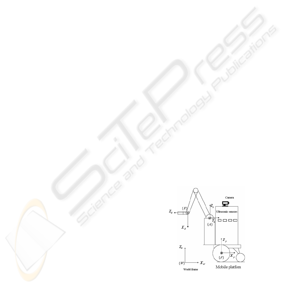
3 DESCRIPTION OF
ROBOTIZED ASSISTANT
The mobile manipulator consists of a Manus arm
mounted on a mobile platform powered by two
independent drive wheels. Let's start by defining a
fixed world reference frame {W}, a moving
platform frame {P} attached to the midway between
the two drive wheels, a moving arm frame {A}
related to the manipulator base, and a moving end-
effector frame {E} attached to the arm end-effector
(see Fig. 1).
We will adopt the following assumptions in
modeling the mobile manipulator system: no
slipping between wheel and floor; a platform
incapable of moving sideways in order to maintain
the nonholonomic constraint; and a manipulator
rigidly mounted onto the platform.
The forward kinematics of a serial chain manipulator
relating joint space and task space variables is
expressed by:
()
aaa
X
fq
=
(1)
where
12
[, , ]
T
aaa am
m
X
xx x R=" ∈
n
∈
a
is the vector of
task variables in an m-dimensional task space,
is the vector of joint
variables in n-dimensional variables (called the
generalized coordinates), and f
12
[, , ]
T
aaa an
qqq q R="
a
is the nonlinear
function of the forward kinematic mapping
()
aaa
X
Jqq=
(2)
where
a
X
is the task velocity vector, the joint
velocity vector and
a
q
()
aa
J
q
the Jacobian matrix.
Figure 1: Mobile manipulator system.
For the kinematic modeling of the considered
manipulator arm, we make use of Denavit-
Hartenberg parameters (Sciavicco, 1996). Manus
arm possesses six rotoid joints, with 3 DOF for
ICINCO 2007 - International Conference on Informatics in Control, Automation and Robotics
202

gripper positioning and 3 DOF for gripper
orientation. The Cartesian coordinates of the end-
effector relative to the arm base frame {A} are given
by:
1433212
2433212
34332
4
5
6
()-
()
a
a
a
a
a
a
a
1
1
x
Lc Lc c Ls
x
Lc Lc s Lc
xLsLs
X
x
x
x
φ
θ
ψ
=+
⎧
⎪
=+ +
⎪
⎪
=+
⎪
=
⎨
=
⎪
⎪
=
⎪
=
⎪
⎩
(3)
where
cos( ),
iai
cq= sin( )
iai
s
q
=
and
represent the length of shoulder, upper arm and
lower arm, respectively.
234
,,LLL
123
[, , ]
T
aa a
xxx
and
[,, ]
T
φ
θψ
represent the Cartesian
coordinates and Euler angles of the end-effector,
respectively. In this paper, we will only consider the
three main joints of the arm, as given by the
generalized vector
123
[, , ]
T
aaaa
qqqq= .
The platform location is given by three
operational coordinates
,
pp
x
y
and
p
θ
, which
define its position and orientation. The generalized
coordinate vector is thus: and the
generalized velocity vector is:
[,,]
T
pppp
qxyθ=
[, , ]
pppp
qxy
θ
=
.
The constraint equation applied to the platform
has the following form:
() 0
pp
Aq q
=
(4)
in which
()[sin() cos()0]
pp p
Aq
θ
θ
=−
.
The kinematic model of the mobile platform is
given in (Campion, 1996):
()
pp
qSqu=
P
⎥
⎥
(5)
where
and u
cos( ) 0
() sin()0
01
p
pp
Sq
θ
θ
⎡⎤
⎢
=
⎢
⎢⎥
⎣⎦
p
= [v,ω]
T
, with v
and
ω being the linear and angular velocities of the
platform, respectively.
The forward kinematic model of the mobile
manipulator may be expressed in the following
form:
(, )
pa
X
fq q=
(6)
where is the generalized coordinates of the
mobile platform and the joint variables of the
arm, as defined above.
p
q
a
q
The configuration of the mobile manipulator is
therefore defined by the
N generalized coordinates
(N=n+3):
1
[,] [, ,, ,, ]
TTT T
pa p ppa an
qqq xy q qθ== "
(7)
The direct kinematic model for the positioning
task of the considered mobile arm relative to world
frame
{W} is given by:
12 6
[, , , ] (, )
T
ap
X
xx x fqq=="
(8)
12 1
22 1
33
44
55
66
()c()s
()s()c
22
pp
pp
pa a
pa a
a
ap p
a
a
xx x a bx
xy xa bx
xxc
X
xx
xx
xx
θθ
θθ
ππ
θφθ
θ
ψ
=+ + −−
=+ + +−
=+
=
=+−=+−
==
==
⎧
⎪
⎪
⎪
⎪
⎨
⎪
⎪
⎪
⎪
⎩
(9)
where
cos( ),
P
P
c
θ
θ
=
sin( )
P
P
s
θ
θ
=
; a, b and c are
the Cartesian coordinates of the manipulator arm
base with respect to the mobile platform frame {P}.
The instantaneous kinematic model is then given
by:
()
X
Jqq=
(10)
with:
()
f
Jq
q
∂
=
∂
.
We can observe that generalized velocities are
dependent; they are linked by the nonholonomic
constraint. The platform constraint described by (4)
can be written in the following form:
q
[( )0] 0
p
Aq q=
(11)
According to (5), the relation between the
generalized velocity vector of the system and its
control velocities can be written as follows:
()qMqu
=
(12)
DIRECTIONAL MANIPULABILITY FOR MOTION COORDINATION OF AN ASSISTIVE MOBILE ARM
203
where
()0
() .
0
pp
n
Sq
Mq
I
⎡⎤
=
⎢⎥
⎣⎦
I
n
is an n-order identity matrix and
1
[, , , , ].
T
aan
uvwq q=
"
The instantaneous kinematic model does not
include the nonholonomic constraint of the platform
given by (11). The relationship between the
operational velocities of the mobile manipulator and
its control velocities takes the nonholonomic
platform constraint into account and may be
expressed by the reduced direct instantaneous
kinematic model, i.e.:
()
X
Jqu=
(13)
with:
() () ().
J
qJqMq=
4 MANIPULABILITY MEASURES
A well-established tool used for the motion analysis
of manipulators is known as the manipulability
ellipsoid approach. The concept of manipulability
was originally introduced by Yoshikawa
((Yoshikawa, 1985), (Yoshikawa, 1990)) for arm
manipulators, in order to denote a measure for the
ability of a manipulator to move in certain
directions. The set of all end-effector velocities that
may be attained by joint velocities such that the
Euclidean norm of ,
a
q
22 21/
12
(
aaa an
qqq q=++
"
2
)
,
satisfying
1
a
q ≤
is an ellipsoid in m-dimensional
Euclidean space. This ellipsoid represents the
manipulation capability and is called the
"manipulability ellipsoid".
Yoshikawa defines the manipulability measure w
as follows:
det(() ())
T
aaa a
wJqJq=
(14)
which can be simplified into
det( ( ))
aa
wJq=
when
J
a
(q
a
) is a square matrix.
Let's now consider the singular value
decomposition of
J
a
, as given by:
T
aaa
a
J
UV=∑
(15)
where and are orthogonal
matrices, and:
mm
a
UR
×
∈
nn
a
VR
×
∈
1
2
0
.0
.
0
a
a
mn
a
am
R
σ
σ
σ
×
⎡⎤
⎢⎥
⎢⎥
⎢⎥
Σ= ∈
⎢⎥
⎢⎥
⎢⎥
⎣⎦
#
#
#
#
#
(16)
in which:
12
.
aa am
σ
σσ
≥≥≥"
The value of
12
..
aa am
w
σ
σσ
=
"
is proportional
to the ellipsoid volume.
Another measure has been proposed for
characterizing the distance of a configuration from a
singularity (Salisbury, 1982). This measure is given
by:
2
1
am
a
w
σ
σ
=
(17)
where
1
a
σ
and
m
a
σ
are the maximum and minimum
singular values of the Jacobian matrix, respectively.
Bayle (Bayle, 2001) defined a measure w
5
that
extended the notion of eccentricity of the
ellipse, i.e.:
2
5
2
1
1.
am
a
w
σ
σ
=−
(18)
The structure of the manipulator arm consists of an
arm portion with three joints and a wrist portion with
three joints whose axes intersect at a single point.
The arm portion concerns the positioning task, while
the wrist portion focuses on gripper orientation. It
proves quite useful to divide this study into wrist and
arm singularities. We present herein the
manipulability of the considered system for
positioning tasks.
5 DIRECTIONAL MEASURE
All of the abovementioned measures describe
system manipulability in general terms, without
taking the task the manipulator is being asked to
perform into account. One key factor behind the
failure of these measures is the fact that they do not
include information either on the task or on the
direction the end-effector is required to move. A
new measure should therefore be introduced to
address this situation.
ICINCO 2007 - International Conference on Informatics in Control, Automation and Robotics
204
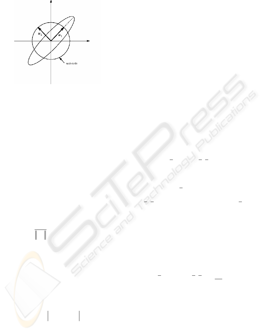
Figure 2: Manipulability ellipse in the two-dimensional
case.
The Singular Value Decomposition (15) of the
Jacobian matrix and its geometric relationship offer
further insights into characterizing the
manipulability of mechanical systems. Let
u
ai
be the
i
th
column vector of U
a
. The primary axes of the
manipulability ellipsoid are then:
11 2 2
,,
a a a a am am
uu u
σ
σσ
"
. Figure 2 provides an
illustration of the two-dimensional case, according
to which
u
1
and u
2
yield the major and minor ellipse
axes, respectively. We propose to include
information on the direction of the task wished to
precisely know the manipulation capacity of the arm
manipulator for the execution of this operational
task.
Let
d
X
be the desired task. We now define a
unit vector
d
d
X
d
X
=
, which gives the direction of
the imposed task.
By using properties of the scalar product and the
singular values that represent radius of the ellipsoid,
we define a new manipulability measure as being the
sum of the absolute values of the scalar products of
the directional vector of the task by the singular
vectors pondered by their corresponding singular
values. This new measure is noted w
dir
.
1
(.)
m
T
dir ai ai
i
wdu
σ
=
=
∑
(19)
This measure is maximized when the arm capacity
of manipulation according to the direction of the
task imposed is maximal. It is equal to zero if there
is no possibility of displacement according to this
direction.
6 CONTROL SCHEME
Whitney (Whitney, 1969) first proposed using the
pseudo-inverse of the manipulator Jacobian in order
to determine the minimum norm solution for the
joint rates of a serial chain manipulator capable of
yielding a desired end-effector velocity. A weighted
pseudo-inverse solution approach also allows
incorporating the various capabilities of different
joints, as discussed in Nakamura (Nakamura, 1991)
and Yoshikawa (Yoshikawa, 1984). One variant of
this approach includes superposition of the Jacobian
null space component on the minimum norm
solution to optimize a secondary objective
function (Baerlocher, 2001).
This same notion can then be extended to the
case of a nonholonomic mobile manipulator. The
inverse of the system given by equation (12) exhibits
the following form:
()
d
uJX IJJZ
++
=+−
(20)
where Z is a (N-1)-dimensional arbitrary vector.
The solution to this system is composed of both a
specific solution
d
J
X
+
that minimizes control
velocities norm and a homogeneous solution
(IJJZ
+
− )
belonging to the null space
()NJ
. By
definition, these latter added components do not
affect task satisfaction and may be used for other
purposes. For this reason, the null space is
sometimes called the redundant space in robotics.
The Z vector can be utilized to locally minimize
a scalar criterion. Along the same lines,
Bayle (Bayle,2001b) proposed the following
scheme:
()(
TT
d
P
uJX WIJJM
q
++
∂
=−−
∂
)
(21)
where
d
X
is the desired task vector, W a positive
weighting matrix, and P(q) the objective function
dependent upon manipulator arm configuration. To
compare the advantage of our manipulability
measure with those presented in the literature, the
control scheme whose objective function depends on
various measures (
w, w
5
and w
d
) is to be applied.
For manipulation tasks involving a manipulator arm,
it is helpful to consider manipulability functions
DIRECTIONAL MANIPULABILITY FOR MOTION COORDINATION OF AN ASSISTIVE MOBILE ARM
205
whose minima correspond to optimal configurations,
e.g. (-w), (-w
d
) or w
5
.
As for the calculus, we used the numerical
gradient of P(q).
7 RESULTS
7.1 Simulation Results
In this section, we will consider a Manus arm
mounted on a nonholonomic mobile platform
powered by two independent-drive wheels, as
described in Section 3. The mobile platform is
initially directed toward the positive X-axis at rest
(q
p
=[0, 0, 0]
T
) and the initial configuration of the
manipulator arm is: q
a
= [4.71, 2.35, 4.19]
T
(rad).
The arm is fixed on the rear part of the platform. The
coordinates of the arm base with respect to the
platform frame are: [-0.12, -0.12, 0.4]
T
(m). The
imposed task consists of following a straight line
along a Y-axis of the world frame {W}. The velocity
along a path is constant and equal to 0.05 m.s
-1
.
Results obtained in the following cases have been
reported:
in optimizing arm manipulability measure w;
in optimizing arm manipulability measure w
dir
.
The comparison criteria are thus:
Platform trajectory profile,
indicator of energy spent E by the platform,
manipulation capacity of the arm at the end of
the task, measured by w.
w is the most widely used indicator of
manipulability found in the literature. In our case, w
serves as a reference to evaluate the efficiency of the
control algorithm in terms of arm manipulability; its
values range between 0, which corresponds to
singular configurations, and 0.06, which corresponds
to good manipulability. In addition, we are looking
for forward displacements of the platform and
smooth trajectories. End-effector trajectories enable
checking if the task has been performed adequately.
E is defined by
2
lr
2
E
vv=+
∑
, with v
l
and v
r
the
linear velocities respectively of the left and right
wheels of the platform.
Before presenting each case separately, it should
be noted that, for each one of them, the task is
carried out correctly.
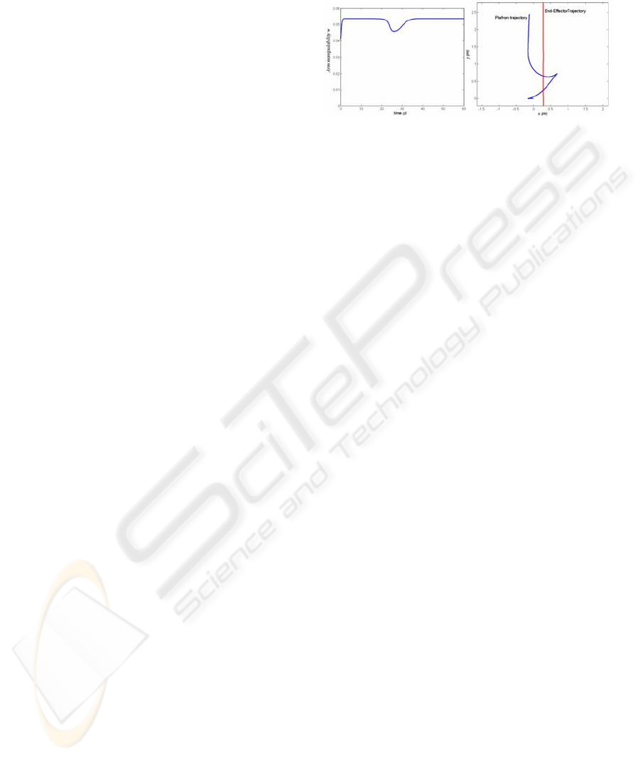
Figure 3 shows simulation results in which arm
manipulability w is used as the optimizing criterion
for solving mobile arm redundancy. As depicted in
Figure 3a, the arm manipulability w quickly
improves up to a threshold corresponding to
acceptable configurations. Around 25 seconds, local
degradation of the manipulability measure is shown
to be quite low.
(a) (b)
Figure 3: Simulation result when optimizing arm
manipulability measure w.
To quickly improve arm manipulability while
performing the imposed task, the arm extends and
the platform retracts (see Fig. 3b). The platform
stops retracting once arm manipulability has been
optimized; afterwards, it advances so that the unit
carries out the imposed task. This evolution
corresponds to the first graining of the platform
trajectory. Since the platform is poorly oriented with
respect to the task direction, its contribution is
limited by the nonholonomic constraint, which does
cause slight degradation to the manipulability, as
shown in Figure 3a. The reorientation of the
platform, which corresponds to the second point of
graining, allows for improvement and optimization
of the manipulability measure. The mobile arm
achieves the desired task with an acceptable arm
configuration from a manipulation perspective; the
platform moves in reverse gear however, which
counters our intended aim. As there are two graining
points, the platform trajectory is not smooth. The
energy indicator E for this trajectory is E=7.15 m
2
s
-2
.
In Figure 4, we have used the proposed
directional manipulability of the arm to solve mobile
arm redundancy. Figure 4a shows the evolution of
the directional manipulability measure w
dir,
and arm
manipulability
w for comparison. The directional
manipulability of the arm is initially good; it
decreases slightly then improves progressively.
Corresponding measure w does not reach its
maximum value, but remains in a beach of
acceptable values, far from the singular
configurations. In this case, no local degradation of
the manipulability measure is detected. Figure 4b
presents the trajectory of the middle axis point on
the platform. This figure indicates that the mobile
platform retracts during a short period of time at the
very beginning in order to improve arm
manipulability. The platform reorients itself
according to the imposed task without changing its
motion direction. In executing a desired task, the
platform thus follows a smoother trajectory and
ICINCO 2007 - International Conference on Informatics in Control, Automation and Robotics
206
displays forward displacements. The energy
indicator E for this trajectory is E=3.1 m
2
.s
-2
. Energy
expenditure is lower than the preceding case.
(a) (b)
Figure 4: Simulation result when optimizing arm
directional manipulability measure w
dir.
7.2 Results on Real System
To illustrate the results presented in theory, we
implemented on the real robot the algorithm.
Starting from a given configuration q
i
, collected by
the sensors data, we impose an operational task on
the end effector of the arm manipulator which
consists in following a straight line according to the
direction perpendicular to the axis longitudinal of
the platform (Y axis of the world frame). Imposed
velocity is 0.005 m per 60 ms cycle.
It should be noted that for each case, the task is
carried out correctly with good configuration from
manipulability point of view.
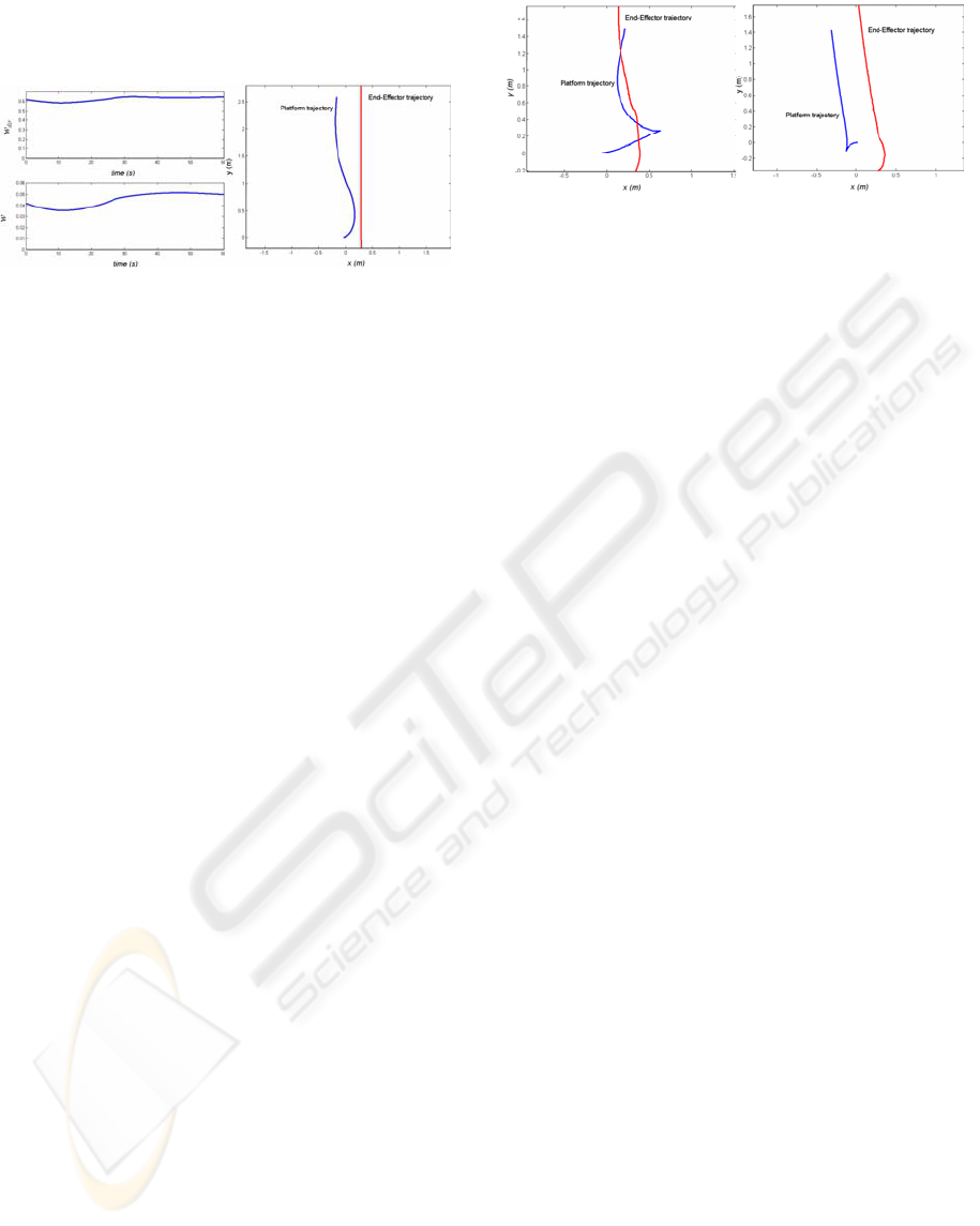
Figure 5 presents the platform and end effector
trajectories respectively in the cases of optimizing
arm manipulability w (figure 5a) and arm directional
manipulability w
dir
(figure 5b).
Platform and OT trajectories presented on Figure 5a
show that the platform carries out most part of its
movement in reverse gear. The end effector follows
a straight line with an error which reaches 21 cm in
end of the task. This error includes a set of
measurement errors and the tracking error.
In the case of directional manipulability
optimization, figure 5b indicates that the platform
moves back a little at the beginning and moves
according to the direction of the task. End-effector
follows a straight line with a weak error at the
beginning (less than 3cm) better than the case of the
optimization of w. The tracking error increases at the
end of the execution of the task. Indeed, as the
calculation of the gripper position is done on the
basis of odometric data, which generates not limited
errors, the tracking error increases.
(a) (b)
Figure 5: End-Effector and platform trajectories in the real
case.
7.3 Discussion
For all the cases studied, the task has been
performed adequately. The end-effector follows the
desired trajectory, as represented by a straight line
on the above figures. When a criterion is optimized,
manipulability is maintained up to a certain level.
Nevertheless, in the case of
w optimization, local
deteriorations are observed; these correspond to
graining points in the platform trajectories. In the
case of
w
d
optimization, local degradation does not
appear. Moreover, since
w
d
takes task direction into
account, the platform advances normally. The arm is
more heavily constrained by
w
d
, which adds a
supplementary condition on the task direction. The
platform seeks to replace the arm more quickly in
those configurations better adapted to following the
direction imposed by the task in progress.
This more natural behavior offers the advantage
of not disorienting the individual, an important
feature in assistive robotics, which calls for the robot
to work in close cooperation with the disabled host.
8 CONCLUSION
The purpose of this paper is to take advantage of
system redundancy in order to maximize arm
manipulability. Arm manipulability measures
serving as performance criteria within a real-time
control scheme make task execution possible with
the best arm configuration from manipulation ability
point of view. However, platform trajectories
contain graining points, especially when the system
is poorly-oriented with respect to the operational
task. The platform moves in reverse gear for the
most part of task execution. We have proposed a
new measure that associates information on task
direction with a manipulation capability measure. As
shown in the paper, thanks to the new criterion, the
imposed task is performed with human-like smooth
movements and good manipulation ability. Both
characteristics play an important part for
implementing efficient man machine cooperation.
DIRECTIONAL MANIPULABILITY FOR MOTION COORDINATION OF AN ASSISTIVE MOBILE ARM
207

The number of platform trajectory graining points is
reduced and, for the most part, the platform moves
forward.
Work in progress is focusing on the inclusion of
obstacle avoidance in the control scheme in order to
improve coordination between the two subsystems.
Another work relates to the development of a control
strategy for seizure. This strategy takes into account
both of human-machine cooperation and the
presence of obstacles in the environment.
REFERENCES
P. Baerlocher, “Inverse kinematics techniques for the
interactive posture control of articulated figures,” PhD
thesis, Lausanne, EPFL 2001.
B. Bayle, J.Y. Fourquet, M. Renaud, “Manipulability
Analysis for Mobile Manipulators,” In ICRA’2001,
Seoul, South Korea, pp. 1251-1256, May 2001.
B. Bayle, J. Y. Fourquet, M. Renaud. Using
Manipulability with Nonholonomic Mobile
Manipulators, 3rd International Conference on Field
and Service Robotics (FSR'2001), Helsinki (Finlande),
11-13 Juin 2001, pp.343-348
M. Busnel, R. Gelin and B. Lesigne, “Evaluation of a
robotized MASTER/RAID workstation at home:
Protocol and first results”, Proc. ICORR 2001, Vol. 9,
pp. 299-305, 2001.
G. Campion, G. Bastin and B. D’Andréa-Novel,
“Structural proprieties and classification of kinematic
and dynamic models of wheeled mobile robots,” IEEE
Transaction on Robotics and Automation, Vol. 12, no.
1, pp. 47-62, February 1996.
P. Dario, E. Guglielmelli, B. Allotta, “MOVAID: a
personal robot in everyday life of disabled and elderly
people,” Technology and Disability Journal, no 10,
IOS Press, 1999, pp. 77-93.
H. G. Evers, E. Beugels and G. Peters, “MANUS toward
new decade”, Proc. ICORR 2001, Vol. 9, pp. 155-161,
2001.
P. Hoppenot, E. Colle, “Mobile robot command by man-
machine co- operation - Application to disabled and
elderly people assistance,” Journal of Intelligent and
Robotic Systems, Vol. 34, no 3, pp 235-252, July
2002.
S. Kang, K. Komoriya, K. Yokoi, T. Koutoku, K. Tanie,
“Utilization of Inertial Effect in Damping-based
Posture Control of Mobile Manipulator,” International
Conference on Robotic and Automation, pp. 1277-
1282, Seoul, South Korea, May 2001.
O. Khatib, “Inertial properties in robotic manipulation: an
object-level framework,” Int J. Robotics Research,
Vol. 13, No. 1, pp. 19-36, 1995.
H. Kwee, C.A. Stanger, “The Manus robot arm”,
Rehabilitation Robotics News letter, Vol. 5, No 2,
1993.
K. Nagatani, T. Hirayama, A. Gofuku, Y. Tanaka,
“Motion planning for Mobile Manipulator with
keeping Manipulability,” IROS 2002, , pp 1663-1668,
Lausane, Switzerland, October 2002.
Y. Nakamura, “Advanced robotics, redundancy and
optimization,” Addison Wesley Publishing, 1991.
J. K. Salisbury and J.J. Craig, “Articulated hands: Force
Control and Kinematic Issues,” Intl. J. Robotics
Research, Vol. 1, no. 1, pp. 4-17, 1982.
L. Sciavicco and B. Siciliano, “Modeling and control of
robot manipulators,” The McGraw-Hill companies,
Inc., 1996.
H. Seraji, “An on-line approach to coordinated mobility
and manipulation,” In ICRA'1993, Atlanta, USA, May
1993, pp. 28-35.
D.E Whitney, “Resolved Motion Rate Control of
Manipulators and Human Prosthetics,” IEEE Trans on
Man Machine Systems, Vol 10, pp. 47-53, 1969.
Y. Yamamoto and X. Yun, “Coordinating locomotion and
manipulation of mobile manipulator,” Recent Trends
in Mobile Robots Zheng Y. Ed., 1987.
Y. Yamamoto and X. Yun, “Unified analysis an mobility
and manipulability of mobile manipulators,” IEEE Int.
Conf. Robotics and Automation, Detroit, pp. 1200-
1206, USA, 1999.
T. Yoshikawa, “Manipulability of Robotic Mechanisms,”
International Journal of Robotics Research, 1985, Vol.
4, no. 2, pp. 3-9.
Yoshikawa, T.: Foundation of robotics: Analysis and
control, The MIT Press, 1990.
T. Yoshikawa, “Analysis and control of Robot
manipulators with redundancy,” In M. Brady & R.
Paul, editors, Robotics Research: The First
International Symposium, MIT Press, pp. 735-747,
1984.
H.F.M. Van der Loos, “VA/Stanford Rehabilitation
Robotics Research and Development Program:
Lessons Learned in the Application of Robotics
Technology to the Field of Rehabilitation,” IEEE
Trans. Pn Rehabilitation Engineering, Vol. 3, n°1, pp.
46-55, March 1995.
ICINCO 2007 - International Conference on Informatics in Control, Automation and Robotics
208
