
DEVELOPMENT OF THE CONNECTED CRAWLER ROBOT
FOR ROUGH TERRAIN
Realization of the Autonomous Motions
Sho Yokota, Yasuhiro Ohyama, Hiroshi Hashimoto and Jin-Hua She
School of Bionics, Tokyo University of Technology, 1404-1 Katakuramachi Hachioji, Tokyo, Japan
Kuniaki Kawabata
RIKEN, 2-1 Hirosawa Wako, Saitama, Japan
Pierre Blazevic
Institut des Sciences et Techniques des Yvelines, 7 rue Jean Hoet, Mantes, France
Hisato Kobayashi
Faculty of Eng., Hosei University, 2-17-1 Fujimi Chiyodaku, Tokyo, Japan
Keywords:
Crawler, Rough terrain, Step climbing, Autonomous motion, Connected crawler.
Abstract:
The purpose of this paper is to develop a rough terrain mobile system. Our mobile system adopts the connected
crawler mechanism. It had 3 connected stages with the motor-driven crawler tracks on each side. RC-servo
motors were used for driving joints between the stages. This system also has a high mobility. In this paper,
we showed the mechanical features, and proposed the operation strategies for autonomous motions. We have
also made verification experiment of proposed operation strategy. For this verification, we did 2 types of
experiment. One was that the robot passes over bumps with different heihgts. The other was stairs ascending.
Both experiments had a great success. There were remarkable points in these experiments. These experiments
showed that the robot can pass over the different height and different structual obstacles by using only (same)
strategy. Moreover the sensors which realize proposed strategy were very simple, and the number of sensor
was very small. Therefore it can be concluded that proposed strategy has extremely high usefulness.
1 INTRODUCTION
Since there is a great meaning to use crawler mecha-
nisms as a mobile function on rough terrain, the con-
struction machineries, the tanks, and a lot of rough
terrain mobile robots adopt a crawler mechanism. Es-
pecially many rescue robots use the crawler mech-
anisms. Because, in general, crawler mechanisms
can obtain big impulsion on rough terrain than the
leg mechanism and the wheel mechanisms. On the
contrary, it also has weak points as a poor stability
in complex geographical features. And the mobil-
ity on the area such as stairs is inferior to that of the
leg(Hirose, 2000).
Therefore, a lot of researches have tried to supple-
ment with these weak points. The main theme com-
mon to those researches is to improve the mobility
performance on rough terrain. Generally the variable
crawler structure is adopted as an approach for this
main theme. In order to realize this transformation,
many research proposed connected crawler mecha-
nisms which crawler stages were connected by active
joints. Lee et al (Lee, 2003) designs two stages one
active joint type resucue robot that uses tow triangu-
lar crawlers, and shows the high mobility by the com-
parison of climb-able step height between proposed
mechanism and a usual one track type. ”Souryu-
III” (Takayama, 2004) is the connected crawler robots
of 3 stages 2 joints type for resuce operations, and
it shows high mobility by some basic experiments
such as climbing up a step and passing over a gap.
”MOIRA”(Osuka, 2003) is also rescue robot which
is 4 stages 3 joints type connected crawler. As men-
tioned above, the mobility performance was improved
by using connected crawler mechanisms.
Although we can see such research, there are no
robots which can move autonomously. The one of the
most important reason to introducing rescue robots
to disaster places is to automate a sufferer search-
ing in place of the manpower searching. If many
396
Yokota S., Ohyama Y., Hashimoto H., She J., Kawabata K., Blazevic P. and Kobayashi H. (2007).
DEVELOPMENT OF THE CONNECTED CRAWLER ROBOT FOR ROUGH TERRAIN - Realization of the Autonomous Motions.
In Proceedings of the Four th International Conference on Informatics in Control, Automation and Robotics, pages 396-401
DOI: 10.5220/0001624203960401
Copyright
c
SciTePress
rescue robots can search sufferers automatically, it is
enable to search wider and faster than conventional
manpower searching, that brings early detections of
sufferers. However current rescue robots don’t real-
ize the autonomous operations, therefore that has not
achieved above mentioned important reason of intro-
ducing robots to disaster places.
Thus this research proposes a rough terrain mobile
robot which can realize autonomous motion in disas-
ter places. Especially, this paper proposes operation
strategies for passing over obstacles autonomously, as
well as constructing of connected crawler robot as the
first step of this research.
Also this paper is organized as follows. Chap-
ter 2 introduces the outline of our prototype robot.
This mobile robot consists of 3 connected stages with
the motor-driven crawler tracks on each side. RC-
servo motors were used for driving joints between the
stages. Chapter 3 presents operation strategies. Chap-
ter 4 addresses the verification experiments. This ex-
perimental results will show that the proposed opera-
tion strategies can be adapted to various shape of ter-
rain. Chapter 5 describes the conclusions and future
works.
2 THE PROTOTYPE
This chapter shows the outline of the prototype.
The mobile function of our prototype adopts crawler
mechanisms. Because The crawler mechanism shows
the high mobile ability on various terrains; moreover
it is simple mechanism and easy to control. But con-
ventional single track mechanism has also mobility
limitations; the limitation is determined by attacking
angle, radius of sprockets, and length of crawler. In
order to improve its mobility, we add some active
joints to conventional crawler tracks, namely that is
connected crawler mechanisms.
2.1 Mechanical Structure
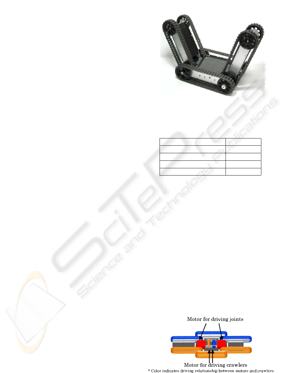
Our mobile mechanism has 3 connected stages with
the motor-driven crawler tracks on each side(Fig. 1).
The features of the proposed mechanism are as fol-
lows.
• This mechanism has high mobility to passing over
the obstacles.
• It can adjust the size of the robot.
• It can adjust the attack angle.
• It can minimize the grounding area.
Table. 1 also shows the specifications.
Figure 1: The overview of Connected crawler robot.
Table 1: Specifications of the test model.
Length(maximum) 354.0[mm]
Length(minimum) 118.0[mm]
Width 125[mm]
Mass 0.608[kg]
Radius of the sprockets 20.0[mm]
RC-servo motors are used for driving joints be-
tween the stages. The left and right crawlers are
driven by 2 DC motors independently, while the 3
crawlers on each side are driven by a motor simul-
taneously (Fig.2). The output of each motor is trans-
mitted to the sprockets of the three crawlers through
several gears.
2.2 Control Structure
We adopt a hierarchical control structure by installing
an intelligent servo driver to each actuator. We con-
nect each of them to the master contoll unit by UART
serial line. The parts marked by red line in Figure 3
are servo drivers. Each servo driver consists of one
Figure 2: The driving system.
DEVELOPMENT OF THE CONNECTED CRAWLER ROBOT FOR ROUGH TERRAIN - Realization of the
Autonomous Motions
397
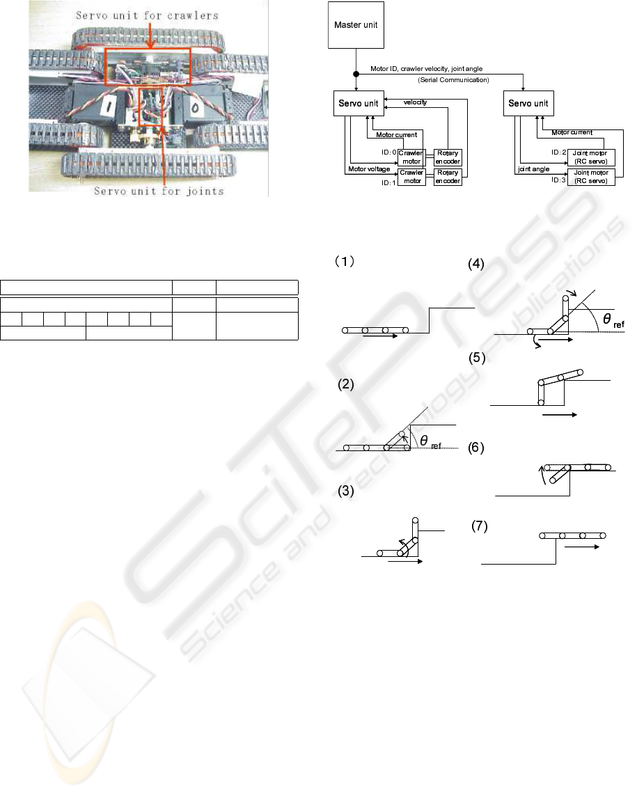
Figure 3: The overview of the servo unit.
Table 2: Communication data format.
1 byte 2 byte 3 byte
Data 1 Data 2 Check Sum
7 6 5 4 3 2 1 0
0∼254 Data1|Data2
Mode=0∼2 ID=0∼3
microcontroller (PIC16F873) and 2 DC motor drivers
(TA8440H). One microcontroller is installed to con-
trol the two RC-servo units for the joint control, where
RC-servo is controlled only by PWM signal.
Figure 4 shows the control structure of this sys-
tem. The master unit is equipped with several sen-
sors which are increnometers, PSD distance sensor
and photo reflector. The usage of these sensors will be
shown in Chapter 3. Master unit culclates high level
task (setting trajectory, sensing environment, etc), and
servo driver works for low level tasks. The master
unit processes the high level task, and derive the data
to low level task (crawler velocity, joint angel and so
on), and send them to the servo drivers. After receiv-
ing these data, the servo drivers control their motor
by conventional feedback control low. Table 2 shows
the communications data formats. The command sent
by master unit consists of 3 bytes. First byte indicates
mode ID and motor ID. The mode ID distinguishes
3 kinds of control modes: position control, velocity
control and compliance control. The motor ID is used
for selecting motor to control. Second byte shows the
data depends on control modes (crawler velocity, joint
angle). The third byte is checksum.
3 OPERATION STRATEGIES
A rough terrain such as disaster places has various
shapes. Hence, it is difficult to derive each au-
tonomous motion relative to each shape. But it can
Figure 4: The control system.
Figure 5: Proposed operation strategies.
be assumed that these shapes are consisted of many
bumps. Therefore, in this paper, we set the envi-
ronment to one bump, and consider about the oper-
ation strategies to climb up this one bump. Because
the climbing bump ability is important as one of the
most fundamental mobility index (Inoh, 2005), in ad-
dition climbing bump experiment is adopted by many
researches as an evaluation experiment for mobilities.
The proposed operation sterategies has 7 steps (Fig-
ure 5). It is low level operations(tasks), namely it is
not high level operations such as path planning etc. In
this paper we assume that the trajectory of the robot is
already given. Therefore the proposed operation deals
with how the robot can pass over the obstacles. Fol-
lowing sections will show the details of each steps.
ICINCO 2007 - International Conference on Informatics in Control, Automation and Robotics
398
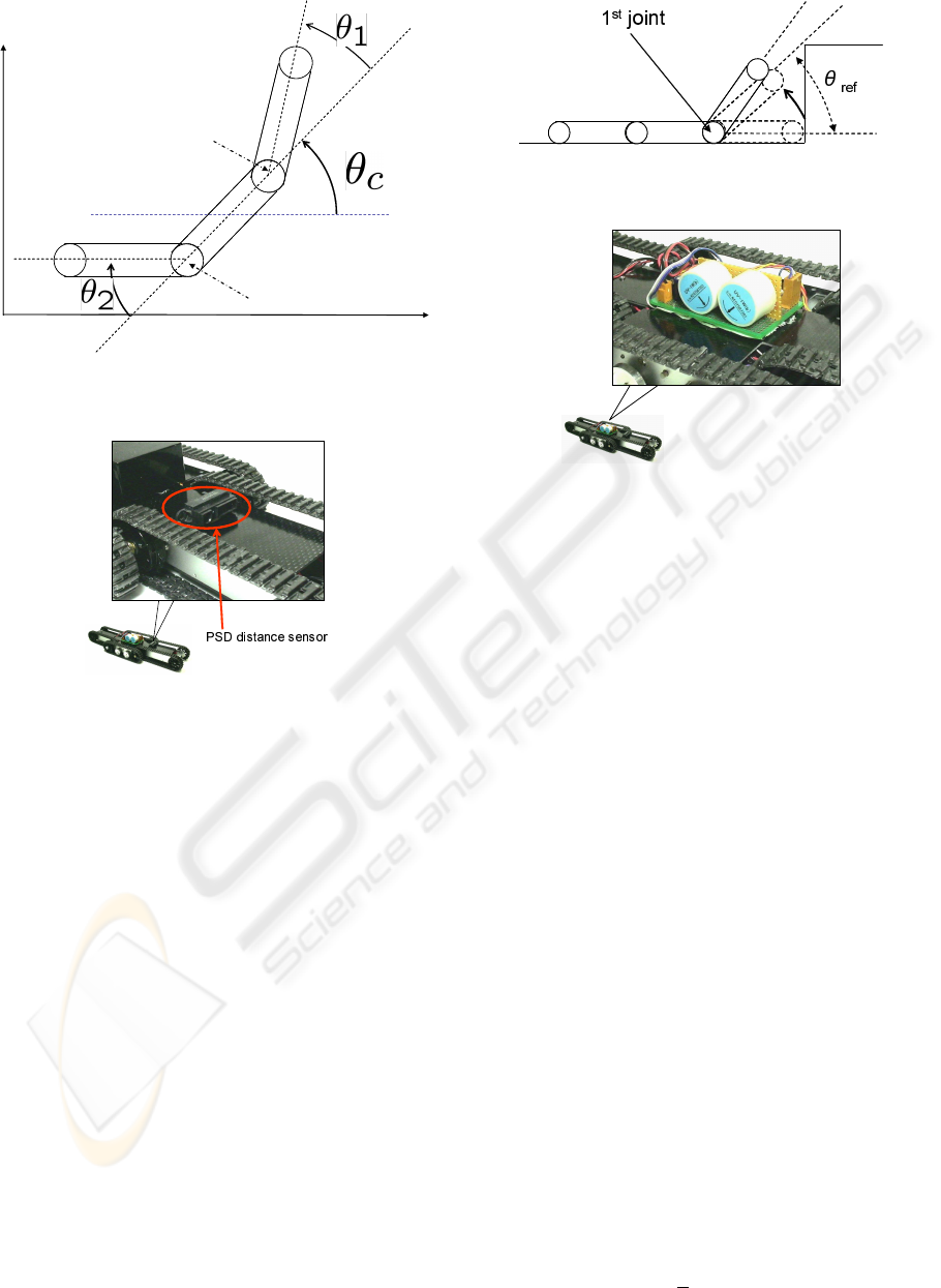
Center Stage
Front Stage
Rear Stage
2
nd
Joint
1
st
Joint
Figure 6: The definition of the parameters.
Figure 7: The PSD distance sensor.
Figure 6 is the difinition of the parameters. Here θ
c
is the orientation of the center stage. θ
1
and θ
2
are
the 1st and 2nd joint angle related to the θ
c
. Our pro-
posed operation sterategies can work by using only 3
very simple sensors.
3.1 First Step
First, the robot goes forward until detecting the wall.
If the robot faces the wall, then robot stops moving.
PSD distance sensor which is attached to the 1st stage
is used for detecting the wall (Figure 7). The informa-
tion of the PSD sensor is managed by the main con-
troller (Figure 4).
3.2 Second Step
In this step, 1st joint are driven to detect θ
ref
. θ
ref
is the 1st joint angle when the tangent of front stage
meets the edge of the bump (Figure 8).
Figure 8: The definition of θ
ref
.
Inclinometers
Figure 9: Inclinometers for detecting θ
c
.
3.3 Third Step
In third step, 2nd joint is driven while the robot goes
forward. The purpose of this step is to get the trac-
tion forces by keeping a grounding of rear stage. If
the robot goes forward without driving 2nd joint, then
robot could not get enough traction forces due to the
lift of rear stage. In order to keep the grounding of
rear stage, 2nd joint angle should be set to angle of
center stage, namely the 2nd joint is driven in the fol-
lowing condition.
θ
2
= θ
c
Here, the inclinometers which are attached to the cen-
ter stage are used to detect the angle of the center
stage (Figure 9).
3.4 Fourth Step
In this step, 1st joint angle is set to 0 rad, 2nd joint is
driven to let the angle between rear stage and ground
be right angle. At this moment, the robot continues
moving. There are two purpose in this step. One is to
obtain the traction forces, that is the role of 1st joint
motion. The other is to lift up the robot as high as
possible, that is the purpose of 2nd joint motion. 2nd
joint angle is determined by following condition. By
this condition, rear stage can always stand with keep-
ing right angle to the ground.
θ
2
=
π
2
− θ
c
DEVELOPMENT OF THE CONNECTED CRAWLER ROBOT FOR ROUGH TERRAIN - Realization of the
Autonomous Motions
399
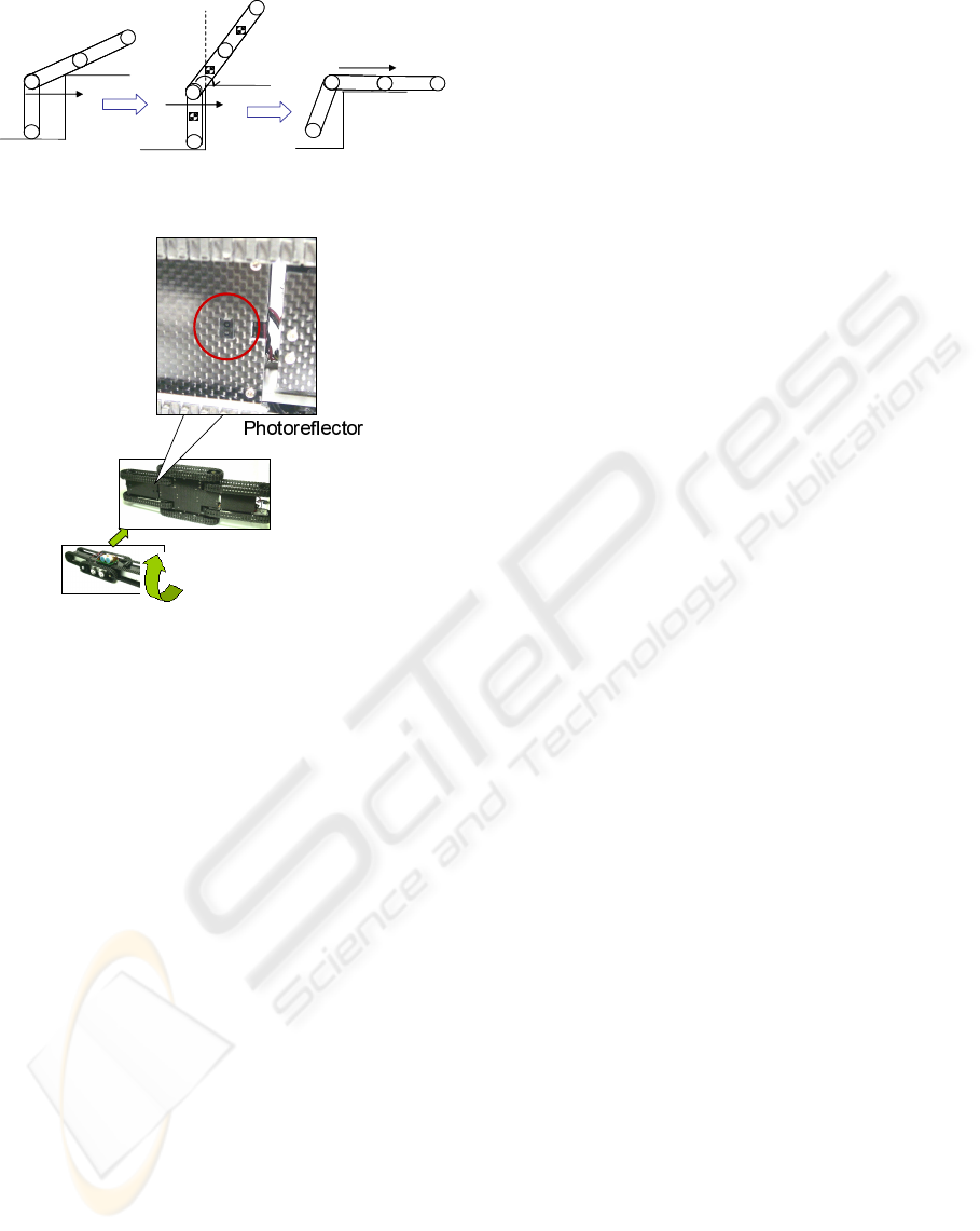
Figure 10: The situation of climbing up a bump.
Figure 11: Contact detection device.
The trigger to shift third step to fourth step is the θ
ref
.
In the third step, when the orientation of center stage
θ
c
is equal to θ
ref
, operation step is shifted.
3.5 Fifth Step
The robot goes forward with keeping above men-
tioned conditions. When the center of gravity of the
robot is in the right side of the bump edge, then the
clock wise moment is generated around the edge, the
robot can climb a bump. Figure 10 shows the situation
of this case.
3.6 Sixth and Seventh Step
At the end, 2nd joint angle is set to the initial position,
not to interfere robot’s moving. The trigger for this
motion is contact between bump and rear stage. The
photoreflector is adopted to detect this contact. This
photoreflector is attached to root and bottom of the
rear stage (Figure 11).
By above steps, climibing a bump is completed.
4 EXPERIMENTS
In order to confirm proposed operation strategies, ver-
ification experiments are conducted. We prepare two
kinds of experiments. One is that the robot passes
over two bumps with different height. The other is
stairs ascending. There are remarkable points in these
experiments. These experiment verifies whether the
robot can pass over the different height and different
structures obstacles by using only proposed strategies.
Moreover the sensors which realize proposed strate-
gies is very simple, and the number of sensor is very
small. Therefore if these experiments success, it can
be concluded that proposed strategies has extremely
high usefulness.
4.1 Passing Over the Different Hight
Bumps
In this chapter, the robot passes over the different
height bumps. The heights of bumps are 150 mm and
40 mm. The experimental environment is indoor, and
robot goes only forward, does not rotate and reverse.
We made the experiment by implementing proposed
strategies to main controller.
The result is shown in Figure 12. This Figure
shows that the robot can pass over the different hight
bumps autonomously.
4.2 Stairs Ascending
Next experiment is stairs ascending. The height be-
tween stairs is 150 mm, that is conventional stairs.
The implemented software to main controller is the
same as experiment in 4.1, namely we do not add any
modification, that is completely same. Then we con-
ducted the experiment.
The result is Figure 13. From this Figure, it
is turned out that the robot could ascend stairs au-
tonomously with driving joints.
5 CONCLUSIONS
The purpose of this research is to develop a rough ter-
rain mobile robot which can realize autonomous mo-
tion in disaster places. Especially, this paper proposed
autnomous operation strategy for passing over ob-
stacles, as well as constructing of connected crawler
robot as the first step of this research. The connected
crawler robot consisted of 3 crawler stages with ac-
tive joints. The operation strategies was proposed in
Chapter 3. This operation strategies was consisted
ICINCO 2007 - International Conference on Informatics in Control, Automation and Robotics
400
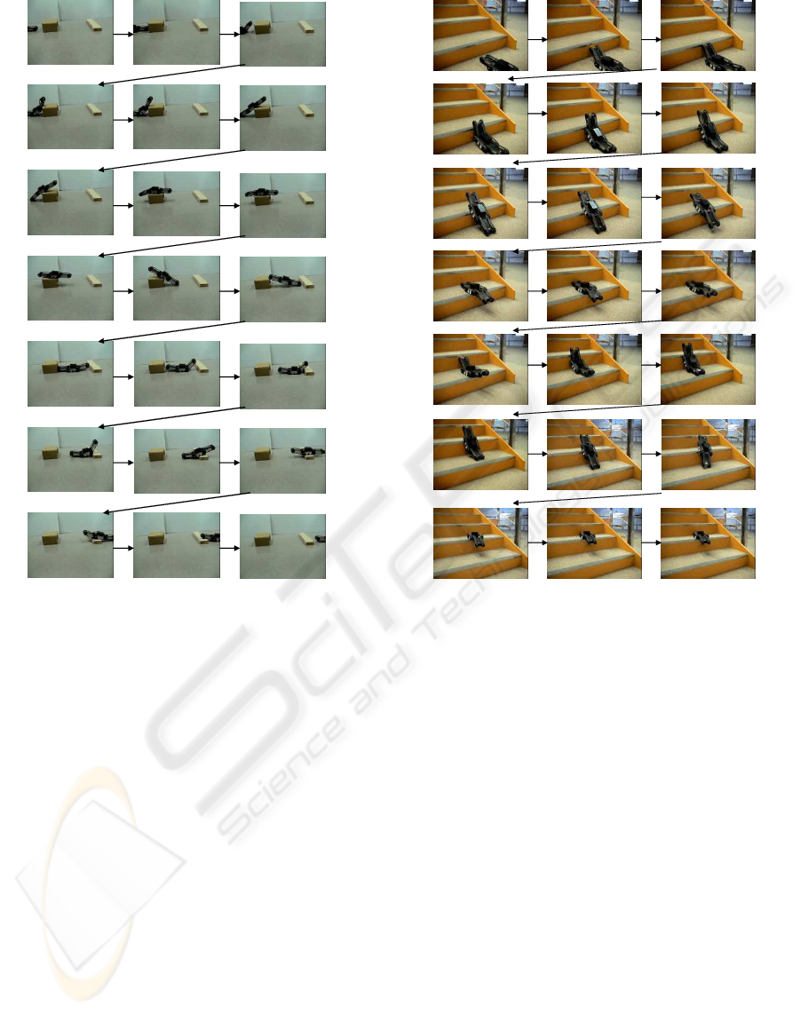
Figure 12: The experimental results of passing over bumps.
of 7 steps, and it needed only 3 simple sensor which
were PSD distance sensor, inclinometers and photore-
flectors. We have also made verification experiment
of proposed operation strategy. For this verification,
we did 2 types of experiments. One was that the robot
passes over bumps with different heights. The other
was stairs ascending.
Both experiments had a great success. There were
remarkable points in these experiments. These exper-
iments showed that the robot can pass over the dif-
ferent height and different structual obstacles by us-
ing only (same) strategy. Moreover the sensors which
realize proposed strategy were very simple, and the
number of sensor was very small. Therefore it can be
concluded that proposed strategy has extremely high
usefulness.
Future works: Proposed method was verified by
two experiments. In addition, we are going to verify
proposed method by many different types of experi-
ments. Moreover, this paper derived the autonomous
motion empirically. Therefore we have to analyze
motions of the passing over the obstacles as next step.
Figure 13: The experimental results of stairs ascending.
Furthermore we have to compare empirical results
and analytical results.
REFERENCES
Hirose, S. (2000). Mechanical Designe of Mobile Robot
for External Environments (in Japanese). Journal
of Robotics Society of Japan, Tokyo, vol.18, no.7,
pp904-908 edition.
Inoh, T. (2005). Mobility of the irregular terrain for resucue
robots. In 10th Robotics symposia. pp 39-44.
Lee, C. (2003). Double -track mobile robot for haz-
ardous environment applications. Advanced Robotics,
Tokyo, vol. 17, no. 5, pp 447-495, 2003 edition.
Osuka, K. (2003). Development of mobile inspection robot
for rescue activities:moira. In Proceedings of the 2003
IEEE/RSJ Intl. Conference on Intelligent Robots and
Systems. IEEE.
Takayama, T. (2004). Development of connected crawler
vehicle souryu-iii for rescue application. In Proc. of
22nd conference of Robotics Society of Japan CD-
ROM. Robotics Society of Japan.
DEVELOPMENT OF THE CONNECTED CRAWLER ROBOT FOR ROUGH TERRAIN - Realization of the
Autonomous Motions
401
