
GLOBAL ASYMPTOTIC VELOCITY OBSERVATION OF
NONLINEAR SYSTEMS
Application to a Frictional Industrial Emulator
R. Guerra
‡
, C. Iurian
⋆
, L. Acho
‡⋆
‡
Centro de Investigaci
´
on y Desarollo de Technolog
´
ıa Digital (CITEDI-IPN), Mexico
⋆
Universitat Polit
`
ecnica de Catalunya, Matem
`
atica Aplicada III, EUETIB, Barcelona, Spain
F. Ikhouane
†
and J. Rodellar
§
†
Universitat Polit
`
ecnica de Catalunya, Matem
`
atica Aplicada III, EUETIB, Barcelona, Spain
§
Universitat Polit
`
ecnica de Catalunya, Matem
`
atica Aplicada III, Barcelona, Spain
Keywords:
Velocity observers, friction, mechanical systems.
Abstract:
Development of velocity observers for mechanical systems with friction deserves a special emphasis, because
as evidenced in numerical and experimental tests when a state-of-the-art observer is armed, friction can in-
duce high-frequency oscillations in the estimated signal. In this short paper, two new velocity-observation
algorithms are designed, based on this previously reported observer, that eliminate the high-frequency oscilla-
tions noted. Numerical and experimental performance comparisons are carried through making use of LuGre
model and a mechanical PID control system that incorporates the estimated velocity into the feedback loop.
1 INTRODUCTION
Velocity-dependent control laws such as PD, PID, and
most robust control laws, among many others, the-
oretically require direct access to velocity. In reality,
there are many applications in which this is not availa-
ble either due to considerable manufacturing savings
in cost, weight, and volume, or because the velocity
measurements are highly contaminated with noise. In
the latter case, for instance when measuring robot
joint velocities, it may not even be desirable to do
so (Arteaga and Kelly, 2004). Consequently, if the
full-state information is missing, it is necessary to
estimate the unmeasurable velocity through the use
of an observer and feed it back into the controller.
Such is the case with the frictional industrial emula-
tor ECP model 220 used in our experiments. It has
been documented when studying mechanical closed-
loop control systems, that friction causes tracking
errors, limit-cycles, and stick-slip motions, among
other difficulties and usually unwanted phenomena
(Armstrong-H
´
etlouvry et al., 1994). As evidenced
in (Canudas de Wit and Fixot, 1991), (Canudas de
Wit and Fixot, 1992), (Berghuis and Nijmeijer, 1993),
and (Arteaga and Kelly, 2004) velocity observer de-
sign is a topic that has been and continues to be ex-
tensively studied. State observation of nonlinear ine-
xact plants has been treated by utilizing discontinu-
ous observers (Choi et al., 1999), (Xiong and Saif,
2001), and (Xian et al., 2004). However, little re-
search focused on velocity observation of mechan-
ical systems with friction at low velocities which,
when incorporating existing observers, exhibit high-
frequency oscillations in the velocity-estimation sig-
nal. A state-of-the-art, globally asymptotic, discon-
tinuous velocity-estimation scheme for second-order
mechanical systems has been presented in (Xian et al.,
2004). Though very reliable, this observer is not spe-
cialized for mechanical systems in the presence of
friction. Thus, a high-frequency component of the ve-
locity observation is detected when numerical simu-
lations and experimental testing are performed. The
two newly proposed observers claimed here are an
attempt to alleviate this unwanted oscillatory effect
and try offer an increase in the observation reliability.
The remainder of this document proceeds as fo-
llows: Section 2 postulates two modified observers
based on the velocity estimator stated in (Xian et al.,
2004). The next section presents numerical simu-
lations evidencing the performance of the observers.
Section 4 begins with a description of the frictional
experimental testbed, the ECP industrial emulator
85
Guerra R., Iurian C., Acho L., Ikhouane F. and Rodellar J. (2007).
GLOBAL ASYMPTOTIC VELOCITY OBSERVATION OF NONLINEAR SYSTEMS - Application to a Frictional Industrial Emulator.
In Proceedings of the Fourth International Conference on Informatics in Control, Automation and Robotics, pages 85-91
DOI: 10.5220/0001621100850091
Copyright
c
SciTePress

(ECP, 1995), and illustrates the results obtained when
implementing of the original observer as well as the
two modifications proposed in the PID mechatronic
system. Finally, conclusions are drawn in Section 5.
2 VELOCITY OBSERVATION
Consider a class of mechanical systems expressed by
(Xian et al., 2004)
¨x = h(x, ˙x) + G(x, ˙x)u, (1)
where x ∈ R is the system output, u(t) ∈ R is the
control input, and h(x, ˙x) ∈ R as well as G(x, ˙x) ∈ R
are nonlinear functions
1
. The system (1) satisfies the
following assumptions (Xian et al., 2004).
Assumption A1. Both h(x, ˙x) and G(x, ˙x) are C
1
functions.
Assumption A2. The control input is a C
1
function
and u(t), ˙u(t) ∈ L
∞
.
Assumption A3. The system state is bounded for all
time; i.e., x(t), ˙x(t) ∈ L
∞
.
The goal of the velocity observer is to estimate the
unmeasurable velocity signal ˙x(t) using only-position
measurement and assuming that h(x, ˙x), G(x, ˙x) and
u(t) are unknown (Xian et al., 2004). Let
˙
ˆx(t) ∈ R
be the estimated velocity and
˙
˜x = ˙x −
˙
ˆx the velocity
estimation error. Then, the objective of the velocity
observer is to ensure that
˙
˜x(t) converges to zero as the
time tends to infinity.
Consider the following velocity observer (Xian
et al., 2004)
˙
ˆx = p+k
0
˜x,
˙p = k
1
sgn( ˜x) + k
2
˜x,
(2)
where k
0
,k
1
, and k
2
are positive constants, and sgn(·)
is the signum function.
Remark 1. System (2) can be expressed as
˙y = f(y,x), y ∈ R
2
, x ∈ R
z = g(y, x), z ∈ R
where y = [ ˆx p]
T
, f(y, x) = [p + k
0
˜x k
1
sgn( ˜x) +
k
2
˜x]
T
, g(y,x) = p + k
0
˜x, and z =
˙
ˆx is the output
velocity estimation.
To state the main result in (Xian et al., 2004), let
N
0
(x, ˙x,t) = h(x, ˙x) +G(x, ˙x)u(t).
1
Without loss of generality, we have assumed a one-
degree-of-freedom (DOF) mechanical system.
Theorem 1 (Xian et al., 2004). The velocity observer
(2) ensures global asymptotic regulation of
˙
˜x(t) (i.e.,
˙
˜x(t) → 0 as t → ∞) provided that k
1
satisfies
k
1
> ||N
0
(x, ˙x,t)||
∞
+ ||
˙
N
0
(x, ˙x,t)||
∞
.
For detailed proof, see Theorem 2 in (Xian et al.,
2004). Let us now put forward the following observer
˙
ˆx = p+ k
0
˜x,
˙p = −k
1
sgn( ˜x) + k
2
˜x.
(3)
Theorem 2. The velocity observer (3) ensures global
asymptotic regulation of
˙
˜x(t) (that is,
˙
˜x(t) → 0 as
t → ∞) provided that k
1
satisfies exactly the same
conditions as in Theorem 1.
Proof. Identical to that of Theorem 1.
Another alternative proposal to the original observer
is the following
˙
ˆx = p+ k
0
˜x,
˙p = k
1
sgn( ˆx) + k
2
˜x.
(4)
Theorem 3. The velocity observer (4) also ensures
global asymptotic regulation of
˙
˜x(t) (i.e.,
˙
˜x(t) → 0
as t → ∞) on the condition that k
1
satisfies the same
restriction as in Theorem 1.
Proof. The same case as for the proof of Theorem 2
above.
These innovative observers are very similar to the one
in Theorem 1, but they present significant differences.
The observer in Theorem 2 introduces an inversion of
the sign in the estimation dynamic that produces a fil-
tering effect. The observer in Theorem 3 brings for-
ward an estimation error ˆx inside the signum function,
with the intent of reducing the high-frequency content
the error signal ˜x present in (2).
3 NUMERICAL EXPERIMENTS
Consider a linear motion of unit mass
¨x = u− f, (5)
where f is the friction force. Assuming for a moment
that f = 0 and k
1
= 10, the requirement imposed by
all theorems is satisfied. We complete the velocity
observers by setting k
0
= k
2
= 10. We also construct
the following PID controller, which makes the closed-
loop system globally asymptotically stable (if f = 0)
u = −k
p
(x− x
d
) − k
i
(x− x
d
)dt − k
d
˙x, (6)
ICINCO 2007 - International Conference on Informatics in Control, Automation and Robotics
86
with k
v
= 6, k
p
= 3, k
i
= 4, and the position reference
set at x
d
= 1 [m], see details in (Canudas de Wit et al.,
1995). Because friction force can produce limit cy-
cles within the system when the control law has an in-
tegrating action (Canudas de Wit et al., 1995), we in-
corporate a friction force in (5) by invoking the LuGre
model and its standard parameters given in (Canudas
de Wit et al., 1995); i.e., f is obtained as a nonlinear
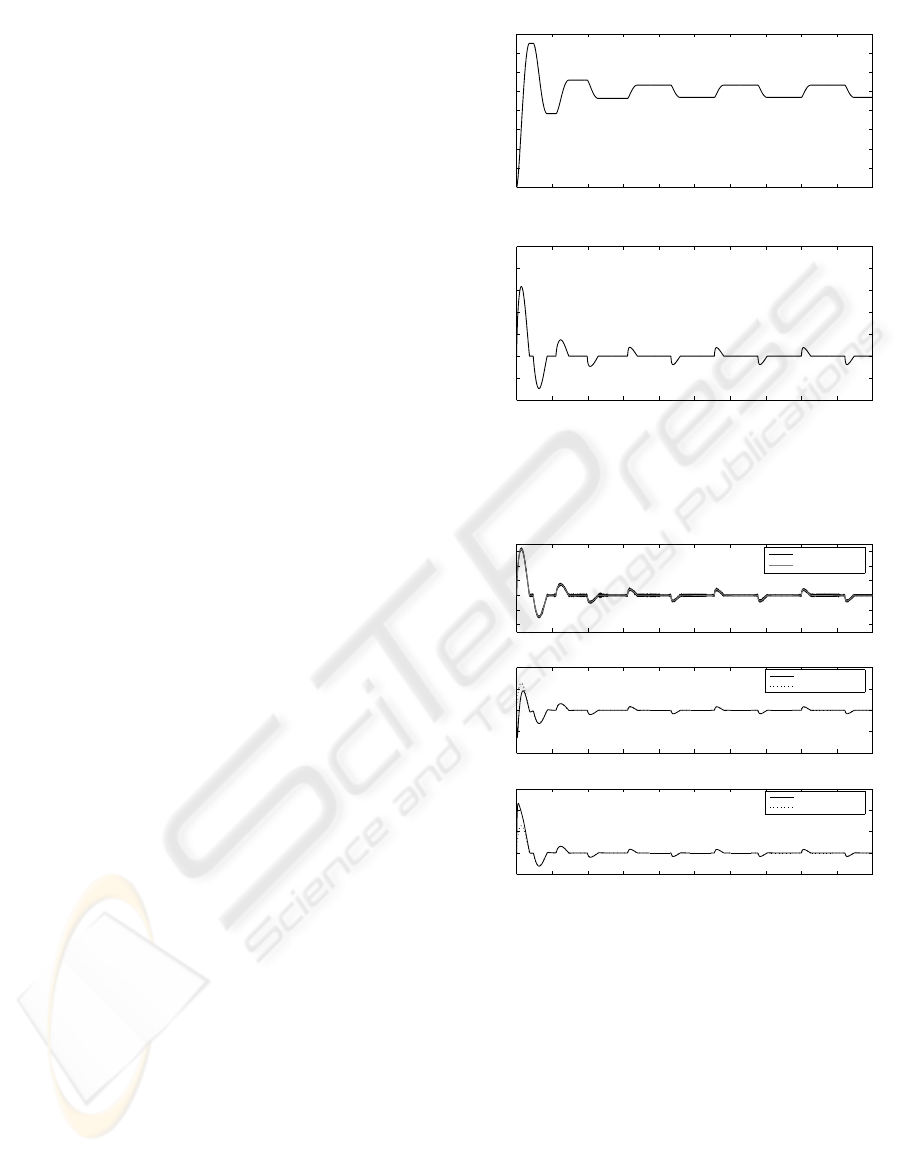
dynamic. Simulation results are depicted in Figure 1
where the position and velocity of the system are pic-
tured. These plots are a recreation of the experiment
presented in (Canudas de Wit et al., 1995). Obviously,
the PID controller (6) incorporates velocity measure-
ment, which for this simulation was assumed to be
available.
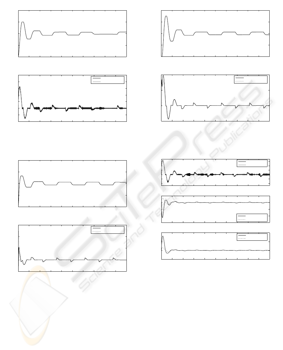
At this point, we repeated the previous simulation
using the true velocity in the control law and imple-
menting the three observers solely to estimate the ve-
locity, obtaining the results shown in Figure 2. Since
in the experimental application the velocity would
not be available for use, the simulation was again re-
peated, this time invoking the observers from Theo-
rems 1, 2, and 3 in the control law (i.e., replacing ˙x by
its corresponding
˙
ˆx in (6)). The results are portrayed
in Figures 3, 4, and 5, respectively. Note that cha-
ttering appears with the observer from Theorem 1 and
not with the others. It is important to stress that cha-
ttering is undesirable in a physical system because the
high-frequency switching can damage the system, as
well as activate unmodelled dynamics (G. Bartolini,
1998) and (Hung, 1993).
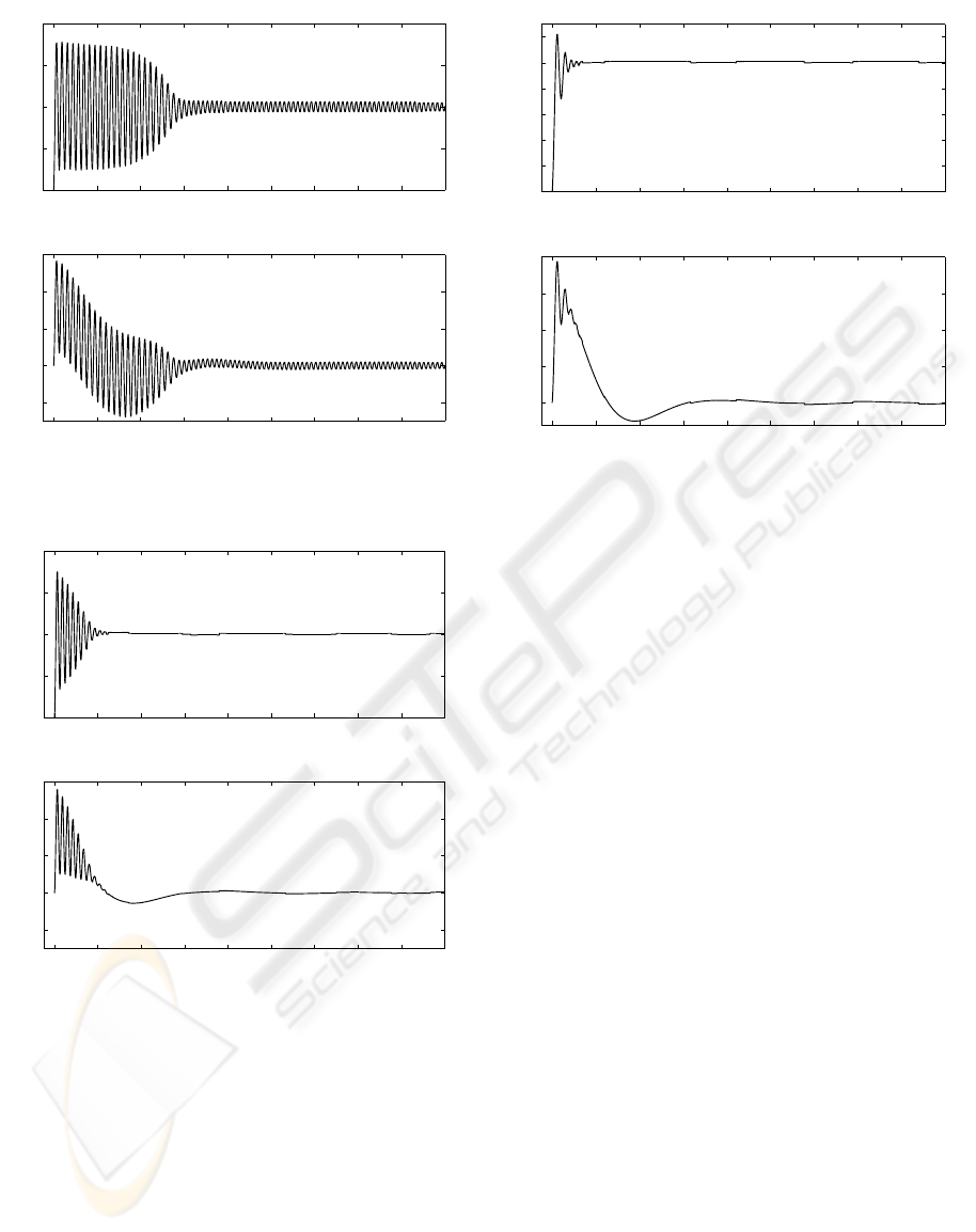
Let us return to the previously considered case
where the PID controller (6) is employed using the
exact velocity, which is only observed. If we slightly
modify the observer parameter values to k
1
= 5
and k
0
= k
2
= 1, the velocity observation obtained
with the observer in (2) becomes highly oscillatory
whereas the two observers proposed still provide
good results, as shown in Figure 6. If furthermore
we now feed the corresponding velocity estimation
into the PID controller (6), the first observer (stated
in Theorem 1) is much more sensible to variations in
its parameters. This causes instability of the closed-
control-loop (simulation pictures were then omitted
for the first case); nevertheless, the other two new ob-
servers yield acceptable good simulation results, see
Figures 7 and 8.
4 APPLICATION TO AN
INDUSTRIAL EMULATOR
To have a more realistic comparison among the ob-
servers stated in Section 2, we proceed to implement
0 10 20 30 40 50 60 70 80 90 100
0
0.2
0.4
0.6
0.8
1
1.2
1.4
1.6
Position [m]
Time [s]
0 10 20 30 40 50 60 70 80 90 100
−0.4
−0.2
0
0.2
0.4
0.6
0.8
1
Velocity [m/s]
Time [s]
Figure 1: PID position control of a second-order system
that incorporates Lugre friction model - see (Canudas de
Wit et al., 1995).
0 10 20 30 40 50 60 70 80 90 100
−0.4
−0.2
0
0.2
0.4
0.6
Velocity [m/s]
Xian et al. Velocity Observer
0 10 20 30 40 50 60 70 80 90 100
−1
−0.5
0
0.5
1
Velocity [m/s]
Proposed Velocity Observer from Theorem 2
0 10 20 30 40 50 60 70 80 90 100
−0.5
0
0.5
1
1.5
Velocity [m/s]
Time [s]
Proposed Velocity Observer from Theorem 3
Estimated velocity
Real velocity
Estimated velocity
Real velocity
Estimated velocity
Real velocity
Figure 2: Comparison of the three estimators (for k
0..
=
k
1
= k
2
= 10): 1) Top with Theorem 1, 2) Middle with
Theorem 2, and 3) Bottom with Theorem 3.
them on an experimentation testbed.
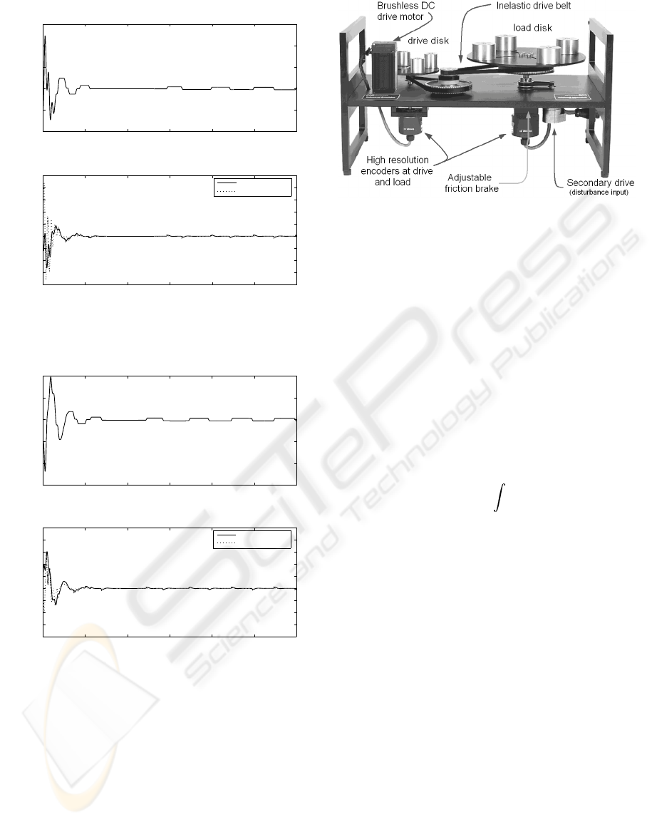
4.1 Experimental Setup
The experiments were performed on an ECP Model
220 industrial emulator which includes a PC-based
control platform and a DC brushless servo system
(ECP, 1995). The mechatronic system includes two
motors, one as servo actuator and the other as dis-
turbance input (not used here), a power amplifier,
and two encoders which provide accurate position
GLOBAL ASYMPTOTIC VELOCITY OBSERVATION OF NONLINEAR SYSTEMS - Application to a Frictional
Industrial Emulator
87
0 10 20 30 40 50 60 70 80 90 100
0
0.5
1
1.5
2
Position [m]
Time [s]
0 10 20 30 40 50 60 70 80 90 100
−0.4
−0.2
0
0.2
0.4
0.6
0.8
1
Velocity [m/s]
Time [s]
Estimated velocity
Real velocity
Figure 3: PID control incorporating velocity estimation
from Theorem 1.
0 10 20 30 40 50 60 70 80 90 100
0
0.5
1
1.5
2
Position [m]
Time [s]
0 10 20 30 40 50 60 70 80 90 100
−0.5
0
0.5
1
1.5
Velocity [m/s]
Time [s]
Estimated velocity
Real velocity
Figure 4: PID control employing velocity estimation given
in Theorem 2.
measurements; i.e., 4000 lines per revolution with
4× hardware interpolation giving 16000 counts per
revolution to each encoder; 1 count (equivalent to
0.000392 radians or 0.0225 degrees) is the lowest
angular position measurable (ECP, 1995). The sys-
tem was set up to incorporate inertia and friction
brake. The drive and load disks were connected via
a 4 : 1 speed reduction (see Figure 9). In order to
demonstrate that the system is subject to the noto-
rious effects of friction, we calculated according to
the procedure described by (R. Kelly and Campa,
0 10 20 30 40 50 60 70 80 90 100
0
0.5
1
1.5
2
Position [m]
Time [s]
0 10 20 30 40 50 60 70 80 90 100
−0.5
0
0.5
1
Velocity [m/s]
Time [s]
Estimated velocity
Real velocity
Figure 5: PID control utilizing the observer stated in Theo-
rem 3.
0 10 20 30 40 50 60 70 80 90 100
−0.4
−0.2
0
0.2
0.4
0.6
Velocity [m/s]
0 10 20 30 40 50 60 70 80 90 100
−3
−2
−1
0
1
Velocity [m/s]
0 10 20 30 40 50 60 70 80 90 100
−2
0
2
4
Velocity [m/s]
Time [s]
Estimated velocity
Real velocity
Estimated velocity
Real velocity
Estimated velocity
Real velocity
Figure 6: Comparison of the three estimators (for k
0..
=
k
2
= 1 and k
1
= 5): 1) Top with Theorem 1, 2) Middle with
Theorem 2, and 3) Bottom with Theorem 3.
2000) the following friction coefficients for the sys-
tem: F
v
= 0.05772[Nmsec/rad] (viscous friction co-
efficient) and F
c
= 0.43032[Nm] (Coulomb friction).
A Pentium 4, 2.80 GHz CPU, 512 MB RAM,
computer running under Windows XP is programmed
to implement the controller together with the in-
terface medium ECP USR Executive 5.1, a C-like
programming language (ECP, 1995). The system
contains a data-acquisition board for digital to analog
conversion and a counter board to read the position
encoder outputs into the servo system. The minimum
servo-loop closure sampling time T
s
is 0.884 ms.
ICINCO 2007 - International Conference on Informatics in Control, Automation and Robotics
88
0 25 50 75 100 125 150
−1
0
1
2
3
4
Position [m]
Time [s]
0 25 50 75 100 125 150
−4
−3
−2
−1
0
1
2
3
4
5
Velocity [m/s]
Time [s]
Estimated velocity
Real velocity
Figure 7: PID control containing the velocity as given by
Theorem 2.
0 25 50 75 100 125 150
−2
−1
0
1
2
3
Position [m]
Time [s]
0 25 50 75 100 125 150
−4
−3
−2
−1
0
1
2
3
4
5
Velocity [m/s]
Time [s]
Estimated velocity
Real velocity
Figure 8: PID control making use of the observer in Theo-
rem 3.
The output voltage signal generated by the system
is in the range of ±5V and is delivered to the motor
drive via the DAC, the measurement feedback is a
position signal (in counts or radians), measured at the
shaft of each of the two disks by the optical rotary
incremental position encoders, then it is read by the
microcomputer by means of the counter board and
delivered into the PC. A software interface has been
built to easily transfer the raw data collected from the
plant (by means of the ECP USR Executive program)
to the Matlab workspace environment, in order to
Figure 9: Mechanical system with friction.
display the results. The load disk is weighted with
4 masses of 0.50 kg each (at a radius of r = 10.0
cm) while the drive disk remains unweighted (see
Figure 9). It is worth mentioning that the mechanical
system has encoders which give accurate position
measurements, nevertheless no direct velocity sens-
ing is available (ECP, 1995). In this scenario, we
implemented the aforementioned velocity observers,
obtaining the results pictured in Figures 10 – 12.
4.2 Experimental Results
The implemented control law is as follows
u = −k
p
(x− x
d
) − k
i
(x− x
d
)dt − k
d
˙
ˆx,
with k
d
= 0.0011, k
p
= 0.135, and k
i
= 0.4.
The desired reference position was set to
x
d
= 100 [counts] = 0.0392 [rad] = 2.25 [deg].
As it can be noted in Figure 10, when the observer
stated in Theorem 1 is employed, this produces an os-
cillation of relatively high-frequency and amplitude
into the system. The observer (4), after the transient,
eliminates both the amplitude and the frequency of
this oscillation (Figure 11). The estimator from The-
orem 3 further reduces the amplitude and duration of
the transient, even more than observer (4), eliminat-
ing chattering as seen in Figure 12. Moreover, note
that the position limit cycles in Figures 11–12, caused
by friction in PID control of servo drives (Canudas
de Wit et al., 1995), have the same rectangular-like
waveform pattern as in Figure 1, and can be distinctly
identified.
5 CONCLUSIONS
Two new velocity-observation designs are presented,
and experimentally validated, for use in mechanical
GLOBAL ASYMPTOTIC VELOCITY OBSERVATION OF NONLINEAR SYSTEMS - Application to a Frictional
Industrial Emulator
89
0 2 4 6 8 10 12 14 16 18
0
50
100
150
200
Output Position [count]
Time [s]
0 2 4 6 8 10 12 14 16 18
−200
0
200
400
600
Observed Velocity [count/sec]
Time [s]
Figure 10: Experimental results using the observer from
Theorem 1.
0 2 4 6 8 10 12 14 16 18
0
50
100
150
200
Output Position [count]
Time [s]
0 2 4 6 8 10 12 14 16 18
−200
0
200
400
600
Observed Velocity [count/sec]
Time [s]
Figure 11: Experimental results employing the observer
from Theorem 2.
systems with friction where only-position measure-
ments are available. As it can be appreciated from
numerical and experimental results, the proposed ob-
server schemes are more efficient than their precur-
sor in that chattering is eliminated from the velocity-
observed signal. It is worth emphasizing that the pre-
sented observers (3) and (4) are especially interest-
ing for industrial purposes, for they assure that the
velocity-acquisition hardware can, without difficulty,
be replaced by an analogous inexpensive software
performing the same function.
0 2 4 6 8 10 12 14 16 18
0
20
40
60
80
100
120
Output Position [count]
Time [s]
0 2 4 6 8 10 12 14 16 18
0
100
200
300
400
Observed Velocity [count/sec]
Time [s]
Figure 12: Experimental results utilizing the observer from
Theorem 3.
ACKNOWLEDGEMENTS
This work was supported by CICYT through Grant
DPI2005-08668-C03-01. The work of F. Ikhouane
was supported by Spanish Ministry of Science and
Education under “Ram
´
on y Cajal” Program.
REFERENCES
Armstrong-H
´
etlouvry, B., Dupont, P., and Canudas de Wit,
C. (1994). A survey of models, analysis tools and
compensation methods for the control of machines
with friction. Automatica, 30(7):1083–1138.
Arteaga, M. A. and Kelly, R. (2004). Robot control without
velocity measurements: new theory and experimental
results. IEEE Trans. Robot. Automat, 20(2):297–308.
Berghuis, H. and Nijmeijer, H. (1993). Global regulation of
robots using only position measurements. In Systems
and Control Letters. vol. 21, no. 4, pp. 289–293.
Canudas de Wit, C. and Fixot, N. (1991). Robot control via
robust estimated state feedback. In IEEE Trans. on
Aut. Control. vol. 36, no. 12, pp. 1497–1501.
Canudas de Wit, C. and Fixot, N. (1992). Adaptive control
of robot manipulators via velocity estimated feedback.
In IEEE Trans. on Aut. Control. vol. 37, no. 8, pp.
1234–1237.
Canudas de Wit, C., Olsson, H.,
˚
Astr
¨
om, K. J., and Lischin-
sky, P. (1995). A new model for control of systems
with friction. In IEEE Trans. on Aut. Control. vol. 40,
no. 3, pp. 419–425.
Choi, J., Misawa, E., and Young, G. (1999). A study on slid-
ing mode state estimation. J. dyn. syst. meas. control,
121:255–260.
ICINCO 2007 - International Conference on Informatics in Control, Automation and Robotics
90

ECP (1995). Manual for model 220 industrial emula-
tor/servo trainer. In Educational Control Products.
California 91367, USA.
G. Bartolini, A. Ferrara, E. U. (1998). Chattering avoidance
by second-order sliding mode control. In IEEE Trans.
on Automatic Control. vol. 43, no. 2, pp. 241–246.
Hung, J. C. (1993). Chattering handling for variable struc-
ture control systems. In Proc. of the IECON ’93. vol.
3, pp. 1968–1972, Maui, Hawaii, USA.
R. Kelly, J. L. and Campa, R. (2000). A measurement pro-
cedure for viscous and coulomb friction. In IEEE
Trans. Instrum. Meas. vol. 49, no. 4, pp. 857–861.
Xian, C., de Queiroz, M. S., Dawson, D. M., and McIntyre,
M. L. (2004). A discontinuous output controller and
velocity observer for nonlinear mechanical systems.
In Automatica. 40, pp. 695–700.
Xiong, Y. and Saif, M. (2001). Sliding mode observer
for nonlinear uncertain systems. IEEE Trans. on Aut.
Control, 46(12):2012–2017.
GLOBAL ASYMPTOTIC VELOCITY OBSERVATION OF NONLINEAR SYSTEMS - Application to a Frictional
Industrial Emulator
91
