
INTEGRATING SOFTWARE ARCHITECTURE CONCEPTS
INTO THE MDA PLATFORM
Alti Adel, Khammaci Tahar, Smeda Adel and Bennouar Djamal
LINA, University of Nantes
2 Rue de la Houssinière, BP 92208
44322 Nantes Cedex 03, France
Keywords: Software Architecture, COSA, MDA, CORBA, UML profile, Mapping rules.
Abstract: Architecture Description Languages (ADLs) provide an abstract representation of software systems.
Achieving a concrete mapping of such representation into the implementation is one of the principal aspects
of MDA (Model Driven Architecture). Integration of ADLs within MDA confers to the MDA platform a
higher level of abstraction and a degree of reuse of ADLs. Indeed they have significantly different platform
metamodels which make the definition of mapping rules complex. This complexity is clearly noticeable
when some software architecture concepts cannot be easily mapped to MDA platform. In this paper, we
propose to integrate software architecture within MDA. We define also strategy for direct transformation
using a UML profile. It represents both software architecture model (PIM) and MDA platform model (PSM)
in UML meta-model then elaborates transformation rules between results UML meta-models. The goal is to
automate the process of deriving implementation platform from software concepts.
1 INTRODUCTION
Software architecture description provides an
abstract representation of components and their
interactions of a software system by means of
Architecture Description Languages (ADLs)
(Medvidovic and Taylor, 2000). This technique is
called Component-Based Software Architecture
(CBSA). CBSA helps software architects to abstract
the details of implementation and facilitates the
manipulation and the reuse of components.
Actually, there are several middleware platforms
(CORBA
, J2EE, NET, etc.) that focus on developing
component-based systems. Communication among
components is complex between heterogeneous
platforms and the reuse of components in the
implementation level is therefore limited.
During last decade, UML becomes a standard
lan
guage for specifying, visualizing, constructing
and documenting architectural description concepts
(Object Management Group, 2004). However, UML
lacks the support for some architectural concepts
such as connectors, roles, etc, but it provides a
suitable base to define profiles for software
architecture and implementation platforms.
The notion of transformation is an essential
ele
ment for Model Driven Architecture (MDA)
(Fuentes-Fernández and Vallecillo-Moreno, 2004),
aiming at automated model transformations.
Furthermore, UML profiles can be integrated within
a MDA context to define a chain of model
transformations, from architecture to implementation
(Model Driven Architecture, 2003); (Fuentes-
Fernández and Vallecillo-Moreno, 2004).
Given the central importance of integrating
Soft
ware Architecture (SA) concepts into MDA
platform, concepts of the ADL are considered as
PIM and explored in MDA platform as PSM. The
different metamodels with different architecture
concepts make the transformation rules complex. In
this article, we try integrate SA concepts into MDA
platform. We also discuss the usefulness and the
importance of standard UML profiles in the
definition of mapping rules between software
architecture elements and its corresponding
implementation elements for a given MDA platform.
Our strategy focuses on separation of different
abstraction levels, translates and integrates SA
concepts into MDA platform more easily and more
quickly.
144
Adel A., Tahar K., Adel S. and Djamal B. (2007).
INTEGRATING SOFTWARE ARCHITECTURE CONCEPTS INTO THE MDA PLATFORM.
In Proceedings of the Second International Conference on Software and Data Technologies - SE, pages 144-149
DOI: 10.5220/0001345201440149
Copyright
c
SciTePress
The remainder of this article is organized as
follows. In Section 2 we present a model of SA
(COSA software architecture) and its UML profile.
Section 3 presents the integration of COSA software
architecture concepts into MDA platform with a
definition of a strategy of direct transformation using
profile and illustrates it by a COSA-CORBA
transformation. Section 4 summarizes related work.
Finally, Section 5 concludes this article and presents
some future works.
2 COSA: A MODEL OF
SOFTWARE ARCHITECTURE
Component-Object based Software Architecture
(COSA) describes systems as a collection of
components that interact with each other using
connectors. Components and connectors have the
same level of abstraction and are defined explicitly.
COSA takes into account most of operational
mechanisms used in the approach object-oriented
such as instantiation, inheritance, composition, etc
(
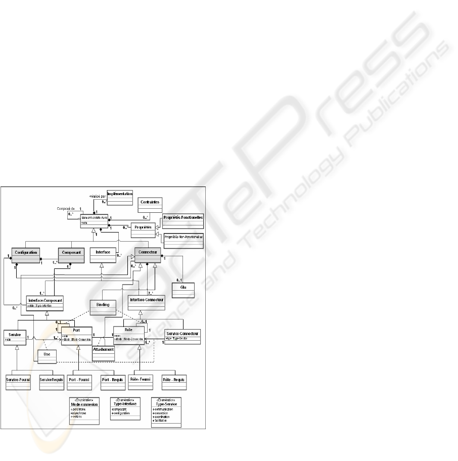
Oussalah, Smeda and Khammaci, 2004). Figure 1
presents a model of the COSA software architecture.
Figure 1: Meta model of the COSA approach.
2.1 COSA Architectural Concepts
COSA supports number of architectural elements
including configurations, components, connectors,
interfaces, properties and constraints (
Oussalah,
Smeda and Khammaci, 2004). These architectural
elements are types that can be instantiated to
construct several architectures.
The key role of configurations in COSA is to
abstract the details of different components and
connectors. Components represent the computational
elements and data stores of a system. A component
can be primitive or composite. Connectors represent
interactions among components. A COSA connector
is mainly represented by an interface and a glue
specification. In principle, the interface shows the
necessary information about the connector,
including the roles, service type that a connector
provides (communication, conversion, coordination,
facilitation). Connectors can be composite or
primitive. Interfaces in COSA are first-class
entities. They provide connection points among
architecture elements. Properties represent additional
information (beyond structure) about the parts of an
architectural description. There are two types of
properties: functional properties and non-functional
properties. Functions that relate to the semantics of a
system and represent the requirements are called
functional properties. Meanwhile non-functional
properties represent additional requirements, such as
safety, security, performance, and portability.
Constraints are specific properties, they define
certain rules and regulations that should be met in
order to ensure adherence to intended component
and connector uses.
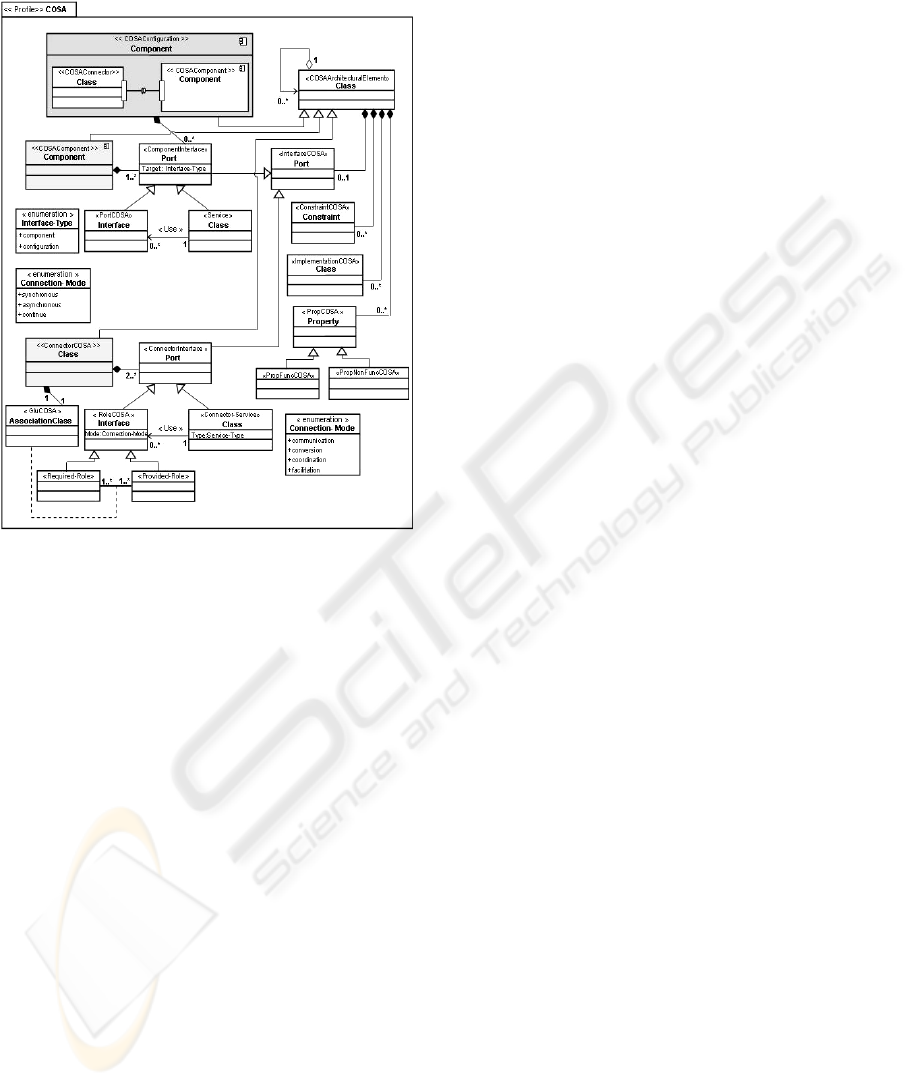
2.2 COSA UML Profile
The goal of the COSA profile (Alti, Khammaci and
Smeda, 2007) is to extend UML 2.0 in order to
represent COSA architectural concepts. This profile
aims to define software architecture concepts in
MDA framework.
A high level profile model provides the basic
concepts to define COSA architecture. The meta-
model of COSA is described as a UML stereotype
package named «COSA». This package defines
number of stereotypes: «COSAComponent»,
«COSAConnector», etc. These stereotypes
correspond to the metaclasses of UML meta-model
with all tagged values and its OCL 2.0 constraints.
Figure 2 shows this meta-model. The second level
permits to describe a particular architecture with the
application of the profile. We can also define the
value of each tagged value related to each
stereotype. In this level the OCL constraints are
checked and the final mapped system must conform
to the UML profile. The third level presents a set of
INTEGRATING SOFTWARE ARCHITECTURE CONCEPTS INTO THE MDA PLATFORM
145
instances for component, connector, and
configuration types.
Figure 2: The COSA UML profile.
3 INTEGRATION OF COSA
SOFTWARE ARCHITECTURE
CONCEPTS INTO MDA
MDA (Model Driven Architecture) provides means
to separate preoccupations of architectural aspects
from implementation aspects by supporting the
automation of the transformation from modelling to
implementation. The main point is the independent
of the model definition from the implementation
platforms (CORBA, J2EE, etc.).
MDA Platform provides simplicity of
development by assembling prefabricated
components but it does not support high levels of
abstraction, especially composite components and
connector concept. Most software architecture
models such as COSA support composite
components and define connectors explicitly as
abstract concepts. Hence, it is very useful to define
an automatic transformation from SA model (as an
MDA PIM) to platform model (as an MDA PSM).
The primary interest is a rapid mapping and smooth
integration of software architecture concepts into
MDA platforms to achieve a higher level of
abstraction and to help solving the problems of
interactions among heterogeneous components.
Comparing to SA model, platform has concrete
aspects and fully realizing designs.
MDA takes into account the architecture
description language as COSA; while integrating
their description in two abstraction levels, at the PIM
(Platform Independent Model) and in the PIM
transformations toward PSM (Platform Specific
Model).
Software architecture at the PIM level: PIM
meta-model includes all architectural concepts
relative to the COSA model. Using the mechanisms
provided by UML profiles, we realize PIM
transformations toward PSM and integrates all
software architecture concepts into MDA platforms.
Software architecture at the PSM level: the PIM
transformations into PSM specify the way of which
the MDA platforms (CORBA, J2EE, etc.) using
models of COSA architectures contains all intended
architectural concepts for exploitation.
3.1 Profile Transformation
Let us transform the COSA architecture model as
PIM, which conforms to the COSA-metamodel, into
another model of specific MDA platform which
conforms to another metamodel (PSM). PIM and
PSM have not the same architecture concepts. That
makes the transformation rules between models
more complex. Consequently, we propose means of
direct profile transformations to facilitate the
elaboration of architectural concepts.
The mechanisms provided by UML profiles are
very well suited to describing any implementation
platform and the transformation rules between
models. The definition of transformation process
starts with defining a UML model conforms to the
COSA meta-model, next producing automatically an
implementation UML platform model as a target
platform. After that, the model is evaluated by the
platform profile.
We need to define the mapping rules from
elements of the PIM to elements of PSM that make
up the platform profile. The idea of elaborating these
rules is to take each UML element of a PIM and find
its corresponding PSM (the same semantically UML
elements of PIM). Each element of transformation
contains OCL expression (Object Management
Group, 2005), which permits transformation
between the elements of COSA UML profile and
platform UML profile and a filter to permit
distinction between them. In addition, if the UML
profile of the platform includes the specification of
ICSOFT 2007 - International Conference on Software and Data Technologies
146
element relationships, then the transformation may
be specified using operations deduced from theses
relationships.
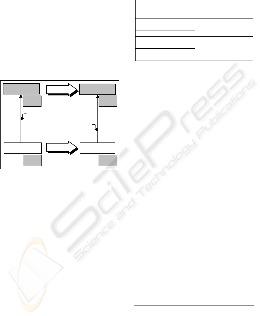
3.2 Illustrated Transformation: From
COSA (PIM) to CORBA (PSM)
To illustrate how our strategy of mapping can be
used, we apply it to COSA (PIM) to CORBA
(Object Management Group, 2002) (PSM)
transformation. Figure 3 presents the process of
transformation from COSA software architecture to
CORBA standard platform.
Figure 3: COSA (PIM) to CORBA (PSM) transformation.
3.2.1 Correspondence Concepts
COSA UML profile (Alti, Khammaci and Smeda,
2007) and CORBA UML profile (Object
Management Group, 2003) are based on two
different UML meta-models; we need to map each
COSA concept into CORBA concepts.
The COSA-CORBA correspondence can be
deduced easily from the same semantics between
UML elements. COSA components are represented
by UML 2.0 components. Since UML 2.0
component corresponds to a UML 1.4 class (the
name of the class is the name of the component), a
UML 2.0 component «COSAComponent» may be
transformed to UML class «CORBAHome». COSA
connectors, which are abstractions that include
mechanisms of communication, are not defined
explicitly in CORBA platform; we tried to find the
closest CORBA concepts semantically. COSA
connectors are represented by UML 2.0 classes.
Since UML 2.0 class matches UML 1.4 class, so
UML 2.0 Class «COSAConnector» is mapped to
UML class «CORBAHome». Table 1 shows the
main concepts of COSA and their CORBA
correspondence.
Table 1: COSA-CORBA correspondence.
COSA concepts CORBA Concepts
«COSAConfiguration»
Component
«CORBAModule»
Package
«COSAComponent»
Component
«COSAConnector» Class
«CORBAHome»
Class
«Component-Interface»
Port
«Connector-Interface»
Port
«CORBAComponent»
Class
3.2.2 Mapping Rules
Mapping rules must follow COSA to CORBA
correspondence concepts. To elaborate each
mapping rule we affect all elements relationships of
source model (COSA) to its corresponding
relationships on the target model (CORBA).
MM
UML2.0
M
COSA
M
CORBA
Run
PIM
COSA Profile
UML2.0
CORBA Profile
UML1.4
MM
UML1.4
Definition
PIM
PSM
PSM
For example COSA connectors, which are
abstractions that include mechanisms of
communication, are not defined explicitly in
CORBA platform, for this we tried to find the
closest CORBA concept (i.e. semantically). COSA
connectors are represented by UML 2.0 classes that
match with UML 1.4 classes. Therefore, UML 2.0
Class «COSAConnector» is mapped into UML class
«CORBAHome» and when elaborating the mapping
rule from UML 2.0 stereotyped class
«COSAConnector» to UML stereotyped class
«CORBAHome» we include operations for
acquiring attached elements (getCOSAProps for
acquired component properties, getCOSAImps for
acquired component implementations and
getCOSAContsraints for acquired component
constraints) because COSA connectors contain only
properties, implementations and constraints, and
then we impose this to the corresponding CORBA
element. Figure 4 shows this mapping rule in ATL.
(ATLAS group LINA and INRIA Nantes, 2006).
Rule COSAConector2CORBAHome {
from inConn : UML2!Component
(inConn. hasStereotype(‘COSAConnector’))
to outHome:UML14!Class (
name <- inConn.name,
feature<-inConn.getCOSAProps(),
constraint<-inConn.getCOSAConsts(),
clientDependency <-inConn.getCOSAImps(),
stereotype <-‘CORBAHome’
)
}
Figure 4: Example of mapping rule from COSA to
CORBA transformation using ATL.
INTEGRATING SOFTWARE ARCHITECTURE CONCEPTS INTO THE MDA PLATFORM
147
3.2.3 Implementing the Transformation
We have developed a Plugin-In in BM Rational
Software Modeler (RSM) for Eclipse 3.1 to
implement the COSA to CORBA transformation.
The Plug-In is developed in four steps: 1) the meta-
model of COSA (and CORBA) with all tagged
values and OCL constraints is defined by the UML
2.0 (UML 1.4) profile. 2) The COSA-CORBA
transformation is created. This transformation
describes how COSA model elements are matched
and navigated, to create and initialize the elements
of CORBA models. 3) COSA model is created by
UML 2.0 components diagram, evaluated by its
profile 4) COSA to CORBA transformation is
configured and executed. The elaborated CORBA
model is evaluated by its profile.
COSA-CORBA transformation is defined using
ATL transformation language (ATLAS group LINA
and INRIA Nantes, 2006) of RSM. To illustrate the
transformation, we elaborated the client-server
system by a components diagram and OCL
constraints. The model is validated by COSA
profile. The COSA-CORBA transformation is
applied to the COSA model for elaborating its
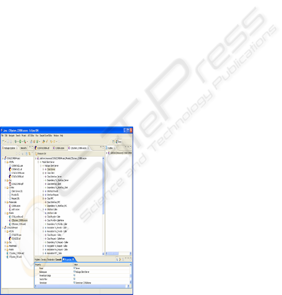
correspondent CORBA model. Figure 5 shows the
applied CORBA model of Client-Server system.
Figure 5: The CORBA model for Client-Server system
after applying transformation.
4 RELATED WORK
In (Garlan, 2000), Garlan points out that the world
of software development and the context in which
software is being used are changing in significant
ways, and these changes promise to have a major
impact on how architecture is practiced. Rodrigues
and al (Rodrigues, Lucena and Batista, 2004)
defined a mapping rules to transform an ACME
description into a CORBA IDL specification. They
focused on composing systems by exploring the
ACME extensions facilities to include input/output
ports in an ACME specification. They transformed
almost every thing as an IDL interface, therefore,
they did not really profit from the concepts available
in CORBA IDL. Manset and al (Manset, Verjus,
McClatchey and Oquendo, 2006), defined a formal
architecture-centric model-driven development
(ACMDD) process on top of the powerful
architecture description languages and platform,
ArchWare. They used a formal semantics for
building architectural models and refining to multi-
layered architecture specifications. (ACCORD
RNTL Project, 2002) is an open and distributed
environment that aims to ease assembling
components. It defines a semi-automated matching
of concepts and an automated transformation of
ACCORD model into CCM. This work is based on
UML profiles to represent ACCORD and CCM
architectural concepts. It defines an intermediate
filter model for adapting transformation process.
Then assembling components are defined using
XML files, this makes it difficult to promote
components reuse. Marcos and al (Marcos, Acuňa
and Cuesta, 2006), integrated true architectural
design aspects in MDA architecture and followed a
transformation approach on the level of architecture
models from Platform- Independent Architecture
models (PIAs) free from all technological
constraints to a Platform-Specific Architecture
models (PSAs) depending on specific needs and
technologies. They studied the integration software
architecture as a new aspect at PIM and PSM levels
into MDA for better manageability and
administration. Its approach allows a well separation
between differentes aspects, but disagrees in the
more integration of architecture concepts and
architectural styles available in ADLs. More
recently, in (Sánchez, Magno, Fuentes, Moreira and
Araújo, 2006) Sánchez proposed an automatic
transformation between requirement and architecture
models for achieving a comfortable MDA
framework.
ICSOFT 2007 - International Conference on Software and Data Technologies
148

Our approach of profile transformations can be
seen as a base for mapping architectural concepts
into an implicational plat-form. It offers number of
advantages compared to related works, including:
- fast mapping and smooth integration of
most of SA concepts especially the
concepts that are not defined explicitly such
as connector, configuration, roles, to
achieve a complete MDA framework,
- satisfying the higher level of abstraction of
MDA plate-form by adopting high
abstraction level from the UML Profile,
- automatic elaboration rules at the
transformation process by using the same
UML meta-models,
However, our approach does not include the
description architectural styles available and the
capacity of automatic elaboration of the
correspondence specification concepts between
MDA PIM and MDA PSM meta-models for the
transformation process.
5 CONCLUSION
In this paper, we propose the integration of software
architecture concepts into MDA platform and also
we define a strategy of direct transformation using
UML profile by mapping software architecture
model and platform models in UML meta-model
then elaborate correspondences concepts between
results UML meta-models in mapping rules. We
illustrated our strategy using an automatic
transformation from COSA concepts to CORBA
concepts. This strategy allows the mapping of
COSA software architecture concepts that are
specified in the UML profile (PIM) into CORBA
platform (PSM).
Related benefits of profile transformations is a
higher abstraction level of MDA platform and more
easily and more quickly integrating architectural
concepts within MDA. Currently, we are
elaborating portable IDL files from result CORBA
model. In our future works we will apply profile
transformation in the other MDA platform and in the
other SA-based.
REFERENCES
ACOORD RNTL Project., 2002.
http://www.infres.enst.fr/projet/accord
ATLAS group LINA and INRIA Nantes., 2006. ATL:
Atlas Transformation Language, ATL User Manual
version 0.7.
Alti, A., Khammaci, T., and Smeda, A., 2007.
Representing and Formally Modeling COSA software
architecture with UML 2.0 profile, IRECOS Review,
Vol. 2, No 1, pp. 30-37, ISSN: 1828-6003.
Fuentes-Fernández, L., Vallecillo-Moreno, A., 2004. An
Introduction to UML Profiles. The European Journal
for the Informatics Professional, 7(2), pp. 6-13.
Garlan, D., 2000. Software Architecture: A Roadmap, In
ICSA’2000, 22nd International Conference on
Software Engineering, pp. 91-101.
Manset, D., H.Verjus, McClatchey, R., Oquendo, F., 2006.
A Formal Architecture-Centric: Model-Driven
Approach for the Automatic Generation of Grid
Applications. In ICEIS’06, the 8
th
International
Conference on Enterprise Information Systems.
Marcos, E., Acuňa, C.J., Cuesta, C.E., 2006. Integrating
Software Architecture into a MDA Framework. In
EWSA’2006, 3th European Workshop on Software
Architecture. Nantes, France, pp.128 -143.
Medvidovic, N., Taylor, R. N., 2000. A classification and
comparison framework for software architecture
description languages. IEEE Transactions on Software
Engineering, 26(1), pp. 2–57.
Object Management Group., 2002. CORBA Components:
An Adopted Specification.
http://www.omg.org/docs/formal/02-06-66.pdf.
Model Driven Architecture., 2003. MDA Guide Version
1.0.
http://www.omg.org/docs/omg/03-06-01.pdf .
Object Management Group., 2003. UML Profile for CCM
RFP Revised Submission.
http://www.omg.org/docs/ptc /03-01-01.pdf.
Object Management Group., 2004. UML 2.0
Superstructure Specification: Revised Final Adopted
Specification.
http://www.omg.org/docs/ptc/04-10-
02.pdf
.
Object Management Group., 2005. UML OCL 2.0
Specification: Revised Final Adopted Specification.
http://www.omg.org/docs/ptc /05-06-06.pdf.
Oussalah, M., Smeda, A., Khammaci, T., 2004. An
explicit definition of connectors for component based
software architecture. In ECBS’2004, the 11th IEEE
Conference Engineering of Computer Based Systems,
Czech Republic.
Rodrigues, M.N., Lucena, L., Batista, T., 2004. From
Acme to CORBA: Bridging the Gap. In
EWSA’2004, the 1st European Workshop on Software
Architecture, pp. 103-114.
Sánchez, P., Magno, J., Fuentes, L., Moreira, A., Araújo,
J., 2006. Towards MDD Transformation from AORE
into AOA. In EWSA’2006, Proceedings of the 3
th
European Workshop on Software Architecture. France.
pp.159 -174.
INTEGRATING SOFTWARE ARCHITECTURE CONCEPTS INTO THE MDA PLATFORM
149
