
Implementing a Pervasive Meeting Room: A Model
Driven Approach
⋆
Javier Mu
˜
noz, Vicente Pelechano, Carlos Cetina
Departamento de Sistemas Inform
´
aticos y Computaci
´
on
Technical University of Valencia
Cam
´
ı de Vera s/n, E-46022, Spain
Abstract. Current pervasive systems are developed ad-hoc or using implementa-
tion frameworks. These approaches could be not enough when dealing with large
and complex pervasive systems. This paper introduces an implementation of a
pervasive system for managing a meeting room. This system has been developed
using a model driven method proposed by the authors. The system is specified
using PervML, a UML-like modeling language. Then, a set of templates are ap-
plied to the specification in order to automatically produce Java code that uses an
OSGi-based framework. The final application integrates several technologies like
EIB and Web Services. Three different user interfaces are provided for interacting
with the system.
1 Introduction
Currently pervasive systems development is a hot topic in computing research. Re-
searchers in this area have developed many software systems which try to achieve the
Weiser vision. These systems have been implemented completely ad-hoc or using im-
plementation frameworks that support the specific requirements of this kind of systems.
Developing a pervasive system following these approaches is a hard and error-prone
task. In order to improve the productivity and reduce the number of errors, we propose
to apply the newest trends in software engineering to the pervasive systems field.
Following this idea, we have developed a method that applies the Model Driven
Architecture (MDA) [1] and the Software Factories [2] approaches to the development
of pervasive systems [3]. These strategies propose to use models for automatically gen-
erating the final system, and not only for generating documentation or for guiding the
implementation process.
This paper introduces a case of study of a pervasive meeting room that has been
developed using our model driven method. The method is based on the specification
of the system using PervML, a UML-like language designed for easily describing the
functionality of pervasive systems. Then, the PervML specification is automatically
translated into Java code. The generated code extends an OSGi-based framework in
order to build the final pervasive application.
⋆
This work has been developed with the support of MEC under the project DESTINO TIN2004-
03534 and cofinanced by FEDER.
Muñoz J., Pelechano V. and Cetina C. (2006).
Implementing a Pervasive Meeting Room: A Model Driven Approach.
In Proceedings of the 3rd International Workshop on Ubiquitous Computing, pages 13-20
DOI: 10.5220/0002477100130020
Copyright
c
SciTePress
The paper is structured as follow: Section 2 briefly introduces the model driven
method that is applied in the paper. Section 3 describes the functionality provided by
the pervasive system that has been developed for improving a meeting room. Section 4
shows the specification of the pervasive system using the PervML language. Section 5
describes some implementation details, like the hardware and software used for devel-
oping the prototype. Finally, Section 6 introduces some conclusions and future lines of
research.
2 Method Overview
The proposed method for the development of pervasive systems, which was presented
in [3], applies the guidelines defined by the Model Driven Architecture (MDA), that
is supported by the Object Management Group (OMG), and the Software Factories,
that is supported by Microsoft. Following these guidelines, the method provides (1)
a modeling language (PervML) for specifying pervasive systems using conceptual
primitives suitable for this domain, (2) an implementation framework which provides
a common architecture for all the systems which are developed using the method, and
(3) a transformation engine that translates the PervML specifications into Java code.
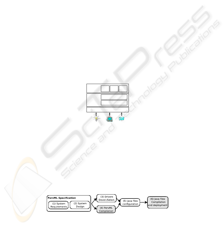
Interface
Layer
Logical
Layer
Services Layer
WAP
View
Voice
View
Communications Layer
HTML
View
Drivers Layer
Fig.1. Framework architecture.
The implementation framework, which is introduced in [4], has been build on top
of the OSGi middleware. It provides similar abstract classes to the PervML concep-
tual primitives (Service, Trigger, Interaction, etc.) in order to facilitate the translation
process. Fig. 1 shows the overall framework architecture. This architecture has been
designed with the aim of providing facilities for integrating several technologies (EIB
networks, web services, etc.) and for supporting multiple user interfaces.
Fig.2. Steps for applying the proposed.
14

Fig. 2 shows the steps that should follow a development team. The grey bubbles are
automatically carried out. Next we briefly introduce each step:
1. The system analyst specifies the system requirements using the service concep-
tual primitive. The system analyst uses three kind of PervML models in order to
describe (1) the kind of services available on the system, (2) the number of ser-
vices which are availables in every location and (3) how they interact when some
condition holds.
2. The system architect selects the kind and number of devices or software sys-
tems that are more suitable in order to provide the services specified by the analyst.
The selection could have into account economical reasons or constraints in the sys-
tem physical environment. The system architect uses other three PervML models
for describing (1) the kind of devices or software systems that are used for provid-
ing the system services, (2) the specific elements that are going to implement every
service and (3) the actions that the device or software systems must carry out for
providing every service operation.
3. An OSGi developer implements the drivers for managing the devices or soft-
ware systems which were selected by the system architect. These drivers provides
access from the OSGi-based framework to the devices or external software sys-
tems. They must be developed by hand, since they deal with technology-dependent
issues. If any device or external software system was used in a previous system, the
same driver can be reused.
4. The transformation engine is applied to the PervML specification. Many Java
files and other resources (Manifest files, etc.) are automatically generated as a result
of this action.
5. The Java files are configured in order to use the selected drivers. This configu-
ration only implies to set up the drivers identifiers.
6. Finally, the generated files are compiled, packaged into bundles (JAR files) and
deployed in the OSGi server with the implementation framework and the drivers.
The proposed method is focused on the development of the software system that is
part of the pervasive system. The physical installation of devices, networks, etc. is out
of the scope of this work.
3 Case of Study: The Pervasive Meetings Room
The case of study which is shown in this paper aims to improve the functionality pro-
vided by a meeting room. This section briefly describes the functional requirements that
must be fulfilled by the pervasive system.
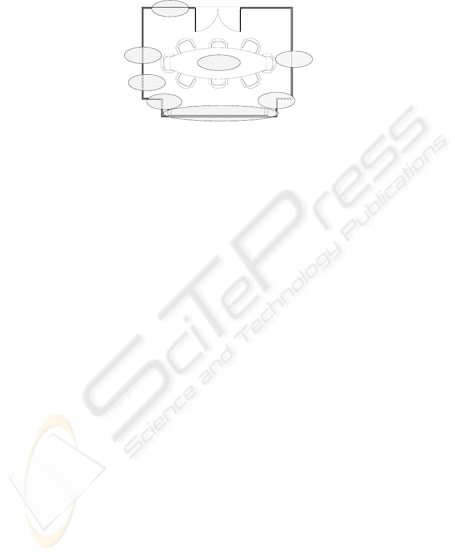
The meeting room, which is shown in Fig. 3 provides two kind of lighting services:
the main lighting service, which covers all the room, and an specific service for lighting
a projector screen. Users must be able to switch these lighting services manually using
some kind of device. When anybody is near the screen, the intensity of the specific
lighting must be decreased in order to provide a better visibility. Moreover, a security
system must record what happens in the room if anybody is there when the security is
activated.
15
208mm0mm0mm
149mm
0mm
149mm
208mm0mm
Global Lighting
Screen Lighting
Player
Screen Presence
Detection
Global Presence
Detection
Record
Global Lighting
Activation
Screen Lighting
Activation
Fig.3. The meeting room plan.
4 System Description using PervML
Perv-ML is a language designed with the aim of providing to the pervasive system de-
velopers with a set of constructs that allow to precisely describe the pervasive system.
Perv-ML promotes the separation of roles where developers can be categorized as an-
alysts and architects. Systems analysts capture system requirements and describe the
pervasive system at a high level of abstraction using the service metaphor as the main
conceptual primitive. System architects specify what devices and/or existing software
systems realize system services. Next we give a more detailed description of the lan-
guage and how it is applied to the meeting room case of study.
4.1 The Analyst View: Specifying System Requirements
The goal of the pervasive system analyst is to capture the system requirements using
high level of abstraction primitives. PervML considers that a pervasive system provides
services to the users in an environment. In the PervML Analyst View, the analyst de-
scribes the pervasive system using the service metaphor as the main conceptual primi-
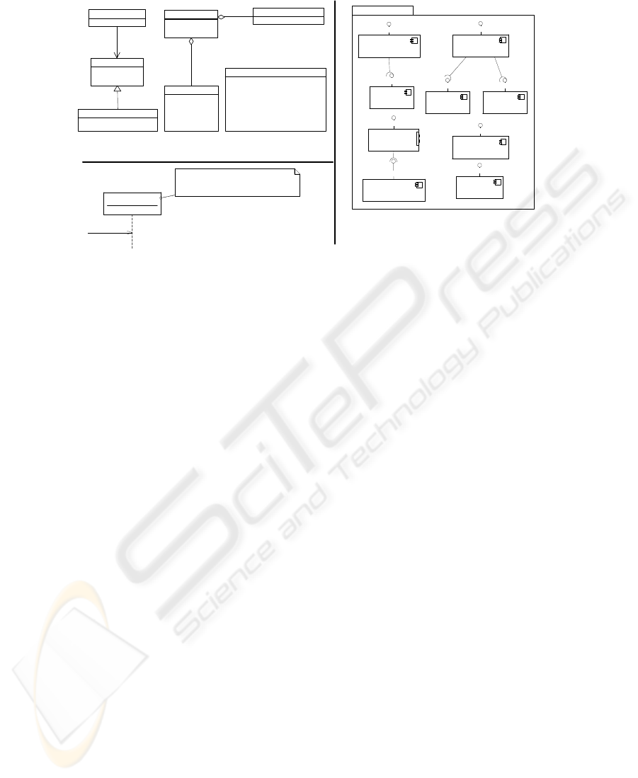
tive. This view is composed by three models which are shown in Fig. 4.
The system analyst uses the Services Model for describing the kinds of services that
are provided in the pervasive system. The diagram which represents the Services Model
in Fig. 4 shows that the meeting room provides services for controlling the lightings, for
detecting presence, for recording video, etc. Additionally to the information shown in
Fig. 4, the description of a kind of service includes (1) pre and post conditions (which
are expressed using the Object Constraint Language (OCL)) for every operation, (2)
a Protocol State Machine which indicates the operations that can be invoked in a
specific moment, and (2) triggers which allow specifying the proactive behaviour of
the services.
The system analyst uses the Structural Model to indicate the instances of every
kind of service which are provided by the system. The services are represented as com-
ponents whereas the kind of service that they provide is depicted as an interface (using
the lollipop notation). Dependency relationships between components can be included
in order to specify that one component uses the functionality provided by another. In
16
+presenceDetected() : Boolean
PresenceDetection
+switchOn()
+switchOff()
+isLighting() : Boolean
Lighting
+isActivated() : Boolean
Activation
+setIntensity(entrada Intensity : int)
+getIntensity() : int
GradualLighting
+on() : void
+off() : void
+play() : void
+forward() : void
+rewind() : void
+stop() : void
+currentMode() : String
+setMediaSource(entrada mediaFile : String)
+currentMediaSource() : String
Player
+enable()
+disable()
+isEnabled() : Boolean
Security
+on() : void
+off() : void
+record() : void
+stop() : void
+currentMode() : String
+savedMedia() : String
Record
0..*
1..*
0..1
1..*
1
*
ScreenGradualLighting
GradualLighting
ScreenActivation
Activation
MultimediaPlayer
Player
NearScreenPresence
PresenceDetector
GlobalPresence
PresenceDetector
SecurityManagement
Security
Recorder
Record
MainLightingActivation
Activation
MainLighting
Lighting
/MeetingsRoom
Services Model
Structural Model
ScreenGradualLighting
NearScreenPresence.presenceDetected() = true and
ScreenGradualLighting.isLighitng() = true and
ScreenGradualLighting.getIntensity() > 70
setIntensity(70)
Interaction Model
Fig.4. The models that are used in the Analyst View.
our case, the SecurityManagement component that provides the Security kind of
service uses the functionality provided by the GlobalPresence and the Recorder
components.
The system analyst uses the Interaction Model for describing the actions that are
carried out in the system when some condition holds. This model is composed by a
set of UML 2.0 sequence diagrams. Fig. 4 shows the interaction that is in charge of
decreasing the light intensity when anybody is near the screen.
4.2 The Architect View: Designing the System
In order to provide a complete specification, an abstract description is not enough. The
devices and software systems that conform the pervasive systems are key elements,
since they are the final suppliers of the system functionality. We call binding providers
to these elements (devices and software systems), because they bind the pervasive sys-
tem with its physical or logical environment.
In the PervML Architect View, the architect specifies what kind of devices and
software systems are used in the system, which elements implement every service and
how these elements provide the service. The system architect decisions must take into
account issues like the project budget, device availability, the physical environment
structure, etc.
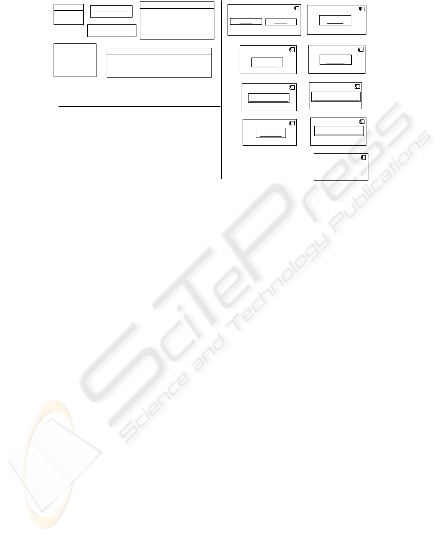
The system architect uses the Binding Providers Model to describe the different
kind of devices or software system that are used in the pervasive system. Fig. 5 shows
the Binding Providers Model for our meeting room. For instance, the diagram specifies
that the PresenceDetector sensor provides an operation which returns the probability
that anybody is detected in a location. It is important to note that this model describes
the functionality provided by a kind of device or software system, but it is not tighted
17
+off() : void
+on() : void
+isOn() : bool
Lamp
+probabilityOfPresence() : int
PresenceDetector
+decrease() : void
+isOn() : bool
+off() : void
+on() : void
+increase() : void
+currentPos() : int
GradualLamp
+activated() : bool
Switch
+moveToSecond(entrada secondi : int) : void
+currentSecond() : int
+pause() : void
+switchOff() : void
+playFile(entrada fileURL : string, ) : void
+getState() : int
+length() : int
Projector
+saveTo(entrada fileName : string, entrada mode : string, ) : void
+getMotionDetection() : bool
+getState() : string
+record() : void
+stop() : void
MotionDetectionCamera
ScreenActivation
«sensor»
S1 : Switch
MainLighting
«actuator»
L3 : Lamp
ScreenGradualLighting
Objeto1
Objeto2
MainLightingActivation
«sensor»
S2 : Switch
GlobalPresence
«sensor»
M1 : MotionDetectionCamera
SecurityManagement
NearcScreenPresence
«sensor»
PD1 : PresenceDetector
Recorder
«sensor»
M1 : MotionDetectionCamera
MultimediaPlayer
«actuator»
P1 : Projector
Binding Providers
Model
Component Functional
Specification
Component Structural
Specification
bool presenceDetected():
returnValue = _PD1_.probabilityOfPresence() > 80;
Fig.5. The models that are used in the Architect View.
to any specific item. For instance, the Lamp described in the model could be finally
implemented as an EIB lamp or a X10 lamp or a lamp in any other control network.
The system architect uses the Component Structure Specification to assign de-
vices and software systems to every system component. Note that the same binding
provider can be used for implementing several services. For instance, the MotionDetec-
tionCamera is used both for implementing a PresenceDetection service and a Recorder
service.
The system architect uses the Component Functional Specification to specify the
actions that are executed when an operation of a service is invoked. These actions are
specified using the Action Semantics Language (ASL) of UML. Every operation pro-
vided for every component must have associated a functional specification. Fig. 5 shows
the actions that are executed when the presenceDetectedoperation of the Global-
Presence is invoked. The specification determines the return value comparing the prob-
ability returned by the presence detector device (called PD1) with a threshold value that
is fixed to 80%.
5 Implementation Details
In this section we provide some details about the finally produced pervasive system. Fig.
6 shows the overall network structure. The central server is a Pentium IV barebone with
512Mb RAM and connectivity by ethernet, 802.g and serial port. The barebone runs a
Windows XP Professional Edition. We have selected the Prosyst Embedded Server 5.2
as the OSGi implementation.
In order to support the control devices (lights, switches and presence detector), an
EIB network has been deployed. The pervasive system accesses to this network by
18
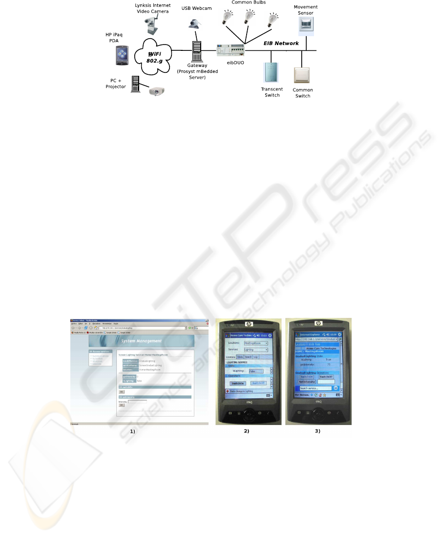
Fig.6. Network structure of the meeting room system.
means of the EIB bundle provided by Prosyst. The barebone is physically connected to
the network by the serial port.
The camera with motion detection capabilities is a Linksys Wireless-G Internet
Video Camera. This camera provides the video as an ASF stream. Moreover, it can be
configured to send an email when it detects some kind of motion. We have developed
an OSGi driver for integrating in our system these features.
Finally, the projector has been implemented using a common projector attached to
a Pentium II. This computer runs a Windows XP Home with a Windows Media Player in
full screen mode. The projector computer hosts a program which provides web services
for controlling the Media Player. We have developed an OSGi driver for accessing these
web services from the pervasive system.
Fig.7. The three user interfaces for managing the pervasive system.
Users interact with the system using several kind of devices, so multiple user inter-
faces must be provided. Currently, we provide three different user interfaces, which are
shown in Fig. 7 : (1) A Web interface for desktop browsers (Fig. 7, 1), (2) a native
PDA application (Fig. 7, 2), and (3) a Web interface for PDA browsers (Fig. 7, 3).
19

6 Conclusions
This work introduces an application of the Model Driven Development approach to the
field of pervasive systems. Following the proposed method, the specification of the sys-
tem functionality is independent of the devices selected for implementing the system.
Moreover, all the specification is independent of manufacturer issues. The manufac-
turer dependent details are isolated in the drivers layer. These characteristics provide a
high degree of manufacturer an technology independence: we can change all the imple-
mentation technologies just replacing the drivers, but from the user point of view the
functionality provided by the pervasive system still remains the same.
As a future work, we plan to extend the expressiveness of PervML and the features
of the implementation framework in order to give suppport to (1) the specification of
richer user interfaces, maybe applying the SmartTemplates approach [5] and/or using
a language for describing user interfaces like UsiXML [6], and (2) the specification as
first order entities of context-awareness characteristics and their implementation using
a framework like the proposed in [7].
References
1. Object Management Group: Model Driven Architecture Guide (2003)
2. Greenfield, J., Short, K., Cook, S., Kent, S.: Software Factories. Wiley Publising Inc. (2004)
3. Mu
˜
noz, J., Pelechano, V.: Building a Software Factory for Pervasive Systems Development.
In: CAiSE 2005, Porto, Portugal, June 13-17. Volume 3520 of LNCS. (2005) 329–343
4. Mu
˜
noz, J., Pelechano, V.: Applying Software Factories to Pervasive Systems: A Platform
Specific Framework. In: 8th International Conference on Enterprise Information Systems
(ICEIS 2006), Paphos (Cyprus) (2006)
5. Nichols, J., Myers, B.A., Litwack, K.: Improving Automatic Interface Generation with Smart
Templates. In: Intelligent User Interfaces (IUI) 2004, Funchal, Portugal (2004) 286–288
6. Limbourg, Q., Vanderdonckt, J.: Usixml: A User Interface Description Language Supporting
Multiple Levels Of Independence. In: Engineering Advanced Web Applications. Rinton Press
(2004) 325–338
7. Rossi, G., Gordillo, S., Fortier, A.: Seamless Engineering of Location-Aware Services. In:
On the Move to Meaningful Internet Systems 2005: OTM Workshops. Volume 3762 / 2005 of
LNCS. (2005) p. 176
20
