
Model Checking Suspendible Business Processes via
Statechart Diagrams and CSP
W. L. Yeung
1
, K. R. P. H. Leung
2
, Ji Wang
3
and Wei Dong
3
1
Lingnan University, Hong Kong
2
Hong Kong Institute of Vocational Education, Hong Kong
3
National Laboratory for Parallel & Distributed Processing, Changsha, Hunan, P.R. China
Abstract. When using statechart diagrams, the history mechanism can be use-
ful for modelling the suspension of a “normal” business process upon certain
“abnormal” events together with the subsequent resumption, as illustrated by the
examples in this paper. However, previous approaches to model checking state-
chart diagrams often ignore the history mechanism. We enhanced such a previous
approach based on Communicating Sequential Processes (CSP) and developed a
support tool for it.
1 Introduction
An essential task of modelling business activities is to identify the different types of
business transactions and the order in which they are conducted. For this there are two
inter-related modelling concepts. The first one is an object, which reflects how business
transactions are related to and distinguished from each other in an information system,
e.g. two borrowing transactions conducted in a library may differ in the book objects
being borrowed; a borrowing transaction is related to a returning transaction if they are
applied to the same book object. The second modelling concept is a process, which
is the order in which related transactions are carried out against/by a particular object
throughout its lifetime, e.g. a library membership object must first be created and then
maybe renewed a number of times before it is finally cancelled.
Process modelling has always been a challenging task. Poorly modelled processes
lead ultimately to information systems that handle business transactions incorrectly, and
hence to inaccurate information for managers. The problem is elevated to a larger scale
in enterprise information systems which involve unprecedented numbers of objects and
processes covering every major aspect of business nowadays.
Much research has been carried out on proposing, refining, extending, and integrat-
ing languages and notations for specifying processes, with the aim to ensure correctness
and make the task more efficient and manageable. The Unified Modelling Language
(UML) [1] settles with statechart diagrams, which is an adaptation of Harel’s state-
charts [2]. UML also includes a kind of diagrams known as activity diagrams which
are mainly used for modelling workflows but may also provide an alternative view of
processes. This paper is, however, only concerned with statechart diagrams.
L. Yeung W., R. P. H. Leung K., Wang J. and Dong W. (2006).
Model Checking Suspendible Business Processes via Statechart Diagrams and CSP.
In Proceedings of the 4th International Workshop on Modelling, Simulation, Verification and Validation of Enterprise Information Systems, pages 97-107
DOI: 10.5220/0002476600970107
Copyright
c
SciTePress

A statechart diagram represents a process in terms of states and transitions; transi-
tions among states are triggered by events that correspond to occurrences of business
transactions. A process represented in such a way is traditionally called a finite state ma-
chine (FSM). Compared with the traditional representation of FSM’s (ie. state transition
diagrams), statechart diagrams are incorporated with features such as composite states
and concurrent states that, on one hand, facilitate the modelling of complex processes
in a more succinct and manageable manner while, on the other hand, present new chal-
lenges for the verification task due to a much richer semantics.
Formal methods are widely recognised as a useful means of increasing software
reliability. The formal verification of statechart diagrams has been an active research
topic ever since UML was proposed. The syntax and semantics of statechart diagrams
have been formalised in various ways with tools developed for supporting automated
verification through model checking.
The result of our research presented in this paper enhances a previous approach
to formalising and model checking statechart diagrams [3, 4]. The approach is based
on a mapping of statechart diagrams into the formalism of Communicating Sequential
Processes (CSP) [5,6] together the associated FDR2 model checking tool [7]. This
approach, together with many others (e.g. [8–10]), do not, however, support history
states, which are often useful in modelling business activities that involve suspension.
The main enhancement presented here is the support of history states for modelling
suspendible business processes.
The next section briefly outlines the previous approach on which this work is based.
Section 3 discusses modelling of suspendible business processes in statechart diagrams.
Section 4 explains the representation of suspendible processes in CSP via a mapping
from statechart diagrams. Section 5 introduces some software tools that support the
application of model checking. Section 6 provides a conclusion and some discussion.
2 A CSP Approach to Formalising Statechart Diagrams
In this section, an approach to formalising statechart diagrams originally proposed by
Ng and Butler [3] and subsequently improved by Yeung et al [4] is briefly reviewed.
The reader is referred to [3,4] for details.
2.1 The Language of CSP
In the language of CSP, a process is described in terms of the possible interactions it
can have with its environment, which may be thought of as another process or set of
processes. Interactions are described in terms of instantaneous atomic synchronisations,
or events. A process can be considered as a “black box” with an interface containing a
number of events through which it interacts with other processes. The set of all events
in the interface of a process P, written αP, is called its alphabet. It is important to
note that interface events are intended as synchronisations between the participating
processes and not as autonomous actions under the control of a single process.
The following paragraphs briefly introduce the CSP operators used in this paper. A
comprehensive description of the language is found in [5,6]. The language of CSP used
98

in this paper is defined by the following pseudo Backus-Naur form definition:
P ::= Stop
a → P
P 2 P
Skip
P; P
P
k
A
P
P \ A
where Σ is the set of all possible events, a ranges over Σ, and A ⊆ Σ.
Let a and b be events and P, Q, and R be CSP processes. The process Stop is the
deadlocked process, unable to engage in any events or make any progress. The prefix
process a → P is ready to engage in event a (and in no other event). It will continue
to wait until its environment is also ready to perform a, at which point synchronisation
on this event will occur. Once the event is performed, the subsequent behaviour of
a → P will be that of process P. Given two processes P and Q, an external choice
P 2 Q is initially ready to engage in events that either P or Q is ready to engage
in. The first event performed resolves the choice in favour of the component that was
able to perform it, and the subsequent behaviour is given by this component. Skip is
the process that does nothing but terminates successfully. In the sequential composition
P; Q, the combined process first behaves as P and Q becomes active immediately after
the successful termination of P. P
k
A
Q is the parallel composition of P and Q in which
the two processes must synchronise on events in the set A. For instance,
(a → P 2 b → Q)
k
{a}
(a → R) = a → P
k
{a}
R
Finally, in P \ A, P’s ability to synchronise with the environment on any event a ∈ A is
disabled, with all such events taking place internally (hidden) as soon as they are ready.
RESERVED
RENEWED
HELD
UNRENEWED
SHELVED
return
reserve
renew
reserve
borrow
return
reserve
borrow return
HELD b= borrow → UNRENEWED
RESERVED b= return → HELD
RENEWED b= return → SHELVED 2 reserve → RESERVED
UNRENEWED b= return → SHELVED 2 renew → RENEWED
2 reserve → RESERVED
SHELVED b= borrow → UNRENEWED 2 reserve → HELD
BOOK b= SHELVED
Fig.1. Statechart diagram for a book object.
2.2 UML Statechart Diagrams
Figure 1 shows a statechart diagram for a book object in a library circulation record
system. For now, assume that there are only four types of transactions, namely, borrow,
return, renew, and reserve, with corresponding events as seen in the diagram. The reader
may notice the following properties about the order of events from the diagram:
1. A borrowed book may be renewed at most once.
99
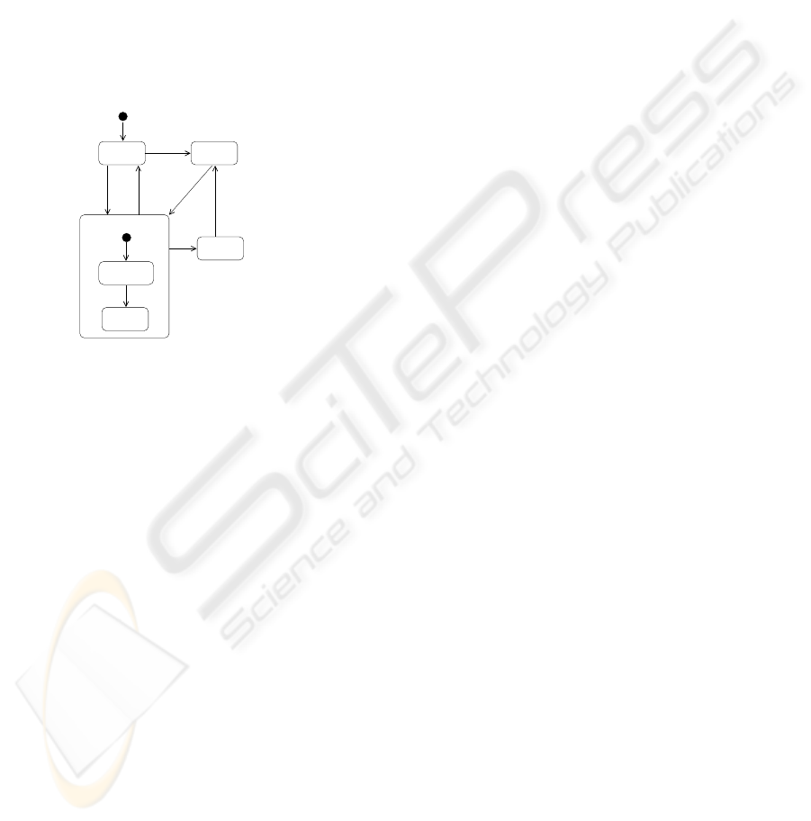
2. Once reserved, a borrowed book can no longer be renewed.
3. Once a book is reserved, it cannot be reserved again until after it has been borrowed.
4. A book on shelf can also be reserved (once) before it is borrowed.
Figure 1 also shows the CSP representation of the same process. The overall process
is defined in CSP as BOOK, which is in turn defined by a set of mutual-recursively
defined CSP processes, each of which corresponds to an individual state in the state-
chart diagram and represents the behaviour of the book object starting from that par-
ticular state. For instance, since SHELVED is the initial state, the overall behaviour
of a book (ie. BOOK) is defined by its behaviour starting from the SHELVED state
(ie. SHELVED).
UNRENEWED
RENEWED
SHELVED
HELD
RESERVED
BORROWED
renew
reserve
returnborrow
return
borrow
reserve
HELD b= borrow → BORROWED (1)
RESERVED b= return → HELD
RENEWED b= return → SHELVED 2 reserve → RESERVED
UNRENEWED b= return → SHELVED 2 renew → RENEWED
2 reserve → RESERVED
BORROWED b= UNRENEWED (2)
SHELVED b= borrow → BORROWED 2 reserve → HELD(3)
BOOK b= SHELVED
Fig.2. Statechart diagram featuring a composite state for a book object.
Figure 2 shows an alternative statechart diagram for the book object, together with
a corresponding CSP representation. The new diagram takes advantage of using a com-
posite state to represent exactly the same process in a slightly more compact manner.
The CSP representation has also been revised, with a new process BORROWED and
the definitions of HELD and SHELVED changed, to reflect the new diagram’s struc-
ture. As an assurance that the new and old diagrams both represent the same process,
substituting (2) into (1) and (3) gives the original CSP representation.
2.3 Mapping Statechart Diagrams into CSP
The CSP processes defined in Figures 1 and 2 can be systematically derived from the
corresponding statechart diagrams through a set of mapping functions. Given a finite
state machine M represented in a statechart diagram, we can define a function
H
M
: M
s
7→ CSP
where M
s
is the set of states of machine M. Given a state X ∈ M
s
, H
M
(X) is the CSP
process that represents the (subsequent) behaviour of machine M starting at state X.
100

The complete definition of H
M
can be found in [3, 4]. Here, as an example, let M
be the FSM represented by the statechart diagram in Figure 2, we have
H
M
(HELD) b= borrow → H
M
(BORROWED)
H
M
(RESERVED) b= return → H
M
(HELD)
H
M
(RENEWED) b= return → H
M
(SHELVED) 2 reserve → H
M
(RESERVED)
H
M
(UNRENEWED) b= return → H
M
(SHELVED) 2 renew → H
M
(RENEWED)
2 reserve → H
M
(RESERVED)
H
M
(BORROWED) b= H
M
(UNRENEWED)
H
M
(SHELVED) b= borrow → H
M
(BORROWED) 2 reserve → H
M
(HELD)
where M
s
= {SHELVED, BORROWED, UNRENEWED, RENEWED, RESERVED, HELD}.
Since SHELVED is the initial of the entire FSM, H
M
(SHELVED) as defined above rep-
resents the process of a book object, which is equivalent to the BOOK process defined
in Figure 2.
The mapping functions as defined in [3, 4] support a number of major statechart fea-
tures including composite states, entry and exit actions, do-activities, inter-level transi-
tions, and choice states.
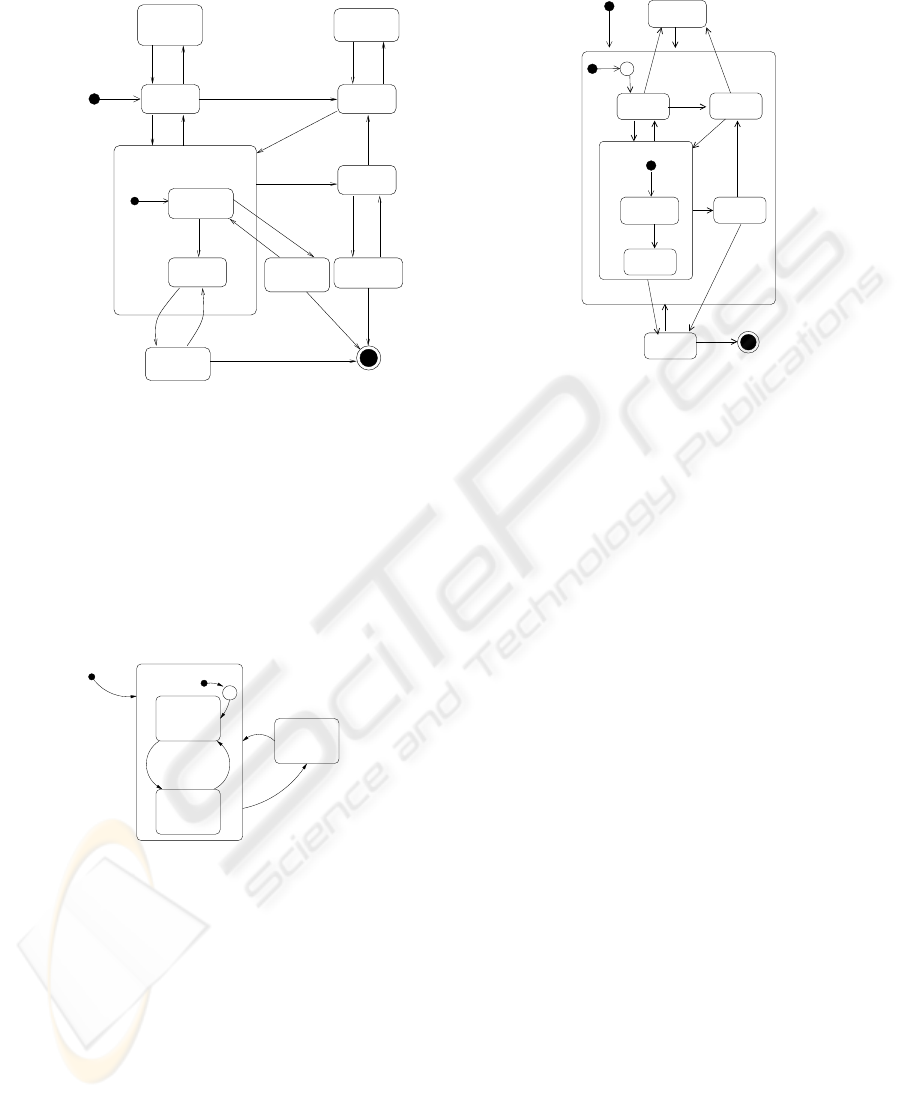
3 Suspendible Business Processes
Figure 3a shows yet another statechart diagram for the book object. The new diagram
represents a process involving five additional types of transactions, namely, suspend,
resume, lose, recover, and write-off. The library may suspend a book from circulation
(for maintenance purposes) when a book is either being SHELVED or HELD and sub-
sequently resume it to its last state when suspended. On the other hand, a book on loan
could be reported as lost by the borrower and be effectively suspended from circulation.
If a lost book is subsequently reported as recovered, it will be resumed to the last state
when reported as lost. A lost book may never be recovered and eventually written off.
Figure 3b shows an alternative statechart diagram for the suspendible book process.
The new diagram takes advantage of using a deep history state (
H
∗
)to represent the
same suspendible process in a visually more compact manner. Keeping a (deep) his-
tory of the “normal” process represented by the NORMAL composite state allows the
number of “suspended” states (SUSPENDED FROM SHELVED/HELD, LOST FROM
UNRENEWED/RENEWED/RESERVED) to be reduced from five to two
(SUSPENDED and LOST) with a corresponding reduction in the number of resum-
ing/recovering transitions. Observe that the NORMAL state is only entered through its
history. While this is not compulsory in statechart diagrams, we shall take advantage of
such cases in deriving the CSP representation as explained in the following section.
4 Modelling Suspendible Processes in CSP
To help explain the modelling of suspendible processes in CSP, we first consider a sim-
plified version of the book object. Figure 4 shows a statechart diagram for the book
101
LOST FROM
SUSPENDED
LOST FROM
HELD
SHELVED
RESERVED
LOST FROM
SUSPENDED
RENEWED
UNRENEWED
BORROWED
suspend
return
borrow
reserve
write off
lose
recover
write off
recoverlose
reserve
suspend
borrow return
renew
lose
recover
write off
resume
resume
FROM
SUELVED
FROM HELD
RENEWED
RESERVEDUNRENEWED
RESERVED
HELD
RENEWED
UNRENEWED
SUSPENDED
SHELVED
resume
lose
recover
NORMAL
suspend
suspend
reserve
reserve
return
BORROWED
borrow
renew
return
borrow
lose
write off
(b)
LOST
H
*
Fig.3. Statechart diagrams for a suspendible book process.
object with only two “normal” states, SHELVED and BORROWED. Transitions be-
tween the two states are triggered by the borrow and return events. Apart from the
“normal” process, the book may be reported as lost at any time and then later recovered
again: a lose event would trigger a transition to the LOST state, from which a recover
event would trigger a transition back to the last active substate within the NORMAL
state through its history. Initially, the book is in the SHELVED state.
recover
H
*
SHELVED
BORROWED
borrow
NORMAL
return
LOST
lose
LOST(x) b= recover → if x = s then SHELVED
else BORROWED
BORROWED b= return → SHELVED 2 lose → LOST(b)
SHELVED b= borrow → BORROWED 2 lose → LOST(s)
NORMAL b= SHELVED
BOOK b= NORMAL
Fig.4. Statechart diagram for a simplified book object.
Figure 4 also shows the corresponding CSP representation. LOST involves a pa-
rameter in its definition. It responds to the recover event and then chooses between
BORROWED and SHELVED based on the value of the parameter, which is set by
BORROWED and SHELVED each time when they “call” LOST. While the mapping
in this example seems to work well and does maintain a correspondence between states
and processes, there is a serious drawback: history information about BORROWED and
SHELVED are not only handled by the corresponding CSP processes (BORROWED and
102

SHELVED) only, but also LOST which makes use of such history information—this can
be considered as contrary to the principle of information hiding [11]. The implication
is that any state with a transition directly or indirectly leading to the history indicator of
another (composite) state has to carry history information about the latter.
An alternative approach to handling history information that respects the principle
of information hiding is illustrated by the following CSP description of the same dia-
gram in Figure 4:
LOST =
r
.LOST → recover →
r
.NORMAL → LOST
BORROWED = return → SHELVED
2 lose →
r
.LOST →
r
.NORMAL → BORROWED
SHELVED = borrow → BORROWED
2 lose →
r
.LOST →
r
.NORMAL → SHELVED
NORMAL = SHELVED
BOOK =
LOST
k
{
r
.LOST,
r
.NORMAL}
NORMAL
\ {
r
.LOST,
r
.NORMAL}
There are two concurrent processes, LOST and NORMAL, and the behaviour of the
book is described by the parallel composition of these two processes. The two con-
current processes synchronise with each other on two special events,
r
.LOST and
r
.NORMAL, which correspond to transitions to the LOST and NORMAL states, re-
spectively. For instance, after an recover event, LOST is ready for a
r
.NORMAL event,
which corresponds to a transition to the NORMAL state. Since the transition is meant
to take place automatically following the trigger event, the
r
.NORMAL event, together
with the
r
.LOST, are designated as internal and hidden from the environment using
the “\” operator.
The definition of a set of functions based on [3,4] for mapping statechart diagrams
with history states into CSP can be found in [12], with the following restrictions on the
use of history states:
1. Incoming transitions do not “penetrate” inside a history-bearing composite state—
they stop at the boundary. In other words, a history-bearing composite state must
always be entered through its history.
2. A history-bearing composite state remembers its last active substate at any level of
its enclosure, i.e. deep history.
3. A history-bearing composite state may not contain any other history-bearing com-
posite states at any level of its enclosure, ie. no nested history.
Furthermore, our mapping does not support concurrent states, but it does support
entry and exit actions, final states, and inter-level transitions.
The above restrictions on the use of history-bearing composite states render them
behaviourally analogous to coroutines: an initial transition to a history-bearing compos-
ite state corresponds to a call to a coroutine; transitions among substates of the history-
bearing composite state correspond to the coroutine’s internal state changes; transitions
out of the history-bearing composite state correspond to suspending the coroutine and
transferring control away to other coroutines or the main program; incoming transitions
resume the coroutine.
103

In this paper, a suspendible business process is considered as having a “normal” life
with some “normal” events, together with some “abnormal” events that could suspend
the normal life temporarily. The restrictions on the use of history is least severe where
the “normal” life is always resumed at the point of last suspension as in our book ex-
ample. In those cases where the “normal” life is not always resumed at the point of
last suspension, restriction (1) would undermine the use of history. For instance, in the
book example, if a suspended book may also be replaced (apart from being resumed)
and assume that a replaced book is always returned to the shelf, we may modify the stat-
echart diagram in Figure 3b by adding a transition from SUSPENDED to SHELVED,
triggered by a replace event. However, this violates restriction (1). To get round this,
one has to give up (or reduce) the use of history and resort to the less compact style
exemplified in Figure 3a.
channel borrow, lose, recover, renew, reserve, return, suspend, writeoff
datatype States = BOOKTop’ | BOOKTop | SUSPENDED | LOST | FINAL | NORMAL |
SHELVED | HELD | RESERVED | BORROWED | UNRENEWED | RENEWED
subtype Process = BOOKTop | NORMAL
subtype Rstates = NORMAL | SUSPENDED | LOST
subtype SUSPENDED
s = NORMAL subtype LOST s = NORMAL
subtype NORMAL
s = LOST | SUSPENDED
channel Resume: Rstates.Rstates
St(BOOKTop’) = Resume.SUSPENDED?x:SUSPENDED
s -> St(SUSPENDED) [] Resume.LOST?x:LOST s -> St(LOST)
St(BOOKTop) = St(BOOKTop’)
St(NORMAL) = St(SHELVED)
St(BORROWED) = St(UNRENEWED)
St(UNRENEWED) = renew -> St(RENEWED) [] reserve -> St(RESERVED) [] lose -> Resume.LOST!NORMAL ->
Resume.NORMAL?x:NORMAL
s -> St(UNRENEWED) [] return -> St(SHELVED)
St(RENEWED) = reserve -> St(RESERVED) [] lose -> Resume.LOST!NORMAL ->
Resume.NORMAL?x:NORMAL
s -> St(RENEWED) [] return -> St(SHELVED)
St(SHELVED) = suspend -> Resume.SUSPENDED!NORMAL -> Resume.NORMAL?x:NORMAL
s ->
St(SHELVED) [] reserve -> St(HELD) [] borrow -> St(BORROWED)
St(HELD) = suspend -> Resume.SUSPENDED!NORMAL -> Resume.NORMAL?x:NORMAL
s ->
St(HELD) [] borrow -> St(BORROWED)
St(RESERVED) = return -> St(HELD) [] lose -> Resume.LOST!NORMAL ->
Resume.NORMAL?x:NORMAL
s -> St(RESERVED)
St(SUSPENDED) = resume -> Resume.NORMAL!SUSPENDED -> St(BOOKTop’)
St(LOST) = recover -> Resume.NORMAL!LOST -> St(BOOKTop’) [] write
off -> St(FINAL)
St(FINAL) = STOP
BOOK = (St(BOOKTop) [|{|Resume|}|] St(NORMAL)) \ {|Resume|}
Fig.5. CSP
M
representation of the book process and a screenshot of FDR2.
5 Software Tools for Model Checking
The mapping functions defined in [12] have been implemented as a software tool for
supporting the model checking of suspendible processes represented in UML statechart
diagrams. Figure 6 shows how the tool interfaces with the Poseidon UML CASE tool
and the FDR2 model checker [7], which is the standard model checker for CSP. We
use Poseidon as a graphical tool for editing statechart diagrams. The software tool itself
is written as a set of XSLT templates which takes as input an XMI representation of
statechart diagrams from Poseidon and generates CSP
M
, a machine-readable represen-
tation of the CSP language for model checking with FDR2. Figure 5 shows the CSP
M
representation of the statechart diagram in Figure 3b as generated by the software tool.
6 Related Work
Von der Beeck [13] gave a survey of several variants of statecharts, prior to the arrival
of UML statechart diagrams. UML statechart diagrams have been formalised in nu-
104

Editing
diagram
XMI
script
CSP
M
script
Poseidon
XSLT
tool
FDR2
Model
Checking
Mapping
Statechart
Fig.6. Software tools for editing, mapping, and model checking statchart diagrams.
merous other formalisms such as pi-calculus [14], LOTOS [15], ASM [16]. Closest to
our work is the work by Ng and Butler [3] in which a formalisation of UML statechart
diagrams in CSP is presented in a style that is followed in this paper. Yeung et al [4] im-
proved this formalisation on inter-level transitions. Most of the previous formalisations
do not tackle history states. von der Beeck [17] gave a structural operational seman-
tics to statechart diagrams which does cover shallow/deep history states and composite
AND-states.
Well-known commercial model checkers for statecharts include STATEMATE [18].
Other statecharts model checkers include [19, 20]. We managed to obtain three publicly
available support tools and environments specifically for model checking UML state-
chart diagrams, namely, JACK [21], UMLAUT [8], and UMC [10]. None of these three
tools support the history mechanism. Other UML model checking tools found in the lit-
erature include vUML [22] and Rhapsody [23]. Roscoe [24] also developed a compiler
(translator) for translating a textual representation of statecharts into CSP for model
checking with FDR2 [7]. Finally, progress has been made in model checking UML
statechart diagrams with time [25].
7 Discussion and Conclusion
An approach to verifying suspendible business processes represented in statechart dia-
grams has been presented. It involves a mapping that translates a statechart diagram into
a CSP representation in a way that maintains a strong “structural” correspondence be-
tween the former and the latter. This helps relate any errors revealed by model checking
to the original statechart diagrams.
The use of parallel processes to model a state machine may lead to the well known
state explosion problem and indeed considerable care was taken to ensure that parallel
processes are tightly coupled by “
r
” events so that the state space is kept under control
during model checking. See [12] for the mapping in details.
The mapping assumes the use of history states under certain restrictions as stated
towards the end of section 4. These restrictions affect how we model business processes
involving suspension and resumption. One may consider these restrictions too much an
obstacle to modelling as one is bound to find cases and reasons for removing them.
We admit to such shortcomings but would like to note that, from our experience, mod-
elling a suspendible business process can often benefit partly from the restricted use
of history. Besides, liberal use of history could lead to complicated statechart diagrams
that are difficult to comprehend. On the other hand, the restrictions afford us the anal-
ogy between a history-bearing composite state and a coroutine which might actually
encourage someone not familiar with the former to use it with confidence in modelling.
105

Finally, the mapping functions used in defining the semantics are readily imple-
mentable and allows for a prototyping approach to the semantic definition, ie. we ex-
perimented with the software tool that implemented the mapping functions while devel-
oping and refining the mapping itself. Currently, we are still continuing to extend and
refine the mapping to cater for more features of statechart diagrams such as concurrent
states and actions.
Acknowledgements
The first author is supported by Research Grant DR05A1 from Lingnan University.
The third and fourth authors are supported by National Natural Science Foundation of
China Grants No. 60233020, 60303013. The authors would like to thank the anonymous
referees for their helpful comments and suggestions.
References
1. Object Management Group: OMG Unified Modeling Language Specification Version 1.5.
(2003)
2. Harel, D.: Statecharts: A visual formalism for complex systems. Science of Computer
Programming 8 (1987) 231–274
3. Ng, M.Y., Butler, M.: Towards Formalizing UML State Diagrams in CSP. In: Proc. 1st IEEE
International Conference on Software Engineering and Formal Methods. Lect. Notes Comp.
Sci., IEEE Computer Society (2003) 138–147
4. Yeung, W.L., Leung, K.R.P.H., Wang, J., Dong, W.: Improvements towards formalizing
UML state diagrams in CSP. In: Proc. 12th Asia Pacific Software Engineering Conference,
December, 2005, Taipei. (2005)
5. Hoare, C.A.R.: Communicating Sequential Processes. Prentice Hall (1985)
6. Roscoe, A.W.: The Theory and Practice of Concurrency. Prentice Hall (1998)
7. Formal Systems (Europe) Ltd.: Failures-Divergence Refinement: FDR2 User Manual. (2003)
8. Ho, W.M., Jquel, J.M., Guennec, A.L., Pennaneac’h, F.: UMLAUT: An extendible UML
transformation framework. In: Proc. Automated Software Engineering 1999. (1999) 275–
278
9. Schafer, T., Knapp, A., Merz, S.: Model checking UML state machines and collaborations.
Electronic Notes in Theoretical Computer Science 47 (2001) 1–13
10. Gnesi, S., Mazzanti, F.: On the fly model checking of communicating UML State Machines.
In: Proc. Second ACIS International Conference on Software Engineering Research Man-
agement and Applications (SERA2004), Los Angeles, USA, May, 2004. (2004)
11. Parnas, D.: On the criteria to be used in decomposing systems into modules. Comm. ACM
(1972)
12. Yeung, W.L.: Towards formalizing UML state diagrams with history in CSP. Technical
report, Lingnan University (2005) http://cptra.ln.edu.hk/ wlyeung/history.ps.
13. der Beeck, M.V.: A comparison of statecharts variants. In: Proc. Formal Techniques in Real
Time and Fault Tolerant Systems. Volume 863 of LNCS., Springer (1994) 128–148
14. Lam, V.S.W., Padget, J.: Formalization of UML statechart diagrams in the pi-calculus. In:
Proc. 13th Australian Software Engineering Conference. (2001) 213–223
15. Cheng, B., Campbell, L., Wang, E.: Enabling Automated Analysis Through the Formaliza-
tion of Object-Oriented Modeling Diagrams. In: Proceedings of IEEE International Confer-
ence on Dependable Systems and Networks, IEEE (2000) 305–314
106

16. B
¨
orger, E., Cavarra, A., Riccobene, E.: Modeling the dynamics of UML state machines.
In: Proc. Abstract State Machines: Theory and Applications (ASM2000). Volume 1912 of
LNCS., Springer-Verlag (2000) 223–241
17. von der Beeck, M.: Formalization of UML-Statecharts. In: UML 2001. Volume 2185 of
LNCS., Springer (2001) 406–421
18. Bienmulller, T., Damm, W., Wittke, H.: The STATEMATE verification environment - making
it real. In Emerson, E.A., Sistla, A.P., eds.: CAV 2000. Volume 1855 of Lecture Notes in
Computer Science., Springer (2000) 561–567
19. Mikk, E., Lakhnech, Y., Siegel, M., Holzmann, G.J.: Implementing statecharts in
PROMELA/SPIN. In: Proc. Second IEEE Workshop on Industrial Strength Formal Spec-
ification Techniques, IEEE (1998) 90–101
20. Pingree, P.J., Mikk, E.: The hivy tool set. In: CAV 2004. Volume 3114 of LNCS., Springer
(2004) 466–469
21. Gnesi, S., Latella, D., Massink, M.: Model checking UML statechart diagrams using JACK.
In: HASE ’99: The 4th IEEE International Symposium on High-Assurance Systems Engi-
neering, IEEE (1999) 46–55
22. Lilius, J., Paltor, I.P.: vUML: A Tool for Verifying UML Models. In: Proceedings of 14th
IEEE International Conference on Automated Software Engineering, IEEE Computer Soci-
ety (1999)
23. Schinz, I., Toben, T., Mrugalla, C., Westphal, B.: The Rhapsody UML Verification Environ-
ment. In: Proc. 2nd International Conference on Software Engineering and Formal Methods
(SEFM 2004), Bejing, China, IEEE (2004) 174–183
24. Roscoe, B.: Compiling statemate statecharts into CSP and verifying them using FDR -
abstract. http://web.comlab.ox.ac.uk/oucl/work/bill.roscoe/publications/94ab.ps (2003)
25. Bianco, V.D., Lavazza, L., Mauri, M.: Model checking UML specifications of real time
software. In: Proc. 8th IEEE International Conference on Engineering of Complex Computer
Systems (ICECCS’02), IEEE (2002) 203–212
107
