
ON IMPLEMENTING INTEROPERABLE AND FLEXIBLE
SOFTWARE EVOLUTION ACTIVITIES
M. Bouneffa, H.Basson, Y. Maweed
Laboratoire d’Informatique du Littoral, Univcersité du Littoral, Côte d’Opale,55 Rue Ferdinand Buisson, Calais, France
Keywords: Software evolution, graphs rewriting, GXL, change impact propagation, architecture recovery.
Abstract: In this paper we present an approach for assistance at software evolution based on an integrated model of
representation of the various software artifacts. This model founded on the typed and attributed graphs as
well as a representation of these graphs using GXL (eXtensible Graph Language) a language for structuring
hyperdocuments. The hyperdocuments GXL are used to facilitate the interoperability between tools
intended to represent and handle various aspects of the software evolution. We also use the graph rewriting
systems for a simple and flexible implementation of mechanisms required for reasoning by software
evolution management. Our approach has been applied to several applications; it is illustrated here on
change impact management of applications developed according to multi-tiered architecture Java J2EE and
the architecture recovery of these applications.
1 INTRODUCTION
Software evolution is a general activity including all
the processes aiming at changing the software to
meet new real world requirements. These
requirements represent the need to modernize the
software system as a consequence of the
technological or management evolutions or to
improve its functions or quality.
In general, the evolution activity follows five
major steps. The first one consists of the new
requirements specification while the second step
consists of understanding the software in order to
produce a real description or cartography of its
structure, functions and behaviour. The third step is
to simulate the change such as to estimate its effects
from different standpoints. The fourth step consists
of implementing the change and the last step aims at
the changed software testing and to draw up the
assessment and feedbacks about the targeted change
impact. All these steps deal with software artefacts
such as source codes, design schemas, architectural
or functional descriptions, etc.
Many works have dealt with software evolution;
most of them have focused on artefacts issued from
one stage of the software life cycle such as source
codes or database schemas (Rajlich, 1997)
(Gwizdala, 2003) (Korman, 1998) (Rashid, 2005)
(Bouneffa, 1999). However, the increasing size and
complexity of the current computing systems leads
inevitably to deal with software artefacts considered
at several abstraction views. Subsequently, the
software evolution management requires being able
to understand the software on both high and detailed
description levels. Moreover, the links between
these levels must be clearly defined. This will
provide the change management the mapping
between architectures components, implemented
functionalities and their source codes. Works
dealing with reverse engineering attempt to achieve
this goal by extracting several abstract views of the
software. These views are then used to facilitate the
software understanding before making any change.
So, different views of the software description
expressed by means of different kind of constructs
like class diagrams, data-flow graphs, star diagrams,
etc., have been proposed (Korman, 1998)(Griswold,
1990)(Murphy, 1997). The proposed representations
are generally used as intermediate representations
i.e. more abstract than source codes but less abstract
than architectures or design descriptions. The
reverse engineering uses generally the different
diagrams extracted by program analysis tools to
obtain more abstract software views like
architectures or functional decompositions of the
software in terms of subsystems. For this goal,
different techniques have been used. For instance, G.
253
Bouneffa M., Basson H. and Maweed Y. (2006).
ON IMPLEMENTING INTEROPERABLE AND FLEXIBLE SOFTWARE EVOLUTION ACTIVITIES.
In Proceedings of the Eighth International Conference on Enterprise Information Systems - ISAS, pages 253-260
DOI: 10.5220/0002453802530260
Copyright
c
SciTePress
Murphy (Murphy, 1997) introduces reflexive model
to extract the software design. This is based on the
integration of the human expert knowledge about the
system and constructs extracted from the source
code by analysis tools. Some work has considered
the architecture as a part of the source codes
(Aldrich, 2002)(Holder, 1999). The general
tendency of these works is to express the
deployment of an application by new syntactic
constructs enriching the present programming
languages. More recent works try to extract
architectures by means of evolutionary computing
approaches like genetic algorithms (Mitchell,
2002).
In general, the works dealing with the software
evolution have led to the development of tools
focusing on specific aspects of the software change.
However, the software evolution process is very
complex and has to deal with several aspects of
changed components, which requires various tools.
This situation leads us to develop a platform
intended to host a large family of software evolution
tools. The platform called Integrated Framework for
Sofwtare Evolution and Maintenance (IFSEM) has
been developed in order to perform various activities
and tasks concerning the software evolution in a
flexible and uniform manner. Many tools have been
developed within this platform including the change
impact analysis and propagation, the cartography of
legacy systems and the quality evaluation (Bouneffa,
1999) (Deruelle, 2001a) (Deruelle, 2001b) (Melab,
1999).
In this paper, we first describe the IFSEM
platform and its use and highlight its limits in terms
of the hosted tools interoperability and flexibility.
We propose then a new approach aiming to achieve
more flexibility and interoperability of the hosted
tools. This approach is based on the use of graph
rewriting systems (Ermel, 1999), for more
flexibility, and the standard Graph eXchange
Language (GXL), for better interoperability (Holt,
R., 2000).
The paper is composed as following: section 2
describes the IFSEM platform and its limits and
drawbacks. Section 3 describes the concepts of the
new approach, which are graphs, graph rewriting
systems and GXL. Section 4 is devoted to present
the structure of the new developed platform. In the
fifth and sixth sections we describe the use of the
new approach to develop two tools destined to the
architecture recovery of Java J2EE (Sun
Microsystems, 2002) applications from source codes
and the software change propagation and. Final
section is devoted to the paper conclusion and the
future directions of our work.
2 THE IFSEM PLATFORM
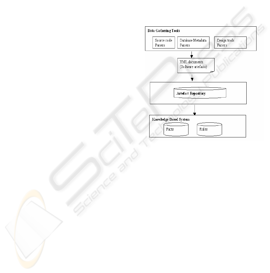
IFSEM is a platform dedicated to host software
evolution tools. It is composed of a core system
(Figure 1) including a set of data gathering tools, a
software artefact repository and a Knowledge-Based
System. The three major components are all
developed by means of Java classes making easier
their reusability.
Figure 1: The core of IFSEM.
The data gathering tools are a collection of Java
programs including source code parsers and other
programs for diagrams parsing produced by design
and analysis tools. The considered languages are
C/C++, Java, COBOL, HTML and CORBA-IDL
(Vinoski, 1997). There is also a Java bytecode
decompiler and some tools for information gathering
from database metaschemas. We have implemented
such tools for Oracle and ObjectStore (ObjectStore,
1998) DBMSs. The combination of the gathering
tools allows extracting the information from
applications developed using several programming
languages, DBMSs or middlewares. This
information is represented by XML documents
storing the artefacts following a software artefacts
model called SCSM (Software Component
Structural Model). The XML documents are then
stored in an object oriented database (ObjectStore,
1998) playing the role of software artefacts
repository. The knowledge-based system is built on
top of the JESS tool (Friedman-Hill, 1998), which is
ICEIS 2006 - INFORMATION SYSTEMS ANALYSIS AND SPECIFICATION
254

a Java clone of CLIPS (CLIPS, 2005) that is one of
the most known and used expert system generator.
The KBS provides facilities for writing rules
dedicated to software evolution. As illustration
example of a rule: If a method is deleted then all the
methods calling it are impacted by this deletion.
IFSEM has been experimented as a workbench
to implement four engineering tools that are: a
graphical software browser, a change impact
propagator, a source code profiler and the
cartography of legacy systems
.
2.1 Limits and Drawbacks of
IFSEM
The use of object-oriented concepts in our
experimentations appeared as a good way to build
reusable components and to enrich an existing
platform with new developed tools. However, it is
expensive to integrate tools that are not developed in
Java or using different artefact representation
models. There is also another fundamental problem
concerning the impedance mismatch. In fact, the
software artefacts are represented by three different
concepts: persistent objects, graph elements and
predicates. So, a same artefact may have three views
following the tool manipulating it. The KBS
represents the artefacts by predicates, the repository
stores them as persistent objects and algorithms
consider them as graph elements. The impedance
mismatch increases the complexity of the platform
and underlying tools and then decreases the
flexibility of implementing such tools. To achieve
more interoperability and flexibility, we decided to
redevelop the platform by means of an intensive use
of graph rewriting systems and GXL (Graph
eXchange Language) that is a standardized format
especially defined to improve interoperability of
software engineering tools. The resulting platform
has been used to develop three main tools that are: a
change propagation tool, a program refactoring tool
and an architecture recovery tool. We show further
the new platform and the implementation of the
change impact propagation and the architecture
recovery processes under this platform.
3 GRAPHS, GRAPH REWRITING
SYSTEMS AND GXL
The model we use to both represent and manage
software artefacts is based on typed and attributed
graphs where the nodes represent the different kind
of software artefacts and the edges the various
relationships relating them. The nodes and edges are
typed making it possible to produce different views
of the software following the considered types of
nodes and edges. For instance, one can consider only
classes and the inheritance relationship or functions
and the calling relationship, etc. In our model all the
granularity levels may be considered. So, it is
possible to deal with artefacts like statements and
symbols (fine grained) or files (coarse grained). The
same model is used to represent also architectural
artefacts like components, roles and ports, etc.
The graphs are represented by means of GXL
(Graph eXchange Language). GXL has been
defined and adopted by the software engineering
community as a standard format for graph exchange.
The goal of such a model is to improve the
interoperability of the software engineering tools
that represent the software by graphs. GXL is based
on XML. In fact, graphs are represented by XML
hyper-documents defining special tags to represent
nodes, edges, hierarchical graphs, etc. As the MOF
(Meta Object Facilities) (OMG, 2002) GXL defines
three abstract levels of models. The first level
corresponding to a meta-meta-model defines all the
predefined concepts of GXL including the definition
of graph, node and edge tags, etc. The second level
corresponding to a meta-model represents a graph
type or schema. In fact, the GXL graphs may be
typed. The third level is the graph itself as an
instantiation of the graph type.
Graph rewriting systems are based on the use of
graph rewriting rules (Ermel, 1999). These consist of
transforming a sub graph or a part of a graph by
another sub graph. Each rule may be expressed by
two graphs called LHS (Left hand side) and RHS
(Right hand Side). The execution of a rule in a given
graph H (called the host graph) consists of matching
the LHS of the rule with a sub graph L of H and then
replacing L by the RHS of the rule.
As example, the figure 2 shows a rule
implementing variable deletion in an object-oriented
program. In this figure, the nodes are labeled by
their types prefixed by an integer used to match the
nodes of the host graph with those of the LHS of the
rule. The LHS of the rule shows a class defining a
method that uses a variable. The method (2:method)
is called by another method (3:method). In the RHS
of the rule the node (4:variable) has been deleted and
a new node of type Impact has been created. This
means that when a variable is deleted all the
methods m using this variable are impacted and then
all the methods using m are also impacted.
ON IMPLEMENTING INTEROPERABLE AND FLEXIBLE SOFTWARE EVOLUTION ACTIVITIES
255
We describe presently the architecture of the new
platform.
4 THE ARCHITECTURE OF THE
NEW PLATFORM
To experiment the use of both GXL and graph
rewriting systems in implementing software
evolution activities, we develop a new platform. The
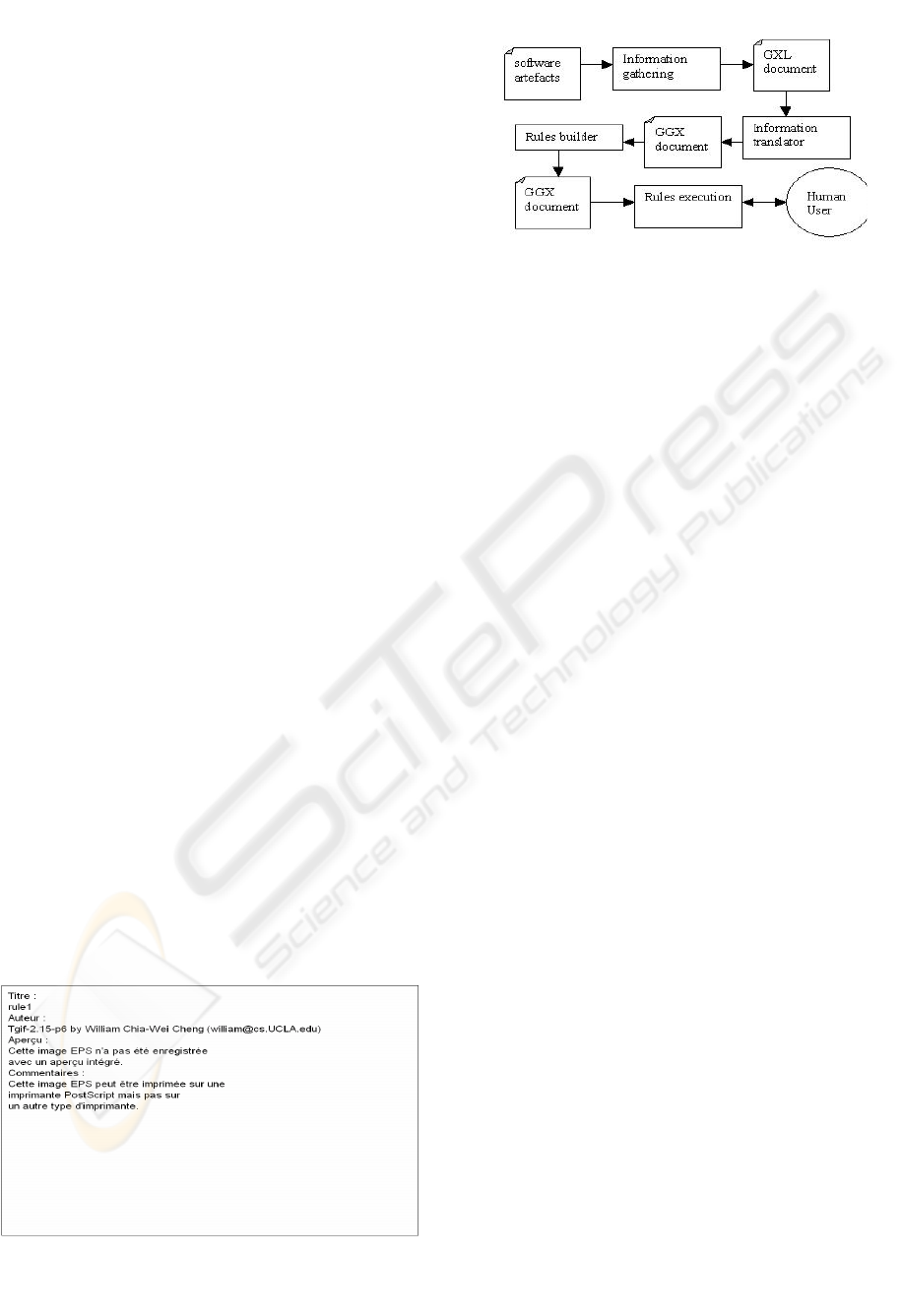
process hosted by the platform is implemented by
four interoperable tools that are: The information
gathering, the information translator, the rules
builder and the rules execution system (figure 3).
4.1 The Information Gathering
The information gathering is composed of a set of
parsers that produce GXL documents representing
the various software artefacts. Such artefacts may be
source codes, design documents, etc. We reused the
major part of the parsers yet developed in IFSEM
and add some new ones. For instance, we implement
a parser that transforms XMI documents to GXL by
means of XSLT (W3C, 2001). Such a parser allows
further analysis of design documents formalized by
the MOF (OMG, 2002) concepts. In fact, XMI
(XML Meta data Interchange) (OMG, 2005) is an
XML representation of the MOF documents.
4.2 The Information Translator
The information translator translates the GXL
documents into another XML format called GGX.
GGX is an XML-based format used by the graph
rewriting system AGG (Ermel, 1999) that is the
system we use to implement graph rewriting rules.
The information translator has been developed by
means of XSLT
.
4.3 The Rules Builder
This tool is a Java program producing the graph
rewriting rules implementing the software evolution
tasks. We develop a set of predefined rules that may
be viewed as rule packages. The user may then use
the rules builder in a visual way to choose the
needed packages to implement the evolution tasks
like change impact propagation or architecture
recovery. Nevertheless, the user may customise
these rules or define new ones by means of AGG in
order to implement its own strategy.
4.4 The Rules Execution System
The rules are executed by AGG that is a well-known
graph rewriting system. AGG allows also refinement
of predefined rules and analysis of these rules in
order to avoid inconsistencies, etc.
5 IMPLEMENTING
ARCHITECTURE RECOVERY
The architecture recovery process we implemented
consists of extracting the architecture of a Java J2EE
application. The input of the process is the source
code of the application and the output is an
architecture represented by means of an ADL
(Architecture Description Language) called ACME
(Garlan, D., 2000). Let us first make a description of
both the input and the output of the architecture
recovery process.
5.1 The Structure of a Java J2EE
Application
The Java J2EE platform provides facilities to build
and deploy distributed applications in a three-tiered
Figure 2: Example of a graph rewriting rule.
Figure 3: The structure of the new platform.
ICEIS 2006 - INFORMATION SYSTEMS ANALYSIS AND SPECIFICATION
256
architecture. The J2EE applications are mainly based
on the use of the Enterprise Java Beans (EJB)
framework. This is intended to support distributed,
Java-based, enterprise-level applications. It provides
an architecture that defines vendor-neutral interface
to information processing like persistence,
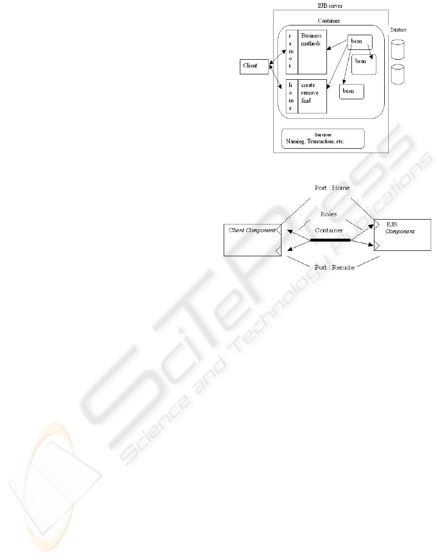
transactions and security. A typical Java J2EE
application is shown by the figure 3. The client may
be a Java application or a Web client like JSP pages.
The client requests services implemented by special
Java objects called beans. A running environment
called container manages the beans. The container
implements some internal and transparent system
tasks concerning the creation, removal, activation
and “passivation” of Java beans. It also provides
some services dealing with persistence, transactions
and naming. A bean implements two kinds of
interfaces: the remote and home interfaces. The
home interface concerns methods that create or
remove a bean when the remote interface provides
business methods.
5.2 ACME a Standard ADL
ACME is an architecture description language
combining the functionalities and constructs of a
large variety of other ADLs. It provides an
extensible generic structure to represent, generate
and analyse architecture descriptions. The main
constructs proposed by ACME are components,
connectors, systems and representations. The
components represent computation entities that are
described by properties and ports. The ports identify
a point of interaction between a component and its
environment. A connector specifies the interactions
between components. It is described by roles
specifying the behaviour of the interaction
participants (components). A system represents a
configuration of architecture. The system may be
viewed as a graph of components and connectors.
Components can be represented in a hierarchical
manner by means of representations. In fact, a
representation is a decomposition of high-level
components into a system representing it in terms of
low-level components and connectors. The vertical
relationship between a high level component and
those belonging to its representation is called
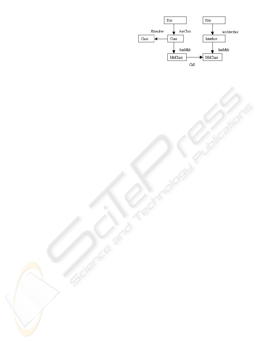
Representation-Map. As an example, the figure 4 is
an ACME graphical representation of an EJB
application. This representation is based on the
formalization of the EJB applications presented by
Garlan and Sousa (Sousa, 1999). The components
represent the client and the EJB and a connector
represents the container.
Figure 3: The structure of a Java J2EE application.
Figure 4: The ACME representation of a Java J2EE
application.
5.3 The Architecture Recovery
Rules
The architecture recovery process has been
implemented by means of two rule packages. The
first package called High Level Abstraction
Extracting Rules is used to transform the abstract
syntactic tree (AST) of a Java J2EE application into
a more abstract graph that has significance at the
architectural level. In fact, the java parser included
in the information gathering tool produces a GXL
document representing the AST of such an
application. The second package called Architecture
Mapping Rules contains rules transforming the
graphs produced by the rules of the first package
into a graph representing the architecture of the
application. Such a graph is a GXL document in
which node and edge types represent the concepts of
an ADL (ACME).
ON IMPLEMENTING INTEROPERABLE AND FLEXIBLE SOFTWARE EVOLUTION ACTIVITIES
257
5.3.1 High Level Abstraction Extracting
Rules
The high-level abstraction extracting rules are
partitioned into two kinds of rules: the relationships
extracting rules and the cleaning rules.
The relationships extracting rules are intended to
extract more abstract relationships from the AST of
a Java application. Such relationships may be
method calls, class inheritance, etc. In fact, the AST
does not contain explicit edges representing these
relationships and the rules transform paths of the
AST into a single and more abstract edge. For
instance, if the AST contains a path:
M1->B->St->M2 it means that a method M1
contains a block B that contains a statement St which
is a calling to another method M2, then this path is
transformed into M1->M2 where the arrow between
M1 and M2 represents an edge of Calling type.
The cleaning rules delete all the nodes and edges
that represent details with no significance at the
architectural level. So, after applying the high level
abstraction extracting rules and the cleaning rules
the resulting graph is a more abstract one containing
only nodes and edges that are significant at the
architectural level. The figure 5 shows an example
of such graph in the case of Java J2EE application.
In this figure, only Methods, Classes, Interfaces and
File are represented.
5.3.2 The Architecture Mapping Rules
These rules implement mappings of Java source
code concepts into ACME ones. For a same concept
it is possible to have more than one possible
mapping. So, an EJB container may be mapped into
a connector or a component. The user may then
define an architecture recovery by choosing a set of
mapping rules. This leads to develop a flexible
architecture recovery process. The formalisation
proposed by Garlan and Sousa may then be
implemented by the following mapping rules:
• Remote and Home interfaces of an EJB
are mapped to Ports
• Methods are mapped to Subports
• Client Classes and Beans are mapped to
Components
• Containers are mapped to Connectors
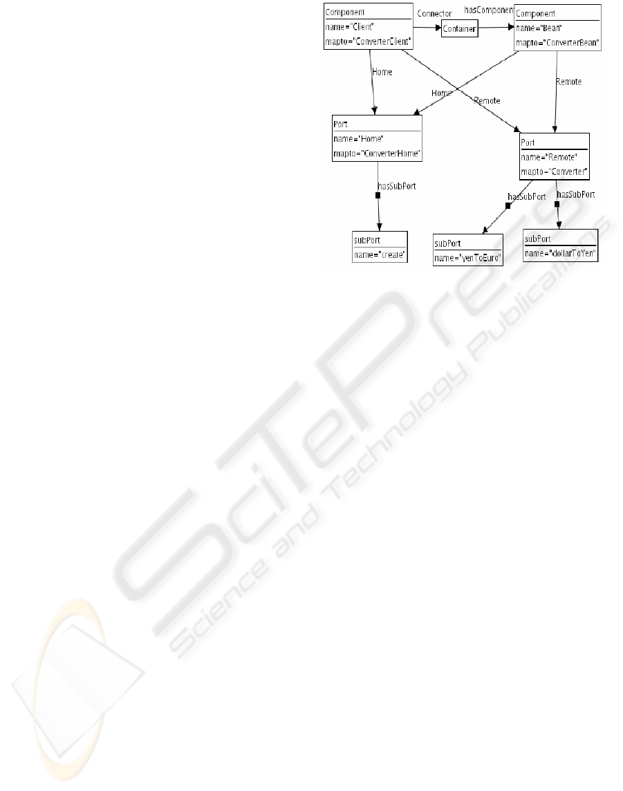
The figure 6 shows a graph produced by the
architecture mapping rules. In this figure a node may
be of type Component, Port, Subport or Container.
These nodes contain attributes and we have
especially shown two attributes that are name that
represents the name of the original Java Concept and
mapto representing the name of such a concept in
the ACME description. In this example the two
produced components are the result of mapping a
Java Client class and an EJB. The Ports represent
the Home and Remote interfaces of the EJB. The
Subports represent the methods and the container is
represented by a connector.
6 IMPLEMENTING THE
CHANGE IMPACT ANALYSIS
WITH A GRAPH REWRITING
SYSTEM
The change impact propagation has been
implemented by rules like the one shown by the
figure 2. These rules create nodes of type Impact as
a consequence of applying a change operation. The
node of type Impact contains some attributes that
describe the cause of the impact, etc. These nodes
are related to the affected artefacts. We established
taxonomy of changes by considering the basic
operations applied to nodes and edges that are insert,
delete and modify. So, for each nodes and edges
types we considered the three basic operations and
then we implement three techniques or processes to
deal with change impact that are: total propagation,
partial propagation and change-and-fix propagation.
The total propagation technique consists of
propagating the change of a node or an edge to all its
neighbours and to apply recursively this technique to
these neighbours. This technique is useful to obtain a
general idea about the potential effect of a change.
The partial propagation techniques are similar to
the total propagation technique except the fact that
we consider only specified nodes and edges types.
This technique is useful if we want, for instance, to
consider only the change propagation of a class to
other classes through inheritance relationship.
The change-and-fix propagation technique
consists of propagating the impact step by step. This
Figure 5: The abstract graph of a Java application.
ICEIS 2006 - INFORMATION SYSTEMS ANALYSIS AND SPECIFICATION
258
technique may be used as a guide to implement the
change.
We defined three sets of impact propagation
rules:
• The source code horizontal impact
propagation rules that consider only the
artefacts of the source code.
• The architecture horizontal impact
propagation rules that deal with the ACME
artefacts.
• The vertical impact propagation rules that
propagate the source code changes to the
related ACME artefacts and vice versa.
7 CONCLUDING REMARKS
In this paper, we presented the use of both Graph
eXchange Language and graph rewriting systems to
achieve more interoperability and flexibility of
implementing the software evolution activity. The
GXL provides an easier integration of several tools
that may be developed using different languages or
technologies. The graph rewriting systems provide
some facilities to define and implement rules
intended to provide reasoning capabilities. These
facilities such that the visual definition of the rules
and the inconsistency analysis make it more flexible
the implementation of software evolution tasks.
The use the graph rewriting rules eliminates the
impedance mismatch. In fact, artefacts and processes
dealing with them are all represented by graph
theory concepts.
The graph rewriting rules may be used in both
reverse and forward engineering. These may be
used, for instance, to implement model
transformation processes as defined in the Model
Driven Architecture (Soley, 2000) approach. So, one
may write graph rewriting rules that transform a
PIM (Platform Independent Model) to PSM
(Platform Specific Model) process. We are now
extending the artefacts model by non-functional
features of the software like quality measurements.
This will aid us to refine the change impact
propagation and architecture recovery
understanding. It will be then possible to analyse the
effect of changing the software structure on various
software quality criteria. We are also defining new
rules that detect design patterns and match
architectural styles from source codes. These are
formalized by type graphs and the rules try to match
these types graphs with elements of source code
graphs.
Figure 6: An example of architecture graphs.
REFERENCES
Aldrich, J., 2002. Aldrich, J., Chamber, G. and Notkin, D.
ArchJava: Connecting software architecture to
implementation. In International Conference on
Software Engineering (ICSE), May 2002.
Bouneffa, M., 1999, Bouneffa, M., Basson , H. and
Deruelle, L. Analyzing the impact of schema change
on application programs. In the proc. of the 1st
International Conference on Enterprise Information
Systems (ICEIS'99).
CLIPS, 2005, A tool for Building Expert Systems.
http://www.ghg.net/clips/CLIPS.html
Deruelle, L., 2001a, Deruelle, L., Bouneffa, M., Melab ,
N. and Basson, H. A Change Propagation Model and
Platform For Multi-Database Applications. In Proc. of
the IEEE International Conference on Software
Maintenance (IEEE-ICSM'2001), Florence, Italy, Nov.
6-10, 2001.
Deruelle, L., 2001b, Deruelle, L., Bouneffa, M., Melab ,
N. and Basson, H. Analysis and Manipulation of
Distributed Multi-Language Software Code. In
Proc. of the IEEE International WorkShop on Source
Code Analysis and Manipulation (IEEE-SCAM'2001),
Florence, Italy, Nov. 10, 2001.
Ermel, C., 1999, Ermel, C, Rudolf, M. and Taentzer, G.
The AGG approach: Language and environment. In
Handbook of Graph Grammars and Computing by
Graph Transformation. Volume 2. World Scientic,
1999.
Friedman-Hill, E.J. 1998, Jess, The Java Expert
System Shell. Distributed Computing Systems. Sandia
National Laboratories. (Friedman-Hill, E.J. 1998)
http://herzberg.ca.sandia.gov/jess
Garlan, D., 2000, Garlan, D., Monroe, R.T. and Wile, D.
Acme: Architectural description of component-based
ON IMPLEMENTING INTEROPERABLE AND FLEXIBLE SOFTWARE EVOLUTION ACTIVITIES
259

systems. In Foundations of Component-Based
Systems, pages 47--68. Cambridge University Press,
2000.
Griswold, W.G., 1990. Griswold, W.G. and Notkin, D.
Program restructuring to aid software maintenance.
Technical Report 90-08-05, Dept. of Computer
Sciences and Engineering, University of Washington,
Seattle, WA 98195 USA, September 1990.
Gwizdala, S., 2003. Gwizdala, S., Jiang, Y., Rajlich, V.
Jtracker - a tool for change propagation in java. In
Proc. of CSMR’2003, pages 223--229, 2003.
Holder, O., 1999, Holder, O, Ben-Shaul, I. and Gazit, H.
Dynamic layout of distributed applications in Fargo.
In International Conference on Software Engineering,
1999.
Holt, R., 2000, Holt, Winter, R.A., Schürr, A. and Sim, S.
GXL: Towards a standard exchange format. In 7th
Working Conference on Reverse Engineering, pages
23 -- 25, Brisbane, Queensland, Australia, November
2000.
Korman, W. 1998, Korman, W and Griswold, W. G.
Elbereth: Tool support for refactoring java programs.
Technical Report CS98-576, Department of Computer
Science and Engineering, University of California,
San Diego, April 1998.
Melab, N., 1999, Melab, N., Basson, H., Bouneffa, M.
and Deruelle, L. Performance of Object-oriented
Code: Profiling and Instrumentation. In the Proc. of
the IEEE International Conference on Software
Maintenance (IEEE-ICSM'99), Oxford, UK., Aug. 30
- Sep. 3, 1999.
Mitchell, B.S., 2002. A Heuristic Search Approach to
Solving the Software Clustering Problem. PhD thesis,
Drexel University, Philadelphia, PA, Jan. 2002.
Murphy, G., 1997, Murphy, G. and Notkin, D.
Reengineering with reflexion models: A case study.
IEEE Computer, 17(2):29--36, 1997.
Rajlich, V., 1997. Rajlich, V. Propagation of change in
object-oriented programs. In ESEC/FSE'97 Workshop
on Object-Oriented Reengineering, Zurich, September
1997.
Rashid, A., 2005, Rashid A., Sawyer, P. A database
evolution taxonomy for object-oriented databases:
Research Articles. Journal of Software Maintenance
and Evolution: Research and Practice, Volume 17
Issue 2, March 2005
ObjectStore, 1998. Object Design Inc. ObjectStore PSE
Resource Center. http://www.odi.com. 1998.
OMG, 2002, Meta-Object Facility (MOF), version 1.4,
http://www.omg.org/technology/documents/formal/mo
f.htm
OMG, 2005, MOF 2.0 / XMI Mapping Specification, v2.1,
http://www.omg.org/technology/documents/formal/xm
i.htm
Soley, R., 2000, Soley, R and the OMG Staff Strategy
Group. Model Driven Architecture. White Paper of the
Object Management Group. Sept. 2000.
(ftp://ftp.omg.org/pub/docs/omg/00-11-05.pdf)
Sousa, J.P., 1999. Sousa, J.P. and Garlan, D. Formal
modeling of the enterprise javabeans component
integration framework. In World Congress on Formal
Methods, pages 1281--1300, 1999.
Sun Microsystems, 2002. J2ee platform specification.
http://java.sun.com/j2ee/, 2002.
Vinoski, S., 1997. Corba: Integrating diverse applications
within distributed heterogeneous environments. IEEE
Communications Magazine, 14(2), February 1997.
W3C, 2001. XsSL transformations (XSLT).
http://www.w3.org/TR/xslt.
W3C. Extensible markup language (xml) 1.0 (second
edition), w3c recommandation. Technical Report
http://www.w3c.org/TR/2000/REC xml-20001006,
World Wide Web Consortium, 2000.
ICEIS 2006 - INFORMATION SYSTEMS ANALYSIS AND SPECIFICATION
260
