
ROUTING IN THE “UMBRELLA” ARCHITECTURE
A. D. Sotiriou, P. Kalliaras, N. Mitrou
School of Electrical and Computer Engineering, Computer Network Laboratory
National Technical University of Athens
9 Heroon Polytechneiou Street, Zographou 15773, Athens, Greece
Keywords: Distributed hash-table, P2P architecture, overlay networks, routing algorithm.
Abstract: Routing in a Peer-to-Peer environment faces a number of challenges, mainly due to its distributed nature. In
this paper we evaluate a new distributed hash table architecture that is able to provide efficient routing
through a fixed-size table. By introducing a set of base algorithms, multiple replication schemas, virtual
nodes and a variable repair mechanism, we are able to ensure successful lookups of published keywords.
Along with theoretical analysis of our proposed work, we present extensive simulation results that testify
and evaluate our protocol.
1 INTRODUCTION
One of the core issues in every network topology is
the routing algorithm applied. This has been
extensively studied and established in constantly
connected networks. However, such algorithms as
OSFP (Moy,1998) require a relevantly good
knowledge of the network topology and assume
constant or almost constant links, at least for a
desired period of time. The introduction however of
ad-hoc and Peer-to-Peer (P2P) networks necessitates
the implementation of new routing strategies that are
able to operate in robust and distributed
environments.
Various solutions have been proposed and there
has been an increasing interest in the adaptation of
distributed hash tables into such networks. Most of
these algorithms are characterized by the size of the
routing table, as this modulates both the algorithms’
efficiency and tolerance to errors. This paper
introduces the Umbrella architecture, a novel routing
scheme based on a distributed hash table of fixed-
size on top of an overlay network. We provide
efficient algorithms for keyword publication and
lookup along with a number of extensions that
improve the system’s tolerability. The key novelty
of our work lies in the fixed-size routing table, as
opposed to other algorithms which are usually
proportional to the network’s size.
The rest of the paper is organized as follows. In
chapter 2 we present related work and ideas that
have been thoroughly studied prior to our
architecture design and in chapter 3 we present our
novel architecture. In the following chapter we
provide in detail the routing algorithms invoked by
our protocol and introduce a number of extensions
that enrich our protocol. Chapter 5 discusses a
number of results obtained through our simulation of
the system and finally, chapter 6 offers useful
conclusions.
2 RELATED WORK
The firsts to introduce routing algorithms that could
be applied to DHT systems were Plaxton, Rajaraman
and Richa (Plaxton,1997). The algorithm wasn’t
developed for P2P systems, and thus every node had
a neighborhood of Ο(logN) and inquires resulted in
Ο(logN) steps. It was based on the ground rule of
comparing one byte at a time until all bytes of the
identifier (or best compromise) were met. A key
feature of their scheme was that the routing table
could be transformed as thus the overlay distance
between nodes could be of a constant factor of the
real distance, when all latencies between nodes are
known. Our scheme meets the logarithmic growth of
inquiries introduced by Plaxton, and even though
nodes are not placed within constant distance from
each other, this is not an issue as it was only
implemented in a theoretical study and not for P2P
environments. A variation of the Plaxton algorithm
was developed by Tapestry (Zhao,2004), properly
adjusted for P2P systems (where overall state is not
available). The algorithm once again tackles one
digit at a time and through a routing table of
234
D. Sotiriou A., Kalliaras P. and Mitrou N. (2006).
ROUTING IN THE “UMBRELLA” ARCHITECTURE.
In Proceedings of the International Conference on Wireless Information Networks and Systems, pages 234-241
Copyright
c
SciTePress
β*log
β
N neighbors routes to the appropriate node,
resulting in a search of log
β
N maximum steps. Our
architecture is based on the fundamentals ideas set
by Plaxton and further developed by Tapestry, but is
also fine-tuned for P2P systems that are likely to
have an enormous amount of population and
content.
Pastry (Rowstron,2001) is similar to Tapestry but
added a leaf set of neighbors that the node first
checks before referring to the routing table. Also a
different neighbor set is maintained for tolerability
issues. Each node maintains a neighborhood of
log
2
bN rows with (2
b
-1) elements in each row and
requires a maximum of O(log
2
bN) steps for enquires.
Proper routing is maintained as long as (L/2) nodes
are available in the neighborhood of each node.
Once again, the variable size of each node’s table
limits the algorithm’s scalability. In addition, our
algorithm’s results showed that inquiries can be
successful even with less available nodes in the
routing table. In Chord (Stoica,2001) a different
approach was applied, placing nodes in a circular
space and maintaining information only for a
number of successor and predecessor nodes through
a finger table. Routing is established through
forwarding queries to the correct successor. Even
though the basic Chord mechanism only requires the
knowledge of one successor, modifications where
needed in order for the system to be applicable to a
robust environment, introducing a finger table of
O(logN) size.
CAN (Ratsanamy,2001) furthered on Pastry’s
alternation and implied DHT in a d-dimensional
Cartesian space based on a d-tore. The space is
constantly divided and distributed amongst nodes,
which must maintain information about their
neighbors and route by following the Cartesian
space. CAN provides a constant O(d) table but,
unlike our algorithm, requires O(dN
1/d
) steps for
lookups. Finally, Kademlia (Maymounkov,2002)
bases nodes in a binary-tree through identifiers.
Each node of the tree retains information concerning
one node from each leaf, other than the one it
resides. It also differentiates by applying an XOR
comparison on identifiers instead of the casual
comparison of each bit, adopted by all other
algorithms. Our algorithm familiarizes with
Kademlia by inserting nodes in a B-tree form, which
is much more versatile and fault-tolerant.
3 ARCHITECTURE OVERVIEW
The proposed architecture is based on the creation of
an overlay network, where all inserting nodes are
identified by a unique code, asserted by applying the
SHA-1 (NIST,1995) hash-function on the
combination of IP and computer name, which
returns an 160-bit identifier. This hash-function has
been proven to distribute keys uniformly in the 160-
bit space and thus provide the desired load balancing
for both the user space and the content space, as the
same function is applied to each content destined for
distribution in the system.
The main objective of the Umbrella architecture
is to insert and retain nodes in a simple and well
structured manner, thus querying and fetching of
content is both efficient and fault-tolerant. In
addition, each node will need only to retain up-to-
date information of a limited, constant number of
neighboring nodes, such allowing the system to
escalate in population of both users and content.
Each node is inserted in the system through an
existing node, which announces the new entrance.
When this procedure has ended successfully, the
new node can, having acquired and informed all
neighboring nodes, continue to publish all of its
content. The publishing procedure is similar to the
insertion mechanism, as content is characterized by
a number of keys, which after being hashed can be
forwarded in the same manner. All keys are
published in an existing node that its identifier is the
closest match to the key identifier. In a similar
fashion, querying is performed by routing the
request to the node with identifier closest to the
desired key.
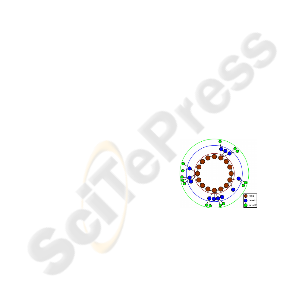
Figure 1: The Umbrella architecture.
The overlay network is constructed in the form
of a loose B-Tree, where each node is placed in a
hierarchy tree with a parent node and b child nodes.
All nodes are placed along the tree structure, without
being required to fulfil pre-defined ranges as in a
proper B-tree structure, and are responsible for
updating their connections with neighbouring nodes
that reside on either the parent, sibling or child level.
Thus, each node operates autonomously and no
central coordination is needed to maintain the
structure’s integrity. Along with obvious
connections (parent, child and sibling level of each
ROUTING IN THE “UMBRELLA” ARCHITECTURE
235

node), further links to a limited number of nodes in
the near vicinity are kept in record for fault-tolerant
operations. Figure 1 illustrates the structure of this
loose B-Tree. Each level n of the structure is capable
of withholding b
n+1
nodes. Each node has a unique
parent node, which is always one level higher, and a
maximum of b children at a lower level. The
Umbrella overlay network is configured with the
following simple rule. The relation between a parent
node at level n and a child node (which must by
default reside on level n+1) is defined as such and
only such that :
• The n+1 first digits of the parent’s identifier are
equal with the corresponding numbers of the
child’s identifier
• The n+2 digit of the child’s identifier determines
the child’s position in the parent’s child list
The use of a consistent hash function to
distribute identifiers in our node and content space
allows the construction of a well balanced loose B-
tree. The structure becomes even more balanced as
node population increases and nodes fill empty
spaces. The consistent hash function also balances
key distribution among nodes as stated in
(Karger,1997).
As in most DHT systems, a routing table is
maintained by each node in order to route incoming
messages. Each node is responsible for keeping the
table up-to-date by issuing messages to all nodes in
its table at different intervals. The routing table in
our architecture consists of three different sets, a
basic, an upper and a lower set. The basic set stores
nodes and information needed for basic routing
operations under fault-free conditions. The upper
and lower set store additional indexes to nodes in the
upper and lower levels, correspondingly, which are
utilized when nodes in the basic set become
unreachable. These three sets constitute the node’s
neighbourhood table and are presented in Table 1.
Table 1: Fields of the neighborhood table.
Field Set Description
Level Basic The level it resides
Right Basic The non-empty node to the right
Left Basic The non-empty node to the left
Up Basic The parent node
Right2 Upper
The node residing to
the right of the parent node
Left2 Upper
The node residing to the
left of the parent node
Up2 Upper The parent’s parent node
Right3 Lower
One (random) child
of the node to the right
Left3 Lower
One (random) child of
the node to the left
Umbrella Basic All children nodes
Umbrella2 Lower
A (random) child node
from each child
Our architecture’s structure and routing table
described so far ensure that a published key can be
located by an appropriate query within logarithmic
overlay steps to the total size of the network. This is
stated and proved within the following two
theorems:
Theorem 1. Given an Umbrella network of N
nodes with identifiers of base b acquired by a
consistent hash function, the maximum height of the
loose B-tree structure is of logarithmic scale.
Proof : Let b denote the base of our identifiers, N
the total number of nodes and k a particular level in
the Umbrella structure. Then according to the
Umbrella protocol, in each level a maximum of b
k
nodes can reside, with b
0
=1 as stated for the first
node that creates the network. Thus, if m denotes the
number of levels required for the above population
of nodes, we acquire, with high probability, the
following relation:
[]
∑
=
++
−+−=⇔
⇔
−
−
=
−
−
=
=
m
k
b
mm
k
bNm
b
b
b
bb
b
N
0
110
1}1)1({log
1
1
1
(1)
Thus the maximum height m of our structure is
of O(log
b
N).
Theorem 2. A successful lookup in an Umbrella
network requires with, high probability, O(log
b
N)
steps.
Proof : Suppose that a node p that resides at level
l
p
is seeking for a specific key k that resides within
our network in another node f at level l
f
. If m
denotes the number of levels of the current network,
N the nodes and b the base of identifiers, then we
could argue that the worst case scenario would
require both nodes to reside at level m and with
maximum distance between them (thus node p is a
m-depth child of the first child at level 0 and on-
forth and node f is the m-depth child of the b child at
level 0 and on-forth). In this case, the lookup must
first ascend all the way to the top of our structure
(thus m steps) and then descend to the bottom (m
steps again). In total, a maximum of 2m steps are
required. Hence, from theorem 1, the required
maximum steps for a successful lookup is, with high
probability, of O(log
b
N) steps.
4 ROUTING ALGORITHMS
During the creation of the overlay network, the b
first nodes to enter create the new network by
placing themselves on the top level and forming a
ring. As new nodes arrive, they are placed according
to their identifier. A node only needs to contact an
existing node in the system in order to be inserted
WINSYS 2006 - INTERNATIONAL CONFERENCE ON WIRELESS INFORMATION NETWORKS AND SYSTEMS
236
(mechanisms for fetching existing nodes are not in
the scope of this paper as numerous such techniques
exist (Francis,1999)). Only the first nodes are
automatically inserted regardless of their identifiers;
all subsequent nodes are placed within the system
according to the insertion algorithm. The insertion
mechanism is quite simple and consists of the
following steps:
• Issuing a request on a connected node
• The node checks if the n+1 first digits of its
identifier match, where n is the level it resides
• If not it forwards the message to its parent
• If yes it forwards it to the child with the n+2
digit common with that of the new node
• If such a child does not exist then the new node
is placed as a child to the current node
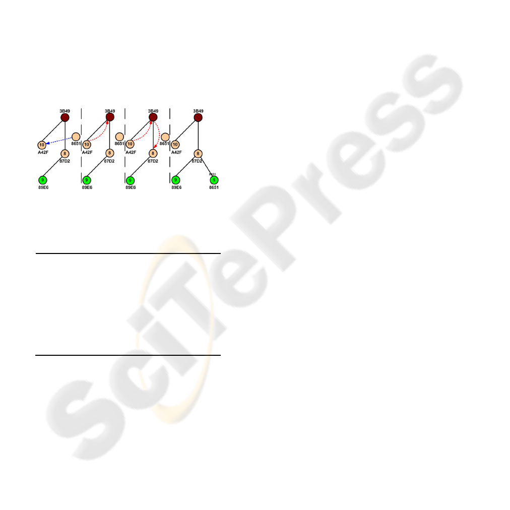
The publish procedure is similar to insertion and
is therefore suppressed. Conversely, the lookup
mechanism is executed as shown by example in
Figure 2.
Figure 2: Instance of lookup mechanism.
The final mechanism provided by our protocol is
that of voluntary departure from the system and is
given as pseudo-code in Figure 3.
1. delete ( )
2.
if ( has_kids( ) )
3.
rand_kid = choose_random_kid( )
4.
if ( rand_kid.has_kids( ) )
5.
rand_kid.delete( )
6.
else
7.
rand_kid.move_published( )
8.
rand_kid.copy_neighbors( )
9.
inform_neighbors( rand_kind )
10.
disconnect( )
11.
else
12.
this_node.father.move_published( )
13.
inform_neighbors( this_node.father )
14.
disconnect( )
Figure 3: Example for voluntary departure mechanism.
The algorithms presented so far embody the
main mechanisms of our routing protocol and are
capable of maintaining the system stable and fully
functional under normal conditions. The system is
however liable to node departures, either intentional
or due to network disconnections, which we will call
“node failures”. Through changes in the algorithms
already presented we allow the system to bypass
node failures. Most changes are based on using the
upper and lower set of our neighbourhood table to
bypass nodes that aren’t responding. The upper set is
utilized to forward messages to nodes of a higher
level while the lower set for nodes on a lower level.
In the first case, when a node is unable to contact its
parent node it attempts to forward requests
consequently to:
1. the parent’s parent node (Up2)
2. the node to the right of the parent node (Right2)
3. the node to the left of the parent node (Left2)
Whichever of the above succeeds first will
terminate the mechanism. Similarly, the lower set is
utilized for bypassing child node failures. In order to
address the problem of node failures even further,
we have designed a repair mechanism, which is
invoked whenever such a failure is detected. The
algorithm utilizes the voluntary departure algorithm
in order to repair a failure to a child node. It can be
proven that all other failures can be transformed into
a child failure through contacting nodes in the
neighbourhood table and forwarding the repair
message. Once the appropriate node is reached, a
variation of the departure algorithm is evoked in
order to repair the failure by substituting the failed
node with one of its children or by deleting it if none
is available and informing all of its neighbours.
Having presented the core structure and logic
behind our routing protocol, we will continue with a
number of extensions that improve the system’s
performance. The first extension introduces the use
of replication schemas, which has been shown to
increase the robustness of content distribution
systems (Ghodsi,2005). In this paper we have
implemented three additional replication schemas.
We must note that, in contrast with other schemas
found in different protocols, we only replicate
published keywords in nodes and not the actual
content.
Our core routing protocol publishes a keyword in
a single node, the one with closest identifier to that
of the keyword. All three replications schemas retain
this quality and enhance it by also publishing the
keyword to a number of additional nodes, from
which one can recall a successful lookup. Our three
variations are the following:
1. Local Spread Replication (LSR)
The keyword is also published in all nodes
residing in its neighboring table.
2. Inverse Replication (IR)
This mechanism publishes keywords to the
closest match and to the inverse closest match.
3. Local Spread Inverse Replication (LSIR)
It implements a local spread in both the closest
and the inverse closest match.
The second extension implemented allows
nodes to participate in a number of virtual networks,
with a different identifier in each one. This allows
ROUTING IN THE “UMBRELLA” ARCHITECTURE
237
each node to have a different set of neighbours and
thus increase its tolerability substantially. In order to
achieve this, we have defined a number of singular
identifier assignment functions that transform the
original identifiers into a new set of identifiers. This
new set is then used to allocate nodes and route
requests in the virtual networks. We have defined 7
different such functions, which are given below:
1. Inverse Identifier (II)
This function inverses the identifier
2. Inverse per Pair (IP)
The identifier’s digits are inversed by pair
3. Inverse per Pair and Whole (IPW)
All digits are inversed by pair and the result is
inversed as a whole
4. Inverse by Halves (IH)
The II function is applied to the first and second
half of the identifier independently
5. Switch Halves (SH)
The first and second halves are switched
6. Random Reordering (RR)
A random reordering of the identifier’s digits
7. Second Random Reordering (SRR)
Same as RR with different random generator
5 SIMULATION RESULTS
In order to testify our architecture’s integrity and
elaborate on its efficiency we have modeled our
system and its algorithms using the neurogrid
(Joseph,2003) simulator. All of our simulations were
executed on a 3.2MHz PC with 512Mb of RAM and
based on Java.
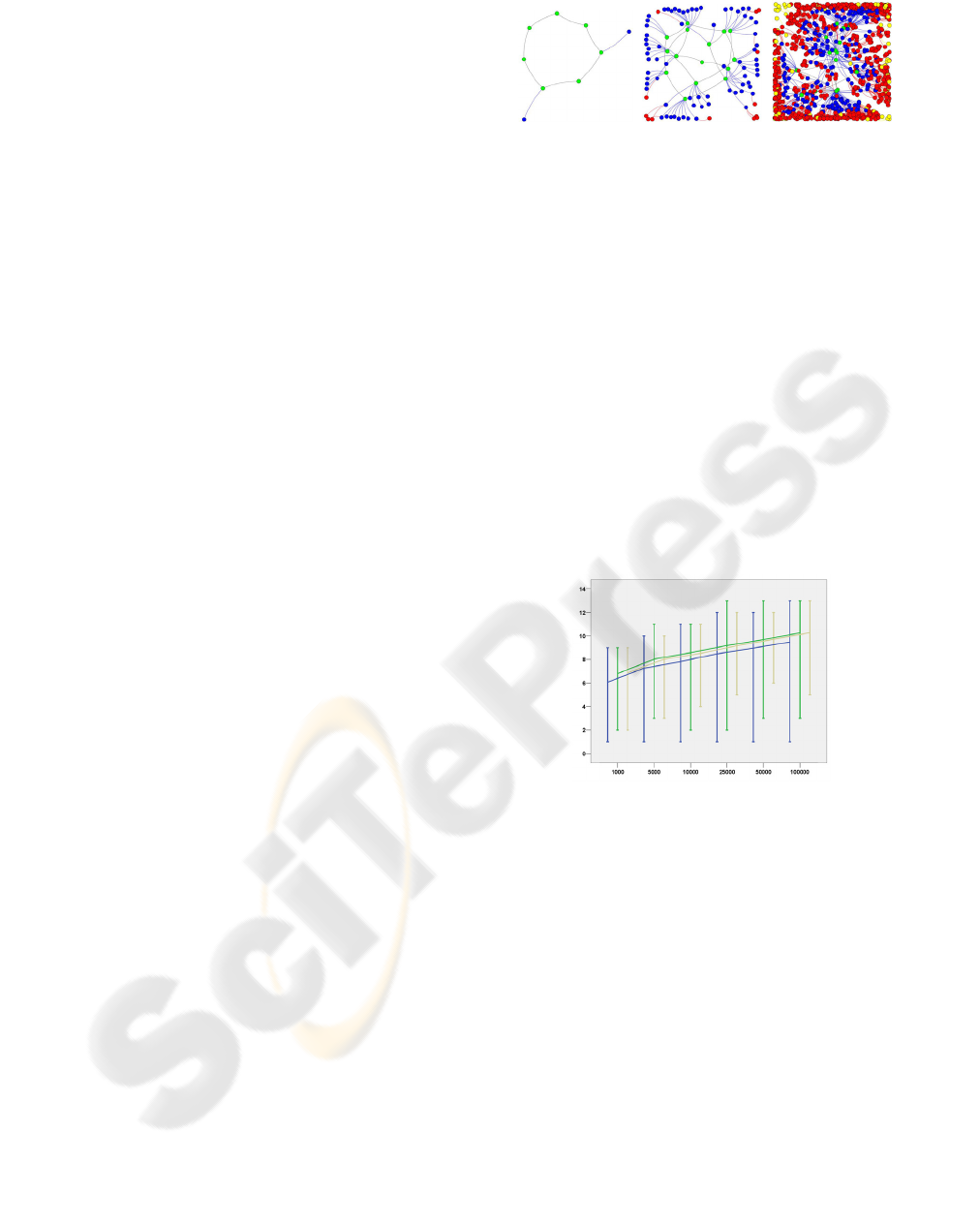
Prior to our simulation analysis on the efficiency
of our protocol and its performance in general, we
will present the Umbrella topology, as this derives
from the architectural design. For this purpose, we
have used the JUNG (Madadhain,2005) library,
which allows the visual representation of networks.
Once our overlay network has been created and fully
populated, we produce an instance of the network
topology by representing each node (peer) along
with the parent-children pairs of connections. In
addition, we color each node according to the level it
resides, providing an in-sight view of our protocol.
In Figure 4, a number of such instances are given for
different node populations varying from 10 and up
to 1,000 nodes. As can be seen, nodes are spread
along the B-tree structure and although we do not
imply restrictions on the minimum or maximum
number of children for each level (as in a proper B-
tree) the structure is still quite compact.
Figure 4: The Umbrella topology for 10, 100 and 1,000
nodes.
The first part of our initial simulations tested the
basic functionality of the routing protocol under
normal conditions, in other words without the
presence of node failures. All of the results
presented in this set provided 100% success. We
thus present only the number of hops required for a
successful insertion, publish and lookup with a
varying population of nodes. As is seen in Figure 5,
the number of hops grows logarithmically with node
population in all mechanisms. We also notice that
the variance is mainly towards lower number of
hops while higher values are only a fraction larger
than the mean. If we further analyze the results from
the previous figures we will observe that the average
hops required by each operation are given by
2.5*log
16
N. Thus it satisfies theorem 3 and only
introduces a constant factor of 2.5.
Figure 5: Number of hops for insert publish and lookup
operations.
In the next set of simulations we tested our repair
mechanism in the case of failing nodes in order to
evaluate its effect on the success rate. We conducted
simulations with variant node populations from
1,000 up to 100,000 nodes and periodically issued
random node failures in steps of 10% from 0 up to
80%. An important metric in our repair mechanism
is the rate at which the mechanism is invoked. More
precisely, each node invokes the mechanism in two
cases; either whenever a failure is detected during a
call of one of the protocol’s algorithms or during the
course of a routing table consistency check, which is
issued periodically by each node. The former is
constant and issued throughout our simulations,
while the latter varies as we have conducted
simulations with different consistency check
periods. In the results presented here we have varied
WINSYS 2006 - INTERNATIONAL CONFERENCE ON WIRELESS INFORMATION NETWORKS AND SYSTEMS
238
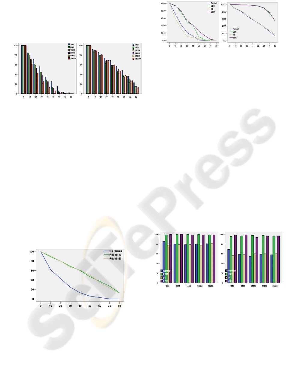
this period and executed simulations for period times
10T and 20T, where T is a constant representing
communication activity of each node (in our case T
equals to 100 messages), ensuring that an inactive
node will not suffocate the network with repair
messages.
Figure 6: Successful lookups as a function of failures
without and with repair 10T.
Firstly we investigate the impact of the repair
mechanism on the success rate of lookup operations.
As seen in Figure 6 the repair mechanism
dramatically increases the success rate regardless of
the node population and the check period. The
protocol is able to produce linear deduction of the
successful lookup rate as opposed to the logarithmic
decrease observed without the repair mechanism.
The impact of the repair mechanism is better
observed in Figure 7, where we have mapped the
success rate of lookups against node failures for the
case of 100,000 nodes, for no repair, repair period
10T and 20T. The results were dramatically
improved in both cases where the repair mechanism
was applied. The results obtained with repair period
10T are a fraction higher than those of 20T, which
was expected as nodes check their routing table’s
consistency less frequently.
Figure 7: Successful lookup for no-repair, 10T and 20T
repair.
In the second set of simulations we applied our
two protocol extensions, the replication schemas and
the virtual networks. We will present the effect of
each extension and evaluate the overall protocol
efficiency when all variations are applied.
Figure 8: Lookup success ratio for different replication
schemas and repair periods.
Firstly we will evaluate the effect of the different
replication schemas to the efficiency and tolerability
of our routing protocol. In our simulations, we
varied the node population from 1,000 up to 50,000
nodes and generated failures in steps of 10% from 0
up to 80%. In the first diagram of Figure 8 we have
sketched the successful lookup ratio as the node
failure ratio increases, for a network of 50,000 nodes
and varying replication schemas and repair periods.
We observe that while the inverse replication (IR)
schema does not better the protocol’s efficiency,
both the local spread replication (LSR) and the local
spread inverse replication (LSIR) schemas improve
the protocol’s success rate vastly. These
improvements are even more significant when the
repair mechanism is applied, as seen in the second
diagram of Figure 8. The protocol is able to sustain
100% success rates up to 30% fail rates when a
repair period of 10T and either LSR or LSIR
schemas are applied. Moreover, success rates higher
than 80% are achieved for up to 70% fail rates when
a 10T repair period is applied and a LSR or LSIR
replication schema is implemented.
Figure 9: Lookup success ratios for different replication
schemas and failure ratios.
In the next figure, Figure 9, we can see the
impact of node population on the combination of
replication schemas. We have controlled the repair
period and retained it constant and equal to 10T and
varied the failure ratio between 20% and 60% for the
four different replication schemas and for node
populations of 1,000 up to 50,000. As can be seen,
the node population does not affect the success rate
for any replication schema or failure ratio. This
ROUTING IN THE “UMBRELLA” ARCHITECTURE
239
shows that our protocol can escalate and support
intense node populations.
Figure 10: Per node messages for different replication
schemas as a function of node population.
Finally we investigated the drawback of the
proposed replication schemas. As can be seen from
Figure 10 the new schemas incur an increase in the
number of messages exchanged between peers. The
use of the IR schema doubles the number of
messages required while the LSR and LSIR induce
an increase by a factor of 2.5 and 6.0 respectively.
Even though these changes may sound significant
they are actually quite efficient since even in the
case of 50,000 nodes and LSIR replication schema
the total does not exceed that of 45 messages for the
whole duration of the simulation.
Figure 11: Average of successful lookups for varying
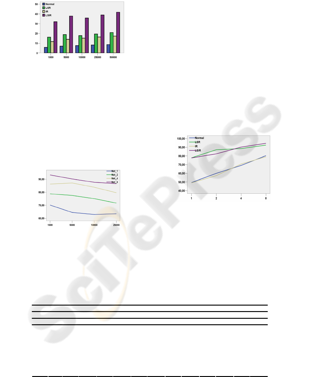
virtual networks as a function of node population.
In our final series of simulations we will try to
evaluate the effect of the virtual networks extension.
During this analysis, in many cases, we present
aggregated results due to the multiple variables that
affect each simulation. All presented results evaluate
the case of having 1 (no virtual networks), 2 , 4 or 8
virtual networks. In Figure 11 the average of
successful lookups is shown for varying virtual
networks as a function of node population. The
average derives from the aggregation of all
combinations of replication schemas, repair periods
and failing ratios. With that in mind, we must point
out that the optimum success rate for our protocol is
much higher than the average shown in this figure.
However, the average presents an indication of the
virtual networks’ effect on the success rate. It is
clear form the data on the figure that as the number
of virtual networks increases the success rate
improves tremendously, and from an average of
around 65% for no virtual networks it raises to 75%,
85% and 90% for the cases of 2, 4 and 8
respectively. This is further testified by observing in
Figure 12 how virtual networks affect the success
rate for different replication schemas. Once again,
the success rate increases linearly with the number
of virtual networks, for all replication schemas.
Figure 12: Average of successful lookups for varying
replication schemas as a function of virtual networks.
Having established the beneficial effect of the virtual
networks extension, we will now present the
optimum protocol performance. In Figure 13 we
seek the optimum performance of our protocol. We
vary the number of virtual networks between 1 and 8
and the repair period between 0 and 10T, for the
average of all replication schemas. As can be seen,
Table 2: Success rates for combinations of virtual networks, repair periods and replication schemas per node failure ratio.
Network 2 4 8
Repair 10T 20T 10T 20T 10T 20T
Replication LSR LSIR LSR LSIR LSR LSIR LSR LSIR LSR LSIR LSR LSIR
0
100 100 100 100 100 100 100 100 100 100 100 100
10
100 100 100 100 100 100 100 100 100 100 100 100
20
100 100 100 100 100 100 100 100 100 100 100 100
30
100 100 99 99 100 100 100 100 100 100 100 100
40
100 100 99 100 100 100 100 100 100 100 100 100
50
99 100 99 99 100 100 100 100 100 100 100 100
60
99 99 98 99 100 100 100 100 100 100 100 100
70
96 97 93 97 99 100 96 99 100 100 96 100
Failure %
80
73 86 67 77 98 98 82 97 98 99 97 99
WINSYS 2006 - INTERNATIONAL CONFERENCE ON WIRELESS INFORMATION NETWORKS AND SYSTEMS
240

for the case of 8 virtual networks, a 100%
mechanism, while this rate increases up to 80%
when a 10T repair period is applied. In the latter
case, even with 4 virtual networks an optimum
performance is achieved for up to 60-70% node
failures.
Figure 13: Success rate for different combinations of
virtual networks and repair period as a function of failures.
Finally we will present some conclusive results
for the optimum performance of our protocol. In
Table 2
we can see the success rates for the best
combinations of virtual networks, replication
schemas and repair periods as node failures increase.
For all combinations, the protocol routes
seamlessly when node failures don’t exceed a 40-
50% ratio. If we want our protocol to tolerate even
more node failures then either 4 or 8 virtual
networks should be implemented, regardless of the
check period or the replication schema. Here we
point out that the repair mechanism is a pre-
requirement, in contrast to the repair period, which
can be relaxed to 20T without significant loss in
performance. The same applies for the replication
schema; the LSR schema must be at least applied but
the LSIR is not vital as results are only slightly
better.
6 CONCLUSIONS
Through the course of this paper we presented the
Umbrella protocol; a novel protocol based on a
distributed hash table that supports key publishing
and retrieval on top of an overlay network for
content distribution. We have analysed our protocol
and its algorithms through both theoretical and
simulation means and proved its corrective ness and
efficacy. Its main novelty lies in its fixed-size
routing table sustained by each node, which is able
to provide efficient routing even under contrary
conditions. The protocol has also proved to be
scalable due to its low traffic load demands. The
results obtained by our simulations proved that the
protocol, along with a number of valuable
extensions, is able to route seamlessly successful
lookups in O(log
b
N) steps even when more than
80% of the system’s population suddenly fails.
REFERENCES
Francis, P. (1999). “Yoid : Extending the Multicast
Internet Architecture,” White paper,
http://www.aciri.org/yoid
Ghodsi, A., Alima, L.,O., Haridi, S. (2005). “Symmetric
Replication for Structured Peer-to-Peer Systems”, The
3rd International Workshop on Databases, Information
Systems and Peer-to-Peer Computing, Trondheim,
Norway , August
Joseph, S. (2003). “An Extendible Open Source P2P
Simulator,” P2PJournal
Karger, D., Lehman, E., Leighton, F., Levine, M., Lewin,
D., Panigrahy, R. (1997). “Consistent hashing and
random trees: Distributed caching protocols for
relieving hot spots on the World Wide Web”, in
Proceedings of the 29
th
Annual ACM Symposium on
Theory of Computing, El Paso, TX
Madadhain J., Fisher D., Smyth P., White S., Boey Y.
(2005). “Analysis and Visualization of Network Data
using JUNG”, http://jung.sourceforge.net
Maymounkov, P., Mazieres, D. (2002). “Kademlia: A
peerto -peer informatic system based on the XOR
metric,” in Proceedings of IPTPS'02, (Cambridge,
MA)
Moy J. (1998). “OSPF Version 2”, Network Working
Group, RFC 2328
National Institute of Standards and Technology. (1995).
“FIPS Pub 180-1: Secure Hash Standard (SHA-1),”
Federal Information Processing Standards Publication
Plaxton, G., Rajaraman, R., Richa, A.W. (1997).
“Accessing Nearby Copies of Replicated Objects in a
Distributed Environment,” in 9th Annual ACM
Symposium on Parallel Algorithms and Architectures
(SPAA)
Ratsanamy, S., Francis, P., Handley, M., Karp, R. (2001).
“A scalable content-addressable network,” in ACM
SIGCOMM Conference, ACM Press, San Diego (CA)
Rowstron, A., Druschel, P. (2001). “Pastry: Scalable,
decentralized object location, and routing for large-
scale Peer-to-Peer systems,” in Middleware 2001
Stoica, I., Morris, R., Karger, D., Kaashoek, F.,
Balakrishnan, H. (2001). “Chord: A Peer-to-Peer
Lookup Service for Internet Applications,” in Proc.
SIGCOMM
Zhao, B. Y., Huang, L., Stribling, J., Rhea, S.C.,
Joseph,A.D., Kubiatowicz, J.D. (2004). “Tapestry: A
resilient global-scale overlay for service deployment,”
IEEE Journal on Selected Areas in Communications
ROUTING IN THE “UMBRELLA” ARCHITECTURE
241
