
SMART ANTENNAS IN UMTS LCR-TDD
Implementation of RSS Beamforming
Arjang Hessamian-Alinejad, Achim Seebens, Tobias Scholand, Admir Burnic,
Guido H. Bruck and Peter Jung
Lehrstuhl für KommunikationsTechnik, Universität Duisburg-Essen, 47048 Duisburg, Germany
Keywords: Beamforming, DSP (Digital Signal Processor), LCR-TDD (Low Chip-Rate Time Division Duplex), Regular
Spatial Sampling (RSS) Smart Antennas, UMTS (Universal Mobile Telecommunications System).
Abstract: In this communication a novel beamforming scheme is presented, which is based on regular spatial
sampling (RSS) of signals. RSS beamforming allows low-complexity algorithms for smart antennas, while
at the same time improving the performance of those systems. An implementation concept is presented,
which shows the feasibility of implementing RSS beamforming on today’s readily available hardware
platforms.
1 INTRODUCTION
In the LCR-TDD (Low Chip-Rate Time Division
Duplex) mode of UMTS (Universal Mobile
Telecommunications System), the application of
smart antennas is anticipated (Holma et al., 2002). A
smart antenna is the combination of an array antenna
with an appropriate signal processing algorithm,
which is applied to the signals coming from or going
to the antenna elements of the array antenna (Lehne
et al., 1999), (Correia,2001). Smart antenna
concepts range from simple switching between
directive antenna elements of an array antenna to
highly-sophisticated adaptive beamforming
techniques, which aim to maximize the signal-to-
interference-and-noise ratio (SINR) for the user of
interest during reception, while in the transmit
direction reducing the interference to other users as
far as possible (Lehne et al., 1999). Beamforming
can be viewed as spatial filtering by adjusting the
beam pattern of the array antenna through the
application of beamforming weights to the signals of
the antenna elements.
Here, we will focus on receiver beamforming. The
majority of beamforming concepts apply array
antennas with
a
K
identical wired antenna elements,
making the analysis and design of the array antenna
very simple. In order to avoid large unwanted side
lobes the antenna spacing must not be larger than
2
λ
, where
λ
is the wavelength of the radio signals
in mind. However, placing the antenna elements too
close increases the coupling between the antenna
elements and broadens the minimum achievable
beam width. Hence, in most arrays the antenna
element spacing is
2
λ
.
First the general concepts of conventional and the
novel Regular Spatial Sampling (RSS) beamforming
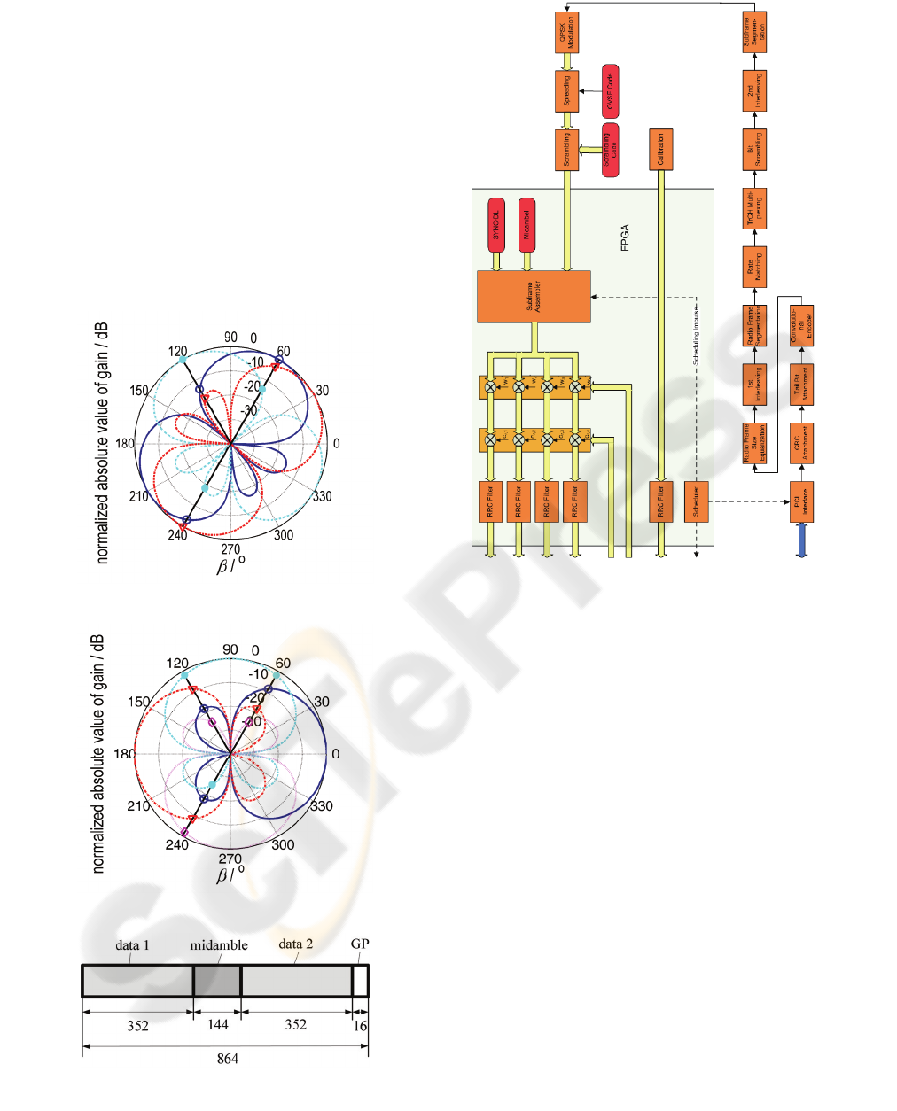
shall be considered. In figure 1, a scenario
consisting of three user signals impinging from the
Directions Of Arrival (DOA)
60
β
=°, 120
β
=°, and
240
β
=
°
, onto an array antenna is shown. The array
antenna is a UCA consisting of
a
4K = antenna
elements with an antenna element spacing of
2
λ
.
The conventional beamformer expresses a single
beam for each impinging wave, which are shown in
figure 1 in blue, magenta and red for the signals
impinging from
60
β
=
° , 120
β
=°, and 240
β
=
° ,
respectively. Looking at the blue beam steered in the
direction
60
β
=
° this beam not only receives the
user of interest, but also due to its side lobes the
other two impinging signals. These are considered
as interference in the conventional beamformer.
Likewise it is for the other two impinging signals.
The conventional beamformer can be viewed as a
spatial matched filter as it maximizes the signal-to-
noise ratio (SNR) in the receiver. However, since
the beamformer steers the beam into the directions
of the impinging signals, these directions have to be
estimated. Appropriate DOA algorithms like e.g.
177
Hessamian-Alinejad A., Seebens A., Scholand T., Burnic A., H. Bruck G. and Jung P. (2006).
SMART ANTENNAS IN UMTS LCR-TDD - Implementation of RSS Beamforming.
In Proceedings of the International Conference on Wireless Information Networks and Systems, pages 177-184
Copyright
c
SciTePress
ESPRIT (Paulraj et al., 1986) can become
computationally very complex.
The expression of beams into the DOAs of the
impinging signals can be seen as sampling the space.
As can be seen from the above discussion this is an
irregular spatial sampling, since the beams are
directed into the DOAs of the impinging waves,
which may be any directions. From the processing
of time domain signals it is known that processing of
irregularly sampled signals is often more complex
than the processing of regularly sampled signals.
This is the main idea of the novel RSS beamforming
technique, which represents a regular sampling of
the space (Seebens et al., 2004), (Scholand et al.,
2004).
Figure 1: Conventional beamforming.
Figure 2: Regular spatial sampling (RSS) beamforming.
Figure 3: Burst structure for the LCR-TDD mode of the
UMTS system (3GPP TS 25.221 V5.2.0, 2002).
Figure 4: Block diagram for the Node B transmitter.
Figure 2 shows the concept of RSS beamforming for
the same scenario as above for the conventional
beamforming. Contrary to conventional
beamforming the number of expressed beams does
not depend on the number of users. Instead a fixed
number of beams is expressed, which is suitable to
sample the space. For the circular array with
a
4K
=
antenna elements like the one for the conventional
beamformer there are four independent beams
possible, shown in figure 2 in blue, magenta, red and
violet for the directions
0° , 90° , 180° , and 270° ,
respectively. Because of the beam width and the side
lobes of the beams each beam naturally receives
signals from more than one direction. These are not
considered as interference as in the conventional
beamforming concept, but contribute to the overall
received energy due to maximum ratio combining
schemes. Since the RSS beamformer directs its
beams into predetermined directions it can totally
renounce on DOA estimation techniques. This
allows a low-complexity beamformer with very
good performance.
In this communication the performance of the RSS
beamforming concept is investigated with respect to
WINSYS 2006 - INTERNATIONAL CONFERENCE ON WIRELESS INFORMATION NETWORKS AND SYSTEMS
178
the LCR-TDD mode of UMTS. Especially,
simulation results are shown with a promising
performance. An implementation concept for a
demonstrator is presented, which considers RSS
beamforming with four antenna elements at a Node
B of LCR-TDD of UMTS, demonstrating the
feasibility of implementing RSS beamforming using
today’s conventional hardware.
Figure 5: Block diagram for the Node B receiver.
This communication is organized as follows. In
Sect. 2, the system model for the channel estimation
and the data detection will be presented. Sect. 3 will
provide a novel channel estimation and an
appropriate data detection algorithm, which are both
based on the RSS beamforming concept. In Sect. 4
an implementation concept for a demonstrator will
be presented. The performance of the RSS
beamforming for the LCR-TDD mode of UMTS
will be investigated in terms of simulations in
Sect. 5. Both floating-point as well as fixed-point
simulation results will be presented. Finally, in
Sect. 6 a conclusion of this communication will be
given.
In what follows, the matrix-vector notation is used.
Matrices are denoted as upper case characters in
bold face italics, vectors are lower case characters in
bold face italics. Furthermore, complex-valued
variables are underlined.
()
T
⋅
and
()
H
⋅ denote matrix
and vector transposition and complex conjugate
transposition of a matrix or a vector.
2 SYSTEM MODEL
In this section, the appropriate system models for
channel estimation and data detection are presented.
These models assume the LCR-TDD mode of
UMTS, where each burst consists of two data parts,
data 1 and data 2, separated by a midamble as shown
in figure 3. The two data parts hold the user data and
consist of 352 chips each. The midamble transmitted
in each burst is used for channel estimation and has
a length of 144 chips. To mitigate different signal
run times within a cell between near and far users
each burst is appended by a guard period with a
length of 16 chips. The total block length including
the guard period is thus 864 chips.
First the system model for the channel estimation is
described, which is based on the transmitted
midamble. For each user
,1kk K= a user specific
midamble denoted by the
(
)
11LW+−× vector
() () () ()
(
)
T
12 1
kkk k
LW
mm m
+−
=m is transmitted, where
L
is the midamble length and W denotes the
number of paths. According to the RSS
beamforming concept (Seebens et al., 2004),
(Scholand et al., 2004) for user
k there are
b
N
predetermined directions, into which beams are
steered. The array may receive midamble signals by
all beams. The channel impulse response associated
with each beam is termed Directional Channel
Impulse Response (DCIR) and is denoted by the
1W
×
vector
() () () ()
(
)
ddd d
T
,,, ,
dd,1d,2 d,
kk kk kk kk
W
hh h=h for
the user
,1kk K= …
and for the direction
dd b
,1kk N= …
. Arranging these user and direction
specific DCIR for all users in a new vector one
obtains the direction specific DCIR vector given by
the
1KW
×
vector
() () () ()
(
)
dd d d
T
1, T 2 , T , T
dd d d
kkk Kk
hh h=h for direction
d
k .
The arrangement of the direction specific DCIR
vectors associated with all directions in a new vector
?SMART ANTENNAS IN UMTS LCR-TDD - Implementation of RSS Beamforming
179

leads to the
b
1KN W × vector
() () ()
(
)
b
T
1T 2T T
dd d d
N
hh h=h , which is termed the
combined DCIR vector.
With the
K
WKW× phase rotation matrix for
antenna element
a
k and direction
d
k
()
()
()
()
ad
ad
ad
ad
1, ,
s
2, ,
,
s
s
,,
s
kk
W
kk
kk
W
Kk k
W
b
b
b
⎛⎞
⎜⎟
⎜⎟
=
⎜⎟
⎜⎟
⎜⎟
⎝⎠
I0 0
0I0
A
00 I
, (1)
which contains phase factors associated with
antenna element
a
k and direction
d
k , we define the
phase rotation matrix for all antenna elements and
all directions by the
ab
K
KW KNW
×
matrix
() () ()
() () ()
() () ()
b
b
aa ab
1,1 1, 2 1,
ss s
2,1 2,2 2,
ss s
s
,1 , 2 ,
ss s
N
N
KK KN
⎛⎞
⎜⎟
⎜⎟
=
⎜⎟
⎜⎟
⎜⎟
⎝⎠
AA A
AA A
A
AA A
. (2)
With the
L
KW× matrix of the user specific
midamble training sequences
G
(Steiner and Jung,
1994), the
a
1KK W × received midamble vector
m
e
can be expressed by
(
)
a
s
mdm
K
=⊗ +eIGAhn, (3)
where the
a
1KK W × vector
m
n models additive
noise associated with the received midamble and
⊗
is the Kronecker product. The system equation in (3)
is the basis for the channel estimation.
For derivation of the system model for data
detection we set out from the data parts. In what
follows the
1N
×
data vector
() () () ()
()
T
12
kkk k
N
dd d=d
with a total of
N
data
symbols represents either the first or the second data
part of the burst for each user
k , 1kK
=
.
According to (Seebens et al., 2005) the spreading of
the data symbols by an Orthogonal Variable
Spreading Factor (OVSF) code and the transmission
over the directional channel can be expressed by the
(
)
b
1NNQW N+−×
directional system matrix (Lu,
2002)
() () ()
dd
,1
kkk
kK==AHC . (4)
The
(
)
b
1
N
NQ W NQ+−× matrix
()
d
k
H describes the
transmission over the directional channel and the
NQ N×
matrix
()
k
C
performs the spreading of the
data symbols by applying the OVSF code.
The arrangement of the individual data vectors
()
k
d
of all users in a new vector yields the
1KN × overall
data vector
() () ()
(
)
T
1T 2T 2T
=dd d d . According
to (Seebens et al., 2005) the system equation for
detection of the data transmitted in one of the data
parts of a specific burst is given by
(
)
sd
1
dd
NQ W
+−
=
⊗+eBI Adn. (5)
The
(
)
a
11KNQW
+
−×
vector
d
e in (5) represents
the received data vector and the
(
)
a
11KNQW+−×
vector
d
n is additive noise associated with the
received data. The
(
)
b
1
K
NNQW KN+−× matrix
d
A
is the overall directional system matrix and is
composed of directional system matrices for
individual users
()
d
k
A , 1kK
=
(Seebens et al.,
2005). The
ab
K
KN
×
combined steering matrix
s
B
is composed of steering matrices for the individual
users
()
s
k
B , 1kK
=
(Seebens et al., 2005). The
bases of the
ab
K
N
×
steering matrices
()
s
k
B for user
k are the
a
1K
×
steering vectors
()
d
,
s
kk
b for the
predetermined beams (Godara, 1997). The system
equation (5) is used to derive the estimation matrix
of the Spatio-Temporal Zero-Forcing Block Linear
Equalizer (ST-ZF-BLE) (Seebens et al., 2005).
3 CHANNEL ESTIMATION AND
DATA DETECTION USING
THE RSS BEAMFORMING
Setting out from the system equation (3) the
maximum likelihood (ML) estimate of the
b
1KN W
×
combined DCIR vector
d
ˆ
h can be expressed as
follows
(
)
()
()
m m
1
HH1 HH1
sss
d m
ˆ
aa a
KK K
−
−−
⎡⎤
=⊗ ⊗ ⊗
⎣⎦
nn
hAIGRIGAAIGRe
. (6)
The
aa
K
KW KKW
×
covariance matrix of the noise
m
n
R
associated with the received midamble, owing
to the spatio-temporal equalizer, consists of two
components and can be written as
ma
a
DOA m th,m0
DOA m
0
K
K
N
N
=⊗+ ⊗
⎡⎤
≈+ ⊗
⎣⎦
n
RR R I R
RIR
. (7)
The first Kronecker product in (7) takes the spatial
component into account, where the
aa
K
K× matrix
DOA
R is the spatial covariance matrix and the
K
WKW
×
matrix
m
R
is the temporal covariance
matrix of the interferers associated with the received
midamble, thus representing the spectral form of the
interfering signals. The second Kronecker product
WINSYS 2006 - INTERNATIONAL CONFERENCE ON WIRELESS INFORMATION NETWORKS AND SYSTEMS
180

denotes the thermal noise with the
K
WKW× matrix
th,m
R
being the normalized temporal covariance
matrix of the colored noise and
0
N
being the
spectral noise density. The approximation in (7) is
owed to the assumption that
m
R
is approximately
identical to
th,m
R
.
Using (7) and writing the received midambles in a
a
K
WK× matrix as
() () ()
(
)
a
12
m
mm m
K
=Eee e
, (8)
we can rewrite (6) as
()
(
)
(
)
aa
1
1
11
11
HH * *T* *
m DOA s s DOA sm0 0
d
ˆ
vec
KK
NN
−
−
−−
−−
⎧⎫
⎛⎞
⎡⎤⎡⎤
≈++
⎨⎬
⎜⎟
⎣⎦⎣⎦
⎝⎠
⎩⎭
hGRGGRERIBBRIB
. (9)
In this equation the operator
{
}
vec ⋅ stacks the
columns of the matrix.
To determine the data detector we set out from the
system equation (5). The ML estimate of the
1KN
×
data vector
ˆ
d is then given by (Seebens et al., 2005)
()
()
()
d d
1
HH 1 HH 1
ds s d ds
11 1
d
ˆ
NQ W NQ W NQ W
−
−−
+− +− +−
⎡⎤
=⊗ ⊗ ⊗
⎣⎦
nn
dAB I RBI AAB I Re
. (10)
In accordance to (7) the
(
)
(
)
aa
11KNQW KNQW+−× +− covariance matrix
of the noise
d
n
R
associated with the received data
can be approximated as
d
a
DOA d
0 K
N
⎡⎤
≈+ ⊗
⎣⎦
n
R
RIR
, (11)
where the
()
(
)
11NQ W NQ W+−× +− matrix
d
R
is
the temporal covariance matrix of the interferers
associated with the received data. A comparison of
(7) with (11) yields, that the covariance matrices
m
n
R
and
d
n
R
have the same properties. Note,
however, that these matrices have different
dimensions, because the midamble and the data parts
have different dimensions.
Writing the received data symbols in a
()
a
1
N
QW K+−× matrix as
() () ()
(
)
a
12
d
dd d
K
=Eee e , (12)
one can rewrite (10) by using(11) as (Seebens et al.,
2005)
{
}
a a
1
1
1
11
HH**
DOA d d d d DOA s
00
ˆ
vec
KK
NN
−
−
−
−−
⎡⎤
⎡⎤
⎡⎤
≈+⊗ +
⎣⎦
⎣⎦
⎢⎥
⎣⎦
dAR I RAA RER I B
. (13)
In (13) the beamforming can be identified as being
carried out by the matrix product
a
1
**
DOA s
0 K
N
−
⎡⎤
+
⎣⎦
R
IB. Since the matrix
s
B
is
composed of the steering vectors
()
d
,
s
kk
b , the optimal
beamforming weights can be written by
a
1K
×
vectors (Seebens et al., 2005)
() ()
dd
a
1
,* ,
DOA
0db
opt s
,1,1
kk kk
K
N
kKk N
−
⎡⎤
=+ = =
⎣⎦
wR Ib
. (14)
4 IMPLEMENTATION CONCEPT
To allow the investigation of the performance of
RSS beamforming in a real environment, an
implementation concept for a demonstrator is
presented, which considers RSS beamforming with
four antenna elements at a Node B of LCR-TDD of
UMTS. For demonstration purposes only simple
speech transmission is considered. The User
Equipment (UE) is assumed to have a single antenna
element, hence modeling a standard LCR-TDD
transceiver. This communication concentrates on the
implementation of the Node B, since this is
considered to be interesting for RSS beamforming in
first place. In order to determine the required
functions to implement in the Node B, block
diagrams for the Node B transmitter and receiver are
established.
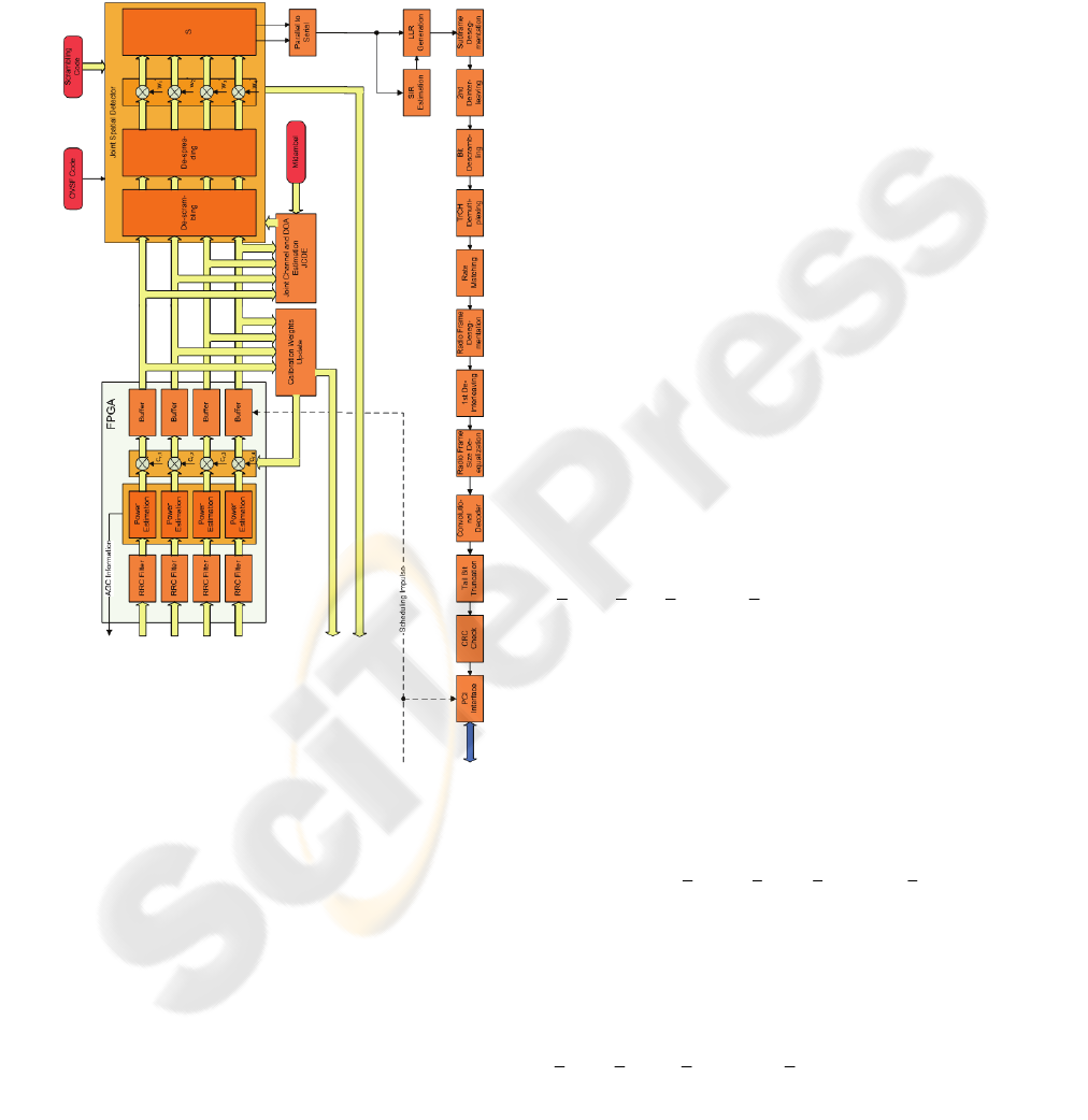
The block diagram for the Node B transmitter is
given in figure 4. The speech data coming from the
PCI interface are first processed in a standard way as
described in (3GPP TS 25.222 V5.2.0, 2002),
(3GPP TS 25.223 V5.1.0, 2002). The subframes
generated by the subframe assembler are multiplied
with the beamforming weights
a
k
w ,
a
14k
=
,
which have been generated by the receiver for the
previous burst. These weights are used to generate
the desired radiation pattern in transmit direction. In
order to overcome inhomogeneities in the transmit
paths the signals are also subject to calibration by
applying calibration weights
a
r,k
c prior to RRC
filtering. Then the signals are passed to the RF
(Radio Frequency) frontend and radiated by the
antenna elements.
The block diagram of the Node B receiver is shown
in figure 5. The signals coming from the RF
frontends are calibrated by appropriate calibration
weights
a
r,k
c ,
a
14k
=
after RRC filtering. The
calibration weights are determined from the
previous burst and updated with each burst. The
calibrated signals are used for channel estimation
and data detection. For channel estimation the Joint
Channel and DOA Estimation (JCDE) block is
responsible. This block determines the DCIR and
provides it to the Joint Spatial Detector (JSD). With
the help of the DCIR the JSD detects the transmitted
data symbols and determines also the beamforming
weights. These are transferred to the transmitter. The
detected symbols are used to generate Log
?SMART ANTENNAS IN UMTS LCR-TDD - Implementation of RSS Beamforming
181
Likelihood Ratios (LLR), which are used for the
further signal processing according to (3GPP TS
25.222 V5.2.0, 2002), (3GPP TS 25.223 V5.1.0,
2002).
For the digital baseband signal processing Harrier
boards from MangoDSP are considered for the Node
B as well as for the UE. Each Harrier board provides
15 TI C6416 DSPs (Digital Signal Processor), five
Altera Stratix FPGAs (Field Programmable Gate
Array), four MangoLink connectors, and a PCI
interface. The 15 DSPs are arranged in five clusters
with three DSPs each. Each DSP cluster is
associated with an FPGA. The FPGAs may be used
for digital signal processing, which requires simple
operations at high sample rates. The FPGAs can also
be programmed to connect the DSPs with each
other. Furthermore, the FPGAs are required for
operating the MangoLink connectors. There is also a
hierarchical system of PCI busses. These allow the
DSPs to communicate with each other and with any
device attached to the external PCI interface.
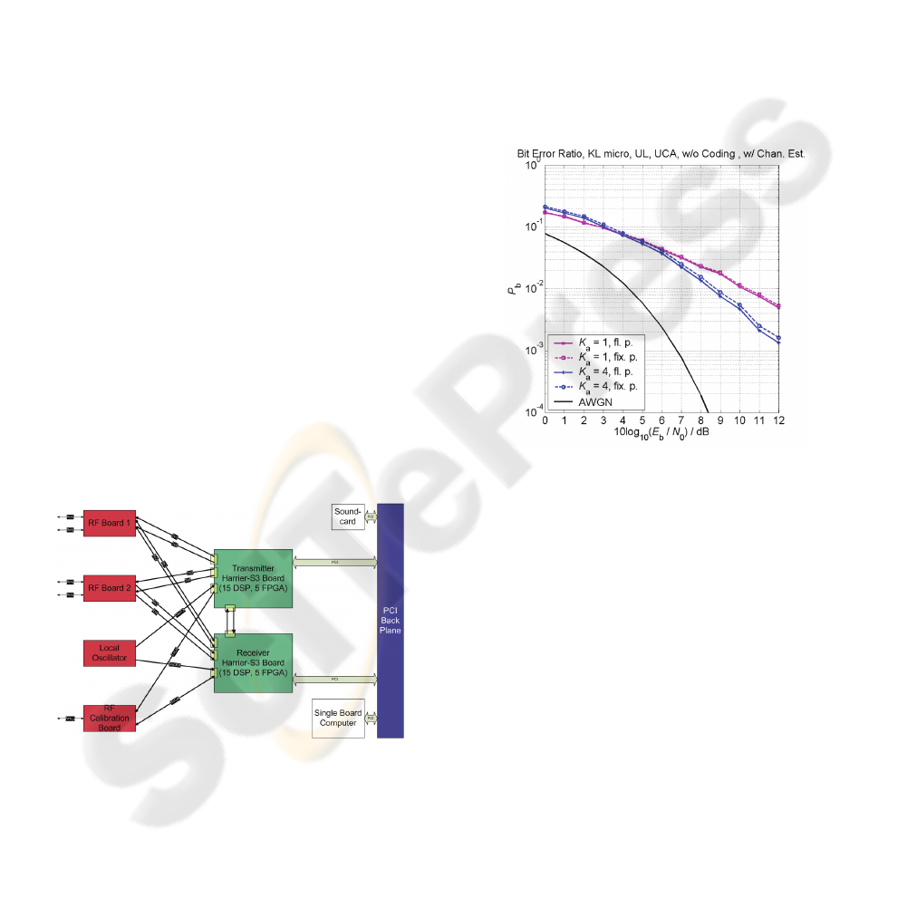
Figure 6 shows the board diagram of the Node B.
The heart of the Node B are two Harrier boards, one
for the transmitter and one for the receiver,
respectively. Each of these Harrier boards is
connected with the two RF boards, which provide
the RF frontend for two antenna elements each.
There is an additional RF board which is used to
operate a single calibration antenna element, which
is required to calibrate the receive paths of the four
RF frontends. The board named “Local Oscillator”
is used to provide a system wide stable clock which
is required for the exact timing.
Figure 6: Board diagram for the Node B.
Figure 6 shows the board diagram of the Node B.
The heart of the Node B are two Harrier boards, one
for the transmitter and one for the receiver,
respectively. Each of these Harrier boards is
connected with the two RF boards, which provide
the RF frontend for two antenna elements each.
There is an additional RF board which is used to
operate a single calibration antenna element, which
is required to calibrate the receive paths of the four
RF frontends. The board named “Local Oscillator”
is used to provide a system wide stable clock which
is required for the exact timing.
The total system is implemented in a 19” rack which
also has a PCI backplane.Besides the two Harrier
boards a Single Board Computer (SBC) and a sound
card are also attached to the PCI backplane. The
SBC is used to control the whole setup and also for
the multirate adaptive speech codec, while the sound
card is used for speech input and output. However,
in order to allow undisturbed real-time
communications the Harrier boards are also
connected by MangoLinks.
Figure 7: Comparison of the fixed-point implementation
with the floating-point implementation.
In order to distribute the identified functions on the
DSPs the complexity of each functional block is
estimated in terms of Mega Instructions Per Second
(MIPS). Implementation guidelines are to implement
as many functions on DSPs as possible in order to
be as flexible as possible. Hence, only rather simple
functions running at high sample rates are
implemented on the FPGAs. Moreover, as few as
possible DSPs shall be used to keep the overall
complexity moderate. Furthermore, the total
estimated load of the DSPs shall be below the
theoretical maximum of the DSPs keeping a
relatively large margin. This analysis reveals that the
Node B transmitter can be realized largely on a
single DSP. Only the weighting with the calibration
and beamforming weights and the RRC filtering is
performed in the FPGA. The total load of the DSP is
then 8.9526 MIPS (Seebens et al., 2005).
The Node B receiver is much more complex than the
WINSYS 2006 - INTERNATIONAL CONFERENCE ON WIRELESS INFORMATION NETWORKS AND SYSTEMS
182

Node B transmitter and requires three DSPs and one
FPGA for implementation (Seebens et al., 2005).
The FPGA is needed for the RRC filtering and the
application of the calibration weights on the
received data. Note, that in the Node B receiver, the
application of the beamforming weights is
performed in the JSD (Seebens et al., 2005). DSP 1
is used for the channel estimation, power estimation,
and calculation of the calibration weights. The total
load of this DSP with the mentioned functions is
estimated to be 61,008 MIPS (Seebens et al., 2005).
Since the JSD is the most complex function of the
receiver, it requires a DSP more or less on its own.
Only minor functions like parallel-to-serial
multiplexing, SIR (Signal-to-Interference Ratio)
estimation and LLR generation are also located on
this DSP. The load of DSP 2 is estimated to be
1583.2884 MIPS (Seebens et al., 2005). The
remaining functions according to (3GPP TS 25.222
V5.2.0, 2002), (3GPP TS 25.223 V5.1.0, 2002) are
implemented in DSP 3 (Seebens et al., 2005). The
total load of this DSP is estimated to be 51.6948
MIPS (Seebens et al., 2005). However, this load can
be further reduced by using the internal Viterbi
Coprocessor of the TI C6416 DSP.
5 SIMULATION RESULTS
In (Seebens et al., 2004), (Scholand et al., 2004)
Matched Filter Bounds (MFB) were simulated to
investigate the performance of the RSS beamformer
in the uplink transmission direction. MFBs provide a
lower limit for the achievable Bit Error Ratio (BER),
that one can expect from an algorithm. The
respective MFBs were obtained by considering a
spatial mobile channel as described in (Scholand et
al., 2004), (
Blanz and Jung, 1998). In (Seebens et al.,
2004), (Scholand et al., 2004) it has been shown,
that the RSS beamformer outperforms the
conventional beamformer by comparing the MFBs.
A comparison between the MFBs in (Seebens et al.,
2004), (Jung, 2004) and link-level simulation results
for a microcellular channel model is given in
(Seebens et al., 2005). For the link-level simulations,
the baseband signal processing according to (3GPP
TS 25.222 V5.2.0, 2002), (3GPP TS 25.223 V5.1.0,
2002) was implemented in the UE transmitter. In the
Node B receiver the functional blocks for the
baseband signal processing were implemented as
given in figure 5. Especially, the channel estimation
and the data detection were performed by using (9)
and (13) with the noise covariance matrices assumed
to be the identity matrices. In (Seebens et al., 2005)
it was shown, that the implementation loss for a
UCA with
a
4K
=
antenna elements at a BER of
3
10
−
is about 1.4 dB. This degradation is due to
imperfect channel estimation and data detection. It
should be noted, that the implementation loss of 1.4
dB is a promising result, since the MFBs represent
the best possible performance one can expect.
For the link-level simulations in (Seebens et al.,
2005) a floating point implementation of the
simulator was considered. According to the selected
hardware all functional blocks on the DSPs and
FPGAs of the demonstrator have to run in a fixed-
point implementation. For further validation, a
fixed-point implementation of the simulator is used
to find limitations and degradations of the fixed
point implementation. The functional blocks realized
in fixed point can then be transferred directly to the
demonstrator hardware.
Figure 7 depicts a comparison of the fixed-point
implementation with the floating-point
implementation of the simulator for
a
1, 4K = antenna
elements. For the simulations the microcellular
channel model in (Scholand et al., 2004), (Blanz and
Jung, 1998) was considered. In accordance to the
simulations in (Seebens et al., 2005) the uplink
transmission was considered, where a single user
was placed randomly in the environment for each
simulation run. For a given signal to noise ratio
(
)
10 b
0
10log EN
a total of 1000 simulation runs were
considered. At each simulation run 100 bursts as
shown in figure 3 were transmitted. With QPSK
modulation and a spreading factor of eight a total of
17.6 Mio. bits were transmitted for each signal-to-
noise value. For the fixed-point implementation a 16
bit quantization was used. This means that the input
and the output of each arithmetic operation are
fixed-point values with a word length of 16 bit.
However, intermediate results may require more bits
and have to be scaled appropriately.
In figure 7 the abbreviations “fl. p.” and “fix. p.”
stand for floating point and fixed point, respectively,
distinguished by solid and dashed lines. The violet
and the blue curves represent the BER for
a
1K
=
and
a
4K
=
antenna elements, respectively. From
figure 7 it can be observed, that the performance of
the fixed-point implementation is slightly worse than
that of the floating-point implementation for
a
1K
=
and
a
4K
=
antenna elements, respectively. For a
UCA with
a
4K
=
antenna elements the performance
degradation of the fixed-point implementation with
respect to the floating-point implementation at a
?SMART ANTENNAS IN UMTS LCR-TDD - Implementation of RSS Beamforming
183

BER of
2
10
−
is only about 0.2 dB.
6 CONCLUSIONS
In this communication an overview of a novel low-
cost beamforming concept based on regularly spatial
sampling of signals is presented. The performance
of the RSS beamforming is investigated by means of
simulations with respect to the LCR-TDD mode of
UMTS. It has been demonstrated, that the RSS
beamformer shows promising performance in terms
of bit error ratios. Moreover, a robust fixed-point
implementation of the RSS beamforming is
presented. For further validation of the performance
of the RSS beamformer, an implementation concept
for a demonstrator is developed in order to show the
feasibility of implementing RSS beamforming on
today’s readily available hardware platforms. It has
been shown, that the total digital baseband signal
processing in the Node B receiver can be
implemented on three standard DSPs.
ACKNOWLEDGEMENTS
The authors wish to thank SAMSUNG Electronics,
Global Standards and Strategy (GSR) for their
generous support. Finally, they gratefully
acknowledge the support of their colleagues.
REFERENCES
Holma, H.; Toskala, A.: WCDMA for UMTS. Second
Edition, Chichester: John Wiley & Sons, 2002.
Lehne, P.H.; Pettersen, M.: An Overview of Smart
Antenna Technology for Mobile Communications
Systems.
IEEE Communication Surveys, vol. 2 (1999),
pp. 2-13.
Correia, L.M.:
Wireless Flexible Personalised
Communications
. Chichester: John Wiley & Sons
Ltd., 2001.
Paulraj, A.; Roy, R.; Kailath, T.: ESPRIT – a subspace
rotation approach to signal parameter estimation.
Proceedings of the IEEE. vol. 74 (1986), pp. 1044 –
1045.
Seebens, A.; Hessamian-Alinejad, A.; Kim, S.H.;
Scholand, T.; Jung, P.: Low-Cost Exploitation of
Spatial Diversity – Regular Spatial Sampling (RSS)
Beamforming.
COoperation européenne dans le
domaine de la recherche Scientifique et Technique
(COST) 273
, 11th Meeting of the Management
Committee, Duisburg, Germany, 2004.
Scholand, T.; Kim, S. H.; Hessamian-Alinejad, A.;
Seebens, A.; Jung, P.: Regular spatial sampling (RSS)
beamforming for the low-cost exploitation of spatial
diversity.
Proceeedings of the Third IASTED
International Conference on Communications,
Internet and Information Technology (CIIT 2004)
, St.
Thomas, US Virgin Islands, 2004, pp. 437 – 442.
3GPP TS 25.221 V5.2.0 (2002-09):
Physical Channels
and Mapping of Transport Channels onto Physical
Channels (TDD)
, Release 5, 2002.
Steiner, B.; Jung, P.: Optimum and suboptimum channel
estimation for the uplink of CDMA mobile radio
systems with joint detection.
European Transactions
on Telecommunications (ETT)
, vol. 5 (1994), pp. 39-
50.
Seebens, A.; Ann, J.; Hessamian-Alinejad, A.; Burnic, A.;
Lee, E.; Scholand, T.; Jung, P.: Performance of RSS
Beamforming for TD-SCDMA Transceibvers.
Proceedings of the Third IASTED International
Conference on Communications and Computer
Networks (CCN 2005)
, Marina del Rey, CA, USA,
2005.
Lu, Y.:
Contributions to the application of adaptive
antennas and CDMA code pooling in the TD-CDMA
downlink
. Ph.D. Dissertation, Universität
Kaiserslautern, (2002), http://kluedo.ub.uni-
kl.de/volltexte/2002/1290/pdf/dissertation_7.pdf.
Godara, L. C.: Application of Antenna Arrays to Mobile
Communications, Part II: Beam-Forming and
Direction-of-Arrival Considerations.
Proceedings of
the IEEE
, vol. 85 (1997), pp. 1195 – 1245.
3GPP TS 25.222 V5.2.0:
Technical Specification;
Multiplexing and channel coding (TDD)
. Release 5,
2002.
3GPP TS 25.223 V5.1.0:
Technical Specification;
Spreading and modulation (TDD)
. Release 5, 2002.
Seebens, A.; Hessamian-Alinejad, A.; Burnic, A.; Jeong,
K.Y.; Scholand, T.; Lee, H.W.; Jung, P.:
Implementation Concept of a LCR-TDD Node B with
RSS Beamforming Capabilities.
Proceedings of the
Third IASTED International Conference on
Communications and Computer Networks (CCN
2005)
, Marina del Rey, CA, USA, 2005.
Blanz, J. J.; Jung, P.: A flexibly configurable spatial
model for mobile radio channels.
IEEE Transactions
on Communications
, vol. 46 (1998), pp. 367 – 371.
WINSYS 2006 - INTERNATIONAL CONFERENCE ON WIRELESS INFORMATION NETWORKS AND SYSTEMS
184
