
A TRANSCEIVER CONCEPT BASED ON A SOFTWARE
DEFINED RADIO APPROACH
Admir Burnic, Alex Vießmann, Tobias Scholand, Arjang Hessamian-Alinejad,
Guido H. Bruck and Peter Jung
Lehrstuhl für KommunikationsTechnik, Universität Duisburg-Essen, 47048 Duisburg, Germany
Keywords: Demonstrator, Digital Signal Processor (DSP), FALCON, Log-Likelihood Ratio (LLR), Reconfigurability,
Software Defined Radio (SDR).
Abstract: In this communication, a software defined radio (SDR) transceiver design, termed FALCON, will be
presented. The FALCON is entirely based on a modular signal processing concept; the FALCON receiver
uses modules which process and generate log-likelihood ratio (LLR) signals, hence, providing the
capability of a plug-and-play-type re-configurability. The authors’ view on re-configurability will be
discussed in this communication. The FALCON currently deploys commercial radio frequency (RF) front-
ends provided by Atmel, analogue and interface boards developed and implemented by the authors and DSP
Starter Kits (DSK) based on TI TMS320C6416 DSPs (digital signal processors), which have been provided
by Texas Instruments. The hardware/software integration has been done in the laboratory of the authors.
Furthermore, the authors developed all signal processing modules in C language tailored for the
TMS320C6416 DSPs. This paper will also illustrate measurement results obtained with the FALCON will
be given. For an easy comparison of these results with widely published simulation results the authors will
consider UMTS/W-CDMA. It will be shown that the FALCON provides a superb performance.
1 INTRODUCTION
Reconfigurability for transceivers for wireless
access networks like Bluetooth, WiMAX
(Worldwide Interoperability for Microwave Access)
and W-LANs will become increasingly important in
the forthcoming decade. Appropriately flexible and
reliable hardware/software architectures, allowing
the concurrent processing of different controlling
tasks for wireless terminals will hence be important
assets. The deployment of communication systems
strongly depends on the availability of appropriate
microelectronics. Therefore, the combined approach
to communication and microelectronic system
design is crucial (Grass et al., 2001). The coming
world of mobile communication will change
dramatically in the future. Wireless networks will
evolve their limited set of services to a great variety
of applications, and the today’s set of wireless
terminal types will expand considerably (Grass et
al., 2001), (Jondral, 2005). A single homogeneous
network like UMTS (Universal Mobile
Telecommunications System) will not provide such
versatile services alone. Only a heterogeneous
network consisting of wired and wireless networks
will form a catalyst for the evolution of such a
diverse mobile world. Future mobile radio
communication systems will hierarchically integrate
a broad variety of wireless networks into a common
structure encompassing e.g. WCDMA-based cellular
mobile systems, OFDM-based radio LANs like
IEEE 802.11a/b, and inexpensive personal-area
networks like Bluetooth. It is recommendable to
establish software defined radio (SDR) and
cognitive radio (CR) concepts in wireless
transceivers.
Reconfigurability in radio development is not a
very new technique (Jondral, 2005). Already during
the 1980s reconfigurable receivers were developed
for radio intelligence in the short wave range.
However, reconfigurability became familiar to many
radio developers with the publication of the special
issues on software radios of the IEEE
26
Burnic A., Vießmann A., Scholand T., Hessamian-Alinejad A., H. Bruck G. and Jung P. (2006).
A TRANSCEIVER CONCEPT BASED ON A SOFTWARE DEFINED RADIO APPROACH.
In Proceedings of the International Conference on Wireless Information Networks and Systems, pages 26-33
Copyright
c
SciTePress
Communication Magazine (Special Issue on
Software Radio, vol. 33, 1995), (Special Issue on
globalization of software radio, vol. 37, 1999).
In (Jondral, 2005) the author refers to a
transceiver as a software radio (SR), if its
communication functions are realized as programs
running on a suitable processor. An ideal SR
directly samples the antenna output which does not
seem feasible w.r.t. e.g power consumption and
linearity as well as resolution requirements on
analog-to-digital converters (ADCs). A software
defined radio (SDR), however, is a practical and
realizable version of an SR: The received signals are
sampled after a suitable band selection filter, usually
in the base band or a low intermediate frequency
band (Jondral, 2005).
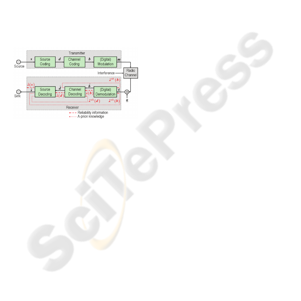
Figure 1: Basic discrete-time structure of a digital radio
communications system with a modular iterative receiver,
cf. (Faber, 2005), Fig. 1.4, p. 11.
In many available publications such as e.g.
(Srikanteswara et al., 2000), (Glossner et al., 2003),
more or less inflexible implementation platforms or
hardware oriented processing architectures for the
control unit have been discussed rather than the
software architecture and real-time operation of
reliable reconfiguration. In (Drew et al., 2001),
(Hoffmeyer et al., 2004) the basic idea of
reconfiguration in a wireless environment was
addressed. However, the authors discussed
procedures which are relevant to the network and
the negotiation process for the updating. The
hardware/software architecture and processing
schemes inside terminals has not yet been
considered in detail.
In order to obtain a flexible radio terminal, the
modular receiver design is a viable asset. In
particular, the physical layer (PHY) modules require
inputs and outputs which facilitate a plug-and-play-
type deployment. Devising PHY receiver modules
which accept, process and generate log-likelihood
ratios (LLRs) is a desirable approach because of the
potential to implement optimum or near-optimum
receiver strategies.
The concept of LLRs in receivers has been
introduced in text-books already in the early 1970s,
cf. e.g. Sect. 5.2, pp. 126ff. of (Whalen, 1971). It
has been applied to e.g. demodulators, see e.g.
(Whalen, 1971), (Chui, 2005), channel decoders, cf.
e.g. (Hagenauer et al., 1994), and joint source-
channel decoding (JSCD), see e.g. (Hagenauer,
1995), (Jung, 1997). However, the aforementioned
publications do not consider implementation issues
in an SDR context. Publications like (Grass et al.,
2001), (Jondral, 2005), (Srikanteswara et al., 2000),
(Glossner et al., 2003), (Drew et al., 2001),
(Hoffmeyer et al., 2004), focusing on SDRs, have
not yet dealt with LLR based receiver realizations.
Such receiver realizations are seldom and usually
consider only parts of the receiver, often the channel
decoder, cf. e.g. (Montorsi et al., 2001), (Faber et
al., 2004)).
The manuscript is organized as follows. The
transmitter and receiver concepts deployed by the
authors shall be briefly described in Sect. 2. The
authors shall discuss their approach to the
reconfiguarbility in Sect. 3. The FALCON setup
implemented by the authors shall be discussed in
Sect. 4. The measurement results obtained with the
FALCON will be summarized in Sect. 5. Sect. 6
concludes the manuscript.
In what follows, the matrix-vector notation is
used. Matrices are denoted as upper case characters
in bold face italics, vectors are lower case characters
in bold face italics. Furthermore, complex-valued
variables are underlined.
2 LLR BASED RECEIVER
CONCEPT
To the best knowledge of the authors, a complete
view on LLR based receiver design and realization
including iterative detection has first been given in
(Faber, 2005), cf. e.g. Sect. 1.2, pp. 9ff. The basic
discrete-time structure of a digital radio
communications system with a modular iterative
receiver is depicted in figure 1 in the case of a single
transmitter and a single receiver and baseband
modeling, cf. (Faber, 2005), Fig. 1.4, p. 11. Other
signal sources are considered as interference. The
source generates the information signal to be
transmitted.
In figure 1, we assume a digital source signal,
represented by the vector
s . The transmitter
A TRANSCEIVER CONCEPT BASED ON A SOFTWARE DEFINED RADIO APPROACH
27
consists of a source encoder, a channel encoder and
a modulator. The source encoder encodes
s and
outputs the binary data vector
d
which is the basis
for the channel coding, generating the binary
channel encoded vector
b . The channel encoder can
e.g. be a turbo-code encoder as it is the case in many
UMTS (universal mobile telecommunications
system) services. The modulator puts out the
complex modulated signal
m , the underline
denoting a complex baseband signal which is then
transmitted via the radio channel.
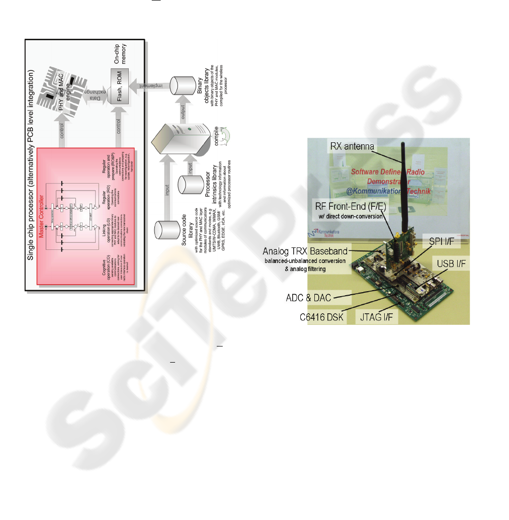
Figure 2: Concept of the Master Controller for reliable
reconfiguration of CRs.
At the input of the receiver, the noise vector
n
is
added, forming the received vector
e . The receiver
inverts the transmitter operations and it therefore
consists of a demodulator, a channel decoder and a
source decoder. The receiver can be operated in a
feed-forward manner as it was e.g. used in
(Montorsi et al., 2001) in the case of a simple single-
path AWGN (additive white Gaussian noise)
channel without any fading. In this case, the
demodulator generates the detected version
b of b ,
together with corresponding exact or approximate
LLR values contained in the reliability information
vector
()
λ b , both being processed by the channel
decoder. The channel decoder puts out the detected
data vector
d
and the reliability information vector
(
)
λ d which consists of the corresponding exact or
approximate LLR values. Then, the source decoder
delivers the detected source vector
s
to the sink.
Also, the source decoder can put out the reliability
information vector
(
)
λ s with the LLR values of s ,
which are not further needed in the further
description.
The shown receiver can also be used in an
iterative mode of operation when the channel
decoder generates the a-priori knowledge estimate
vector
(
)
a,K
λ b which can be used in the
demodulation process. Also, the source decoder can
be devised to produce a-priori knowledge estimate
vectors
(
)
a,Q
λ b and
(
)
a,Q
λ d as further inputs of
the demodulator and of the channel decoder,
respectively.
Figure 3: FALCON transceiver.
In what follows, we will illustrate which PHY
modules of the UMTS terrestrial radio access
(UTRA) FDD (frequency domain duplex) mode W-
CDMA (wideband code division multiple access)
correspond to the channel coding/decoding and the
modulation/demodulation components of the
structure shown in figure 1. The channel coding
component shown in figure 1 consists of the CRC
(cyclic redundancy check) generation, the Turbo
Code encoding with the rate matching, the first
interleaving, the radio frame and the physical
channel segmentation and the second interleaving.
The modulation component contains the pilot
generation, the frame and the slot assembling, the
WINSYS 2006 - INTERNATIONAL CONFERENCE ON WIRELESS INFORMATION NETWORKS AND SYSTEMS
28
serial-to-parallel conversion, the channelization code
generation, the OVSF (orthogonal variable
spreading factor) spreading, the scrambling code
generation and allocation, the complex scrambling,
the primary and secondary synchronization channel
generation, the signal amplification and the signal
summation, the root raised cosine (RRC) filtering,
and the analog transmission section including the RF
(radio frequency) transmit part.
The demodulation component of figure 1 contains
the RF receive part, the RRC filtering, the adaptive
RAKE receiver consisting of a searcher exploiting
the synchronization channels for frame and slot
synchronization as well as channel parameters
identification and RAKE finger allocation, a
variable number of adaptive RAKE fingers
including the channel parameter tracking, the de-
scrambling and the de-spreading, a maximal-ratio
combining (MRC) unit including a signal-to-noise-
and-interference ratio (SNIR) estimation unit, a
parallel-to-serial conversion unit and an LLR
computation unit, and, finally, the frame and the slot
disassembling. The channel decoding component
shown in figure 1 consists of the second de-
interleaving, the radio frame and the physical
channel de-segmentation, the first de-interleaving,
the Turbo Code decoding with the rate de-matching,
and the CRC (cyclic redundancy check) decoding.
Similarly, the mapping of OFDM (orthogonal
frequency division multiplexing) based concepts like
WiMAX IEEE 802.16e can be done.
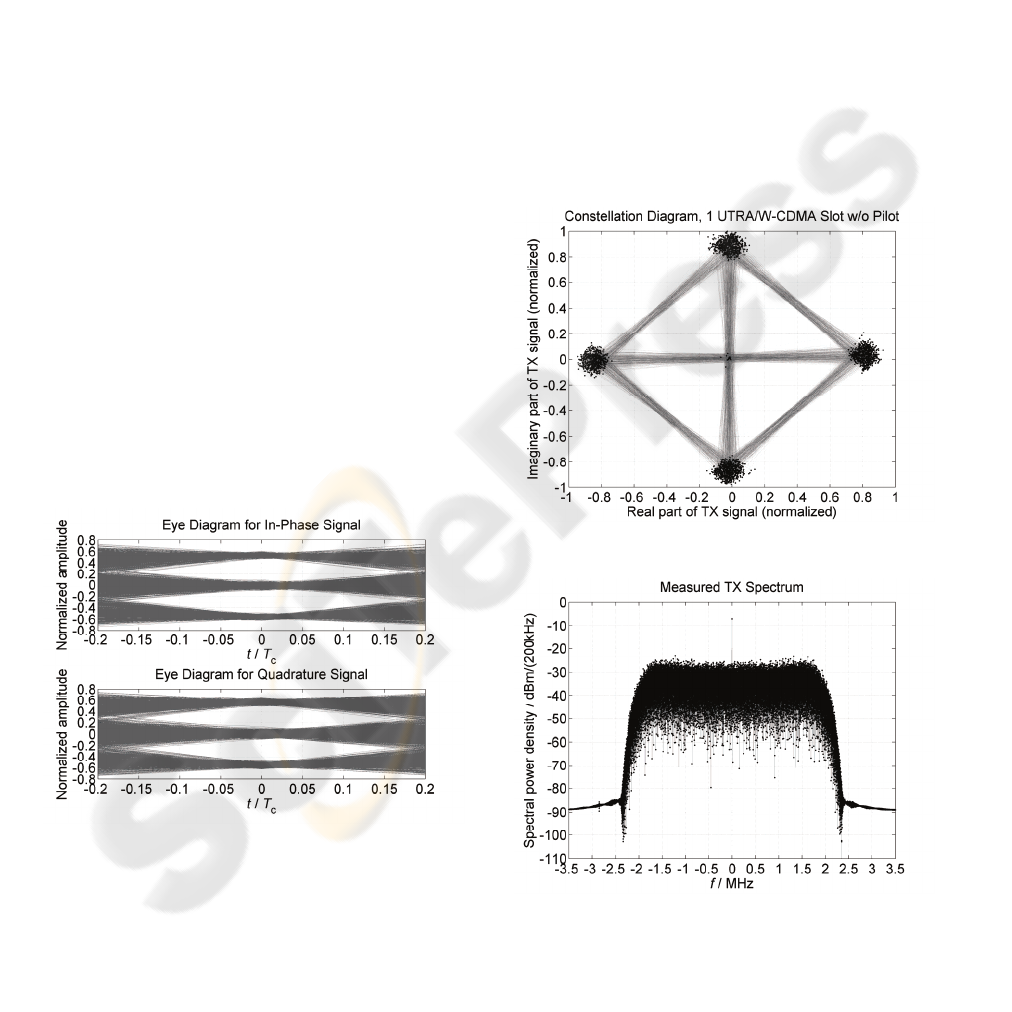
Figure 4: Eye diagrams of the in-phase and quadrature
signals at the input of the radio frequency (RF) board.
3 APPROACH TO THE
RECONFIGURABILITY
In order to achieve a best possible reconfigurability,
the deployment of software definable hardware is
beneficial. In particular, the deployment of digital
signal processors (DSPs) in combination with
dedicated mixed signal hardware which can be
parameterized. In this case the reconfiguration of the
transmitter can be easily accomplished by
implementing e.g. the appropriate PHY signal
processing algorithms mainly in software, allowing
a highly flexible and reliable software architecture
based strategy. This approach has been taken by the
authors and shall be further described in the sequel
of this communication.
Figure 5: Measured transmit constellation diagram.
Figure 6: Measured transmit spectrum.
The transmitter can be reconfigured by using
known programming techniques, by using encoder
A TRANSCEIVER CONCEPT BASED ON A SOFTWARE DEFINED RADIO APPROACH
29
and modulator software modules which can be
parameterized in the anticipated ranges. This has
been a standard strategy which will not be further
considered here.
However, the use of LLR based reliability
information in the receiver seems to be a novel idea;
in particular in combination with iterative receiver
strategies. LLR based reliability information makes
a further re-scaling of soft values unnecessary. This
fact facilitates a particularly simple reconfiguration
of the receiver. When using this approach, single
hardware/software modules can be replaced without
affecting other modules, making the solution “plug-
and-play”.
In a future version of the FALCON, currently
under development, the authors will further improve
the reconfigurability by deploying an additional
ARM controller which will run concurrent
controlling tasks including the reconfiguration
mode. The software architecture has been devised
using Petri nets (PNs) (Murata, 1989), (Reisig,
1985) and paves the way towards cognitive radio
(CR) (Jondral, 2005) concepts.
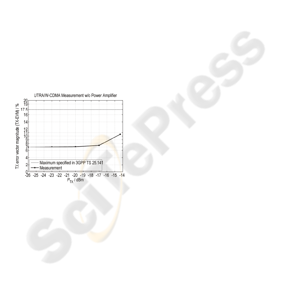
Figure 7: Measured error vector magnitude values at the
transmitter output.
The way of reconfiguration of a terminal, in
particular, the realization of a processor with master
controller and a Petri net based approach, which
allows concurrent mode of operation and high
reliability and secure applications, has not yet been
treated. The new approach proposed by the authors
consists of a Master Controller, which is responsible
for a reliable reconfiguration. In addition, there has
to be a unit, which can communicate with the
network, a PHY and MAC (medium access control
layer) engine. This PHY and MAC engine needs
software modules with signal processing algorithms
for the data processing path. The third part is a
memory, which contains these software modules.
The Master Controller starts a cognitive operation in
order to obtain the best reconfiguration and software
modules needed for the SDR. The reconfiguration
then consists in the linking of software modules,
found in the memory, and installing them into the
SDR to use the software modules in the regular
signal processing chain.
Figure 2 shows the described concept of the
Master Controller for reliable reconfiguration of
CRs. The Master Controller works with the
mentioned PN based software architecture. It needs
a scalable control program which can e.g. be created
by using e.g. Petri net compilers. As already
mentioned, the implementation and validation of the
Master Controller based concept on a PCB level
integration will be done in the FALCON. In real
terminals, an implementation in a single chip
processor is conceivable.
4 THE FALCON SETUP
The FALCON currently consists of two identical
transceivers (TRXs). Figure 3 shows a photograph
of one of these TRXs. Each TRX consists of an RF
front-end board with a single direct-downconversion
RF chip, provided by Atmel, an analog TRX
baseband board with filtering and signal conversion
parts and a SPI (werial peripheral interconnection)
interface for the DSP based programming of the RF
chip, the mixed signal board carrying the ADC
(analog-to-digital converter) and DAC (digital-to-
analog converter) hardware, a USB (universal serial
bus) interface board for the transfer of the
information to the transmitter and of the detected
information to the sink, and a TMS320C6416 DSP
Starter Kit (DSK), provided by Texas Instruments,
with a JTAG (joint test action group) interface for
controlling and programming purposes. The RF
front-end boards can provide transmit power values
ranging from
26 dBm
−
to 14 dBm− without
further power amplification and they have separate
transmit and receive antenna connectors; in Figure
3, only the receive antenna is connected. The
hardware/software integration has been done in the
laboratory of the authors as well as the development
of all the signal processing modules, which have
been realized in C language tailored for the
TMS320C6416 DSPs (digital signal processors).
WINSYS 2006 - INTERNATIONAL CONFERENCE ON WIRELESS INFORMATION NETWORKS AND SYSTEMS
30
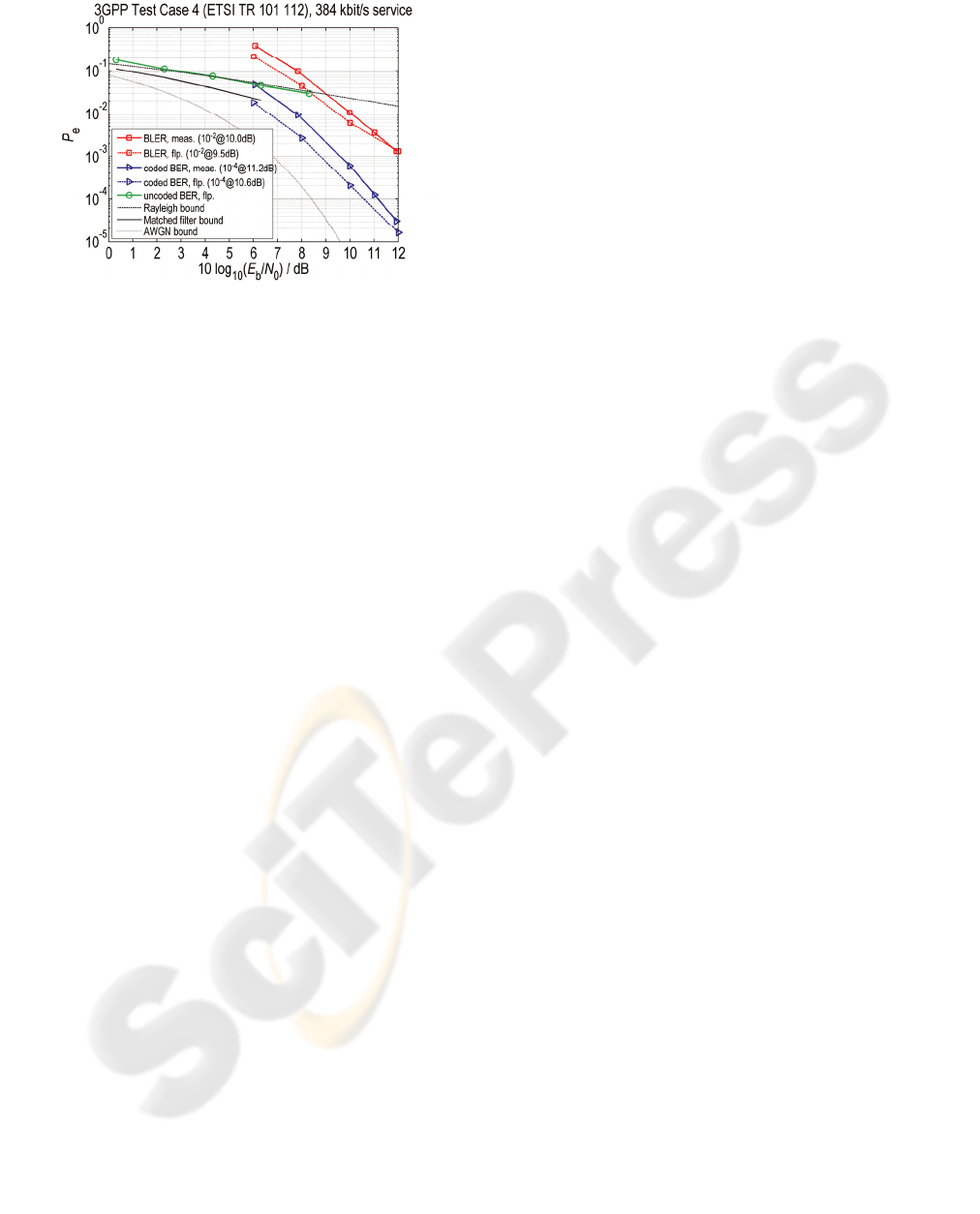
Figure 8: Comparison of performance measurements and
simulation results in the case of the 3GPP Test Case 4
channel model described in ETSI TR 101 112 in the case
of the 384 kbit/s service.
The FALCON has been intended to address mid-
range terminals and access points, in particular for
cellular systems. Its functionality has bee validated
for the UTRA/W-CDMA and OFDM based
concepts like WiMAX IEEE 802.16e in indoor and
laboratory environments with short delay spreads.
The FALCON e.g. provides programmable digital
filtering, automatic frequency correction (AFC) and
adaptive synchronization schemes which
compensate impairments occurring in the analog
domain. Measurements of the signal processing
effort in MIPS (million instructions per second)
have validated the real-time capability of the
FALCON, both software and data fit into the DSP
internal memories. In the case of indoor
environments, a single RAKE finger is sufficient to
provide the desired UTRA FDD performance. In the
case of the UTRA FDD 384 kbit/s service and a 720
MHz version of the TMS320C6416 DSP, the
software implementation used by the authors
consumes approx. 5.7 million processor cycles, the
de-interleaving, rate de-matching and signal
representation conversions require approx. 0.6
million processor cycles, totaling in a DSP load of
about 96%. The remaining DSP capability is
sufficient to accommodate the rest of the receive and
the transmit signal processing.
5 MEASUREMENT RESULTS
In this section, several measurement results obtained
with the FALCON for the UTRA FDD 384 kbit/s
service will be presented. First measurement results
of transmit front-end characteristics will be
considered. Figure 4 shows the eye diagrams of the
in-phase and quadrature signals at the baseband
input of the RF front-end chip and Figure 5 presents
the corresponding constellation diagram. In both
cases, now pilot transmission has been considered
which is the reason for the occurrence of amplitude
values around 0.
The measured transmit spectrum at the input of
the transmit antenna is depicted in figure 6 in the
case of
20 dBm
−
transmit power and the measured
values of the error vector magnitude (EVM) at the
input of the transmit antenna versus the transmit
power is shown in figure 7. The spectrum of figure 6
shows a nice agreement with the spectral mask
required by the UMTS standard, the effect of the
RRC filtering can be clearly observed. According to
figure 7, the EVM is ranges between 7% and 8% for
transmit power values between
26 dBm−
to
17 dBm
−
. Only in the case of high transmit power
values above
17 dBm
−
, the EVM increases to
approximately 10.5%. In all cases the EVM is well
below the maximum allowed EVM of 17.5%,
specified in the UMTS standard.
Figure 8 shows obtained simulation and
measurement results in the case of the UTRA FDD
384 kbit/s service in the case of the transmission
over the 3GPP Test Case 4 channel model which has
been implemented in a channel simulator. The
simulations were carried out with a floating point
implementation of the signal processing algorithms
done in C language. The measurements have been
done with the digital implementation of the
FALCON, the mixed signal and RF parts have not
been considered.
The simulator determines the matched filter BER
bound, which is the best possible performance in the
case of the transmission of isolated bits over the
channel and perfect knowledge of the channel at the
receiver, together with the uncoded BER which can
be obtained when considering the UTRA FDD 384
kbit/s service. The latter is of course worse than the
matched filter bound. Furthermore, the simulator
puts out the BER and the BLER (block error ratio)
at the output of the Turbo-Code decoder. For
reference purposes, we will consider the coded BER
4
10
−
and the coded BLER
2
10
−
, the latter meaning
that 99% of all transmitted blocks have been
received correctly, i.e. the throughput is equal to
99%. In the case of the 3GPP Test Case 4 channel,
we require
10.6 dB
≈
to achieve the coded BER
4
10
−
and 9.5 dB
≈
to obtain the coded BLER
2
10
−
. The fixed point implementation in the
A TRANSCEIVER CONCEPT BASED ON A SOFTWARE DEFINED RADIO APPROACH
31

FALCON leads to a small degradation of
approximately
0.5 dB , and we yield 11.2 dB≈ to
achieve the coded BER
4
10
−
and 10.0 dB≈ to
obtain the coded BLER
2
10
−
.
In figure 8, the theoretical performance bounds of
the BER (bit error ratio) are depicted as a function
of the required signal-to-noise ratio
()
10 b 0
10log
E
N for the single path no fading
(“AWGN bound”) case,
b
e
0
2
E
PQ
N
⎛⎞
=
⎜⎟
⎜⎟
⎝⎠
, (1)
()
Q ⋅ being the Q function, and the single path full
fading (“Rayleigh bound”) case,
b
e
b0
1
1
2
E
P
E
N
⎛⎞
=−
⎜⎟
⎜⎟
+
⎝⎠
(2)
b
E
being the average energy per bit, are depicted
for reference purposes.
In general, we find that the simulated and the
measures performance agree very well.
Measurements of receive front-end characteristics,
such as e.g. the intermodulation distortion (IMD)
and, correspondingly, the effective number of bits
(ENOB), are currently ongoing. Also, measurements
of the BERs and BLERs in the case of the operation
over the air, i.e. including the effects of the mixed
signal and RF parts of the FALCON, are currently
being done. The same accounts for the WiMAX
transceiver operation.
6 CONCLUSIONS
In this communication, the authors presented the
FALCON concept, entirely based on modular signal
processing. The authors showed that the FALCON
receiver deploys modules which process and
generate LLR based reliability information which
plays a key role when targeting reconfigurable
hardware. Furthermore, the authors discussed a
novel concept for the reconfigurability of
transceivers which supports the way towards
cognitive radios.
The FALCON currently deploys commercial
radio frequency (RF) and DSP boards. Furthermore,
it uses mixed signal and interface boards
implemented by the authors. Also, the software
development and the system integration, both
hardware and software, has been done by the
authors.
Finally, the authors presented selected
measurement results obtained in the case of the
UTRA FDD 384 kbit/s service. Further
measurements are currently ongoing. It was shown
that the FALCON provides a desirably performance
and therefore proves that the concept of the
FALCON is viable.
ACKNOWLEDGEMENTS
The authors wish to thank Atmel and Texas
Instruments for their generous support. Furthermore,
the authors are grateful to their colleagues for
valuable support.
REFERENCES
Grass, E.; Tittelbach-Helmrich, K.; Jagdhold, U.; Troya,
A.; Lippert, G.; Kruger, O.; Lehmann, J.; Maharatna,
K.; Dombrowski, K.F.; Fiebig, N.; Kraemer, R.;
Mahonen, P.: On the single-chip implementation of a
hiperlan/2 and IEEE 802.11a capable modem. IEEE
Personal Communications, vol. 8 (2001) no. 6, pp. 48-
57.
Jondral, F.K.: Software-defined radio – basics and
evolution to cognitive radio. EURASIP Journal on
Wireless Communications and Networking, vol. 3
(2005), pp. 275-283, including all references.
Special Issue on software radio. IEEE Communications
Magazine, vol. 33 (1995), no. 5.
Special Issue on globalization of software radio. IEEE
Communications Magazine, vol. 37 (1999), no. 2.
Srikanteswara, S.; Reed, J.H.; Athanas, P.; Boyle, R.: A
soft radio architecture for reconfigurable platforms.
IEEE Communications Magazine, vol. 38 (2000), no.
2, pp. 140–147.
Glossner, J.; Iancu, D.; Lu, J.; Hokenek, E.; Moudgill, M.:
A software-defined communications baseband design.
IEEE Communications Magazine, vol. 41 (2003), no.
1, pp. 120–128.
Drew, N.J.; Dillinger, M.M.: Evolution toward
reconfigurable user equipment. IEEE Communications
Magazine, vol. 39 (2001), no. 2, pp. 158–164.
Hoffmeyer, J.; Park, I.-P.; Majmundar, M.; Blust, S.:
Radio software download for commercial wireless
reconfigurable devices. IEEE Radio Communications
(March 2004), pp. S26–S32.
Whalen, A.D.: Detection of signals in noise. San Diego:
Academic Press, 1971.
Chiu, M.-C.: A low-complexity SISO multiuser detector
for iterative decoding of asynchronous CDMA
systems with convolutional codes. IEEE Transactions
on Vehicular Technology, vol. 54 (2005), pp. 516-524.
WINSYS 2006 - INTERNATIONAL CONFERENCE ON WIRELESS INFORMATION NETWORKS AND SYSTEMS
32

Hagenauer, J.; Robertson, P.; Papke, L.: Iterative ('Turbo')
decoding of systematic convolutional codes with the
MAP and SOVA algorithms. Proceedings of the ITG-
Conference on Source and Channel Coding (SCC'94),
München, pp. 164-172, 1994.
Hagenauer, J.: Source-controlled channel decoding. IEEE
Transactions on Communications, vol. 43 (1995), pp.
2449–2457.
Jung, P.: Analyse und Entwurf digitaler Mobilfunksysteme.
Stuttgart: B.G. Teubner, 1997.
Montorsi, G.; Benedetto, S.: Design of fixed-point
iterative decoders for concatenated codes with
interleavers. IEEE Journal on Selected Areas in
Communications, vol. 19 (2001), pp. 871-882.
Faber, T.; Jung, P.: Digital signal processing complexity
of Turbo-Codes for UMTS on the TMS320C6416.
Proceedings of the IEEE International Conference on
Computers and Devices for Communication
(CODEC’2004), Kalkota/India, January 2004.
Faber, T.: Turbo-Empfänger für digitale
Mobilfunksysteme, gezeigt am Beispiel eines
“Software Defined Radio”-Demonstrators. Series
„Selected Topics in Communications Technologies,“
(edited by Prof. Dr.-Ing. habil. Peter Jung), Aachen:
Shaker, 2005.
Murata, T.: Petri nets: Properties, analysis and
applications. Proceedings of the IEEE, vol. 77 (1989)
no. 4, pp. 541–580.
Reisig, W.: Petri nets: An introduction. Berlin: Springer,
1985.
A TRANSCEIVER CONCEPT BASED ON A SOFTWARE DEFINED RADIO APPROACH
33
