
USING A DEPTH TREE FRAMEWORK TO EVALUATE
CHANGE IMPACTS OF MODIFICATIONS TO IT
INFRASTRUCTURE
Yang Min
1
, Zhang Mi
2
, Han Peng
3
, Chen Haiguang
4
, Zhou Xi
5
, Mao Dilin
6
, Gao Chuanshan
7
1,2,3,4,5,6,7
Department of Computer Science and Engineering, Fudan University, Shanghai, P.R.C, 200433
Keywords: Depth Tree Change IT Infrastructure.
Abstract: In a business IT system, change is an engine of progress, as well as a source of doom. End user applications,
operational disciplines, and IT vendors are major sources of continuous change. However, application
software change control is a relatively mature process; many organizations implement IT infrastructure
change manually, relying primarily on the IT staff's knowledge and expertise. Thus, an effective and
efficient way to settle it is urgently needed. In this paper, we take a necessary first step toward the change
management of IT infrastructure. Mainly along with utilizing a depth tree, termed with DTM in the
following, to qualitatively get hold of the sequence of affected parts of IT infrastructure and trace the
detailed propagation paths, it can also be relatively accurate to evaluate the quantitative influence to each
implicative part and provide its benchmark-values corresponding to industrial experiences in business and
techniques for the decision-makers.
1 INTRODUCTION
IT Infrastructure Change Management is primarily
driven by increasing business requirements
especially in recent years (Jean-Pierre Garbani,
2004). However, application software change
control is a relatively mature process; many
organizations implement infrastructure change
manually, relying primarily on the IT staff's
knowledge and expertise.
The industry is focused on how the infrastructure
reacts to that change while each corporation has its
unique system for each own business process. That’s
why ITIL (IT Infrastructure Library) is developed,
which is a framework of an integrated set of
processes that are designed to provide best practice
in the support and delivery of IT services, while
change management framework can be defined as
that integrated set of processes, standards and
supporting tools that facilitate the management of
the application of changes to IT Infrastructure (Mark
Nicolett,Debra Curtis,2002). But it is only the
guidance on the process of change management
rather than the total solution on this problem, even
not a methodology dealing with it.
Meanwhile, companies need a methodology to
analysis the propagation progress of Change Impact
qualitatively and quantitatively. Also, it should be
able to produce the sequence of the affected parts of
IT infrastructure and trace how change ripples
corresponding to the process of change impacting
propagation as well as to calculate the impact more
accurately than that envisioned.
The rest of this paper is organized like this:
section 2 presents the related work and endeavor
both in the academy and the industry; section 3
offers the formulation models of IT Infrastructure
with the help of ADS and algorithms using
dependency analysis to construct the depth tree;
section 4 addresses our conclusion and the future
work.
2 RELATED WORK
According to ITIL (Colin Rudd,2004), a single
centralized Change Management process, for the
efficient and effective handling of changes, is vital
to the successful operation of any IT organization.
Changes must be carefully managed throughout their
entire lifecycle from initiation and recording,
88
Min Y., Mi Z., Peng H., Haiguang C., Xi Z., Dilin M. and Chuanshan G. (2006).
USING A DEPTH TREE FRAMEWORK TO EVALUATE CHANGE IMPACTS OF MODIFICATIONS TO IT INFRASTRUCTURE.
In Proceedings of the International Conference on e-Business, pages 88-92
DOI: 10.5220/0001427000880092
Copyright
c
SciTePress
through filtering, assessment, categorization,
authorization, scheduling, building, testing,
implementation and eventually their review and
closure. The kernel issue of change management of
IT infrastructure is to assess the impact of a
proposed change in the entire system and to evaluate
the benefits and costs on the initial and consequent
modifications. In industry, there are several leading
companies, such as IBM, HP, Remedy, CA, etc, are
hammering at this issue. The gap between business
requirements and IT services is the big challenge
that it is hard to describe the hand-on consequence
because of the change.
Nevertheless, in academy, as commonly believes,
traditional impact analysis approaches based on
program slicing (M.Weiser,1984) (S.
Horwitz,T.Reps, etc,1993) and program dependence
graphs(R.Al-Zoubi and A.Prakash,1995) (J.Loyall,
etc,1993)(A.Podgurski, etc,1990). And almost all of
these works were studied in the context of
conventional programming language, while fewer
focused on the IT infrastructure especially in recent
years. According to Zhao (Jianjun Zhao,1997), most
of the results presented above are derived from the
study of small commercial systems or even of
systems developed in course assignments instead of
the realistic IT environment. So, the existing
academic methods need further work to apply to real
large-scale system because of the different
characteristics. IT infrastructure contains
complicated mixtures of software and hardware and
anfractuous relationships while these academic
works would rather engage in the hierarchy
relationships between interfaces or classes in a
program/application. (Jun Han,1997) (M.Ajmal,
etc,1999) (Jianjun Zhao,1997) may allow for the
software architecture in the software engineering
environment, and they all made great efforts to
analysis the dependences in software architecture,
which give the hints to evaluate change impact. All
these works focus on the impact relationship
analysis, but do not evaluate the quantitative
influence to each part of software architecture
indeed because the model they used can only
represent the qualitative relationships. Thereby, a
model to describe the implicative parts elaborately is
necessary that the rippling effect spreading abroad in
a quantitative manner among the IT infrastructure
can be evaluated. Meanwhile, the model would help
to leverage the gap between the business
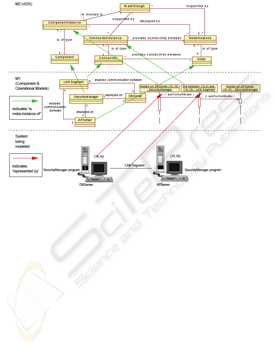
Figure 1: ADS-View of a scrap of the sample IT infrastructure.
USING A DEPTH TREE FRAMEWORK TO EVALUATE CHANGE IMPACTS OF MODIFICATIONS TO IT
INFRASTRUCTURE
89
requirement and IT service and formalize the
propagation by abstracting the invoking
relationships between different business functional
operations as will be descried in section 3.
3 DTM: ELEMENTARY
METHODOLOGY TO
EVALUATE CHANGE IMPACT
OF IT INFRASTRUCTURE
3.1 Modeling IT Infrastructure in
DTM
3.1.1 General Architecture Description
Standard - ADS
The complicated IT infrastructure is composed of
numerous applications, middlewares, operating
systems, mainframes, servers, LAN devices, etc.
ADS (Ed Kahan,2005) is initiated to take advantage
of the industry experiences gained over the last few
years exploration. The semantic specification aims
to provide the clear and unambiguous definition of
the concepts involved in modeling certain aspects of
the architecture of IT system.
As figure 1 intercepted from (Ed Kahan,2005)
shows, a commonly accepted structure for
metamodeling is the four layer metamodel hierarchy,
on which among UML is based. According to ADS:
Infrastructure: the system being modeled.
M1 layer: this layer contains the concepts that
represent things from the system being modeled. It is
referenced to as a model layer.
M2 layer: this layer contains the meta-concepts.
All models are built from instances of these meat-
concepts. This layer is referenced to as a metamodel
layer.
M3 layer: this layer contains the meta-meta
concepts. All metamodels are built from instances of
these meta-meta concepts. It is referenced to as a
meta-metamodel layer.
With this specification, we can accurately abstract
and model the infrastructure according to the
algorithm through finely defining each functional
sub-system as well as its dependency relationships
and its attributes, just illustrated as figure 2.
3.1.2 The Formulation Model of IT
Infrastructure
In this section, we will formulize the IT
infrastructure with the following rules so that DTM
can build up a formulation model utilizing ADS, and
then DTM can evaluate the change impact easily and
automaticly throughout the model.
Figure 2: M3 Layer of ADS-view of IT Infrastructure.
Definition 1: Base Functional Unit (BFU)
It is a functional operation, which will serve
others through its specific interface, no matter
whether it is a software unit or hardware unit or
admixture of both. And it will be finely defined at
the beginning of forming ADS-description of the
whole IT infrastructure when modeling, with the
suitable granularity according to the business logic,
which depends on the experiences and skills of the
architect. And it will be mapped into the concepts of
M1 layer, as the figure 1 illustrates.
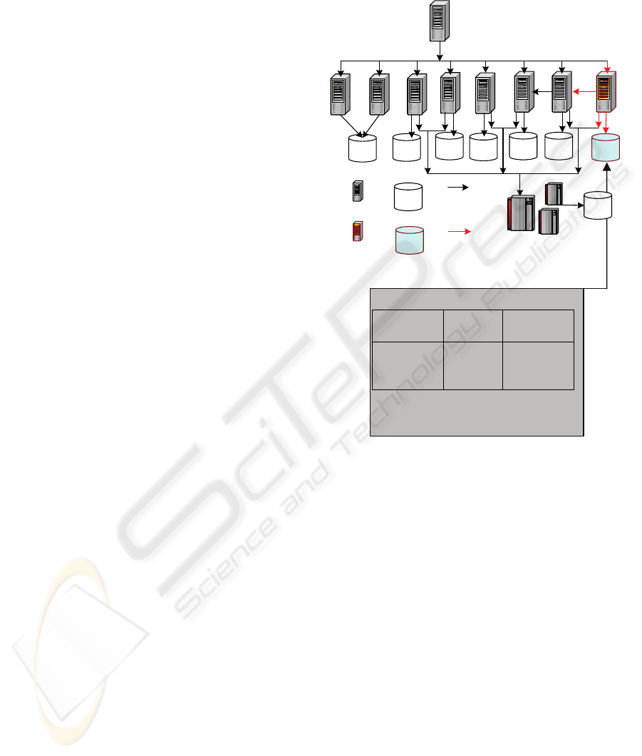
Definition 2: Component
It is a logical entity composed by one or more
functional operations, as figure 3 shows, which
involves: Applications; Subsystem; Mainframe;
Server; Storage; LAN devices; Or Combination
made up of several other components.
Suppose A is a component, then: A={ a
1
, a
2,
a
3
,……, a
n
}, while a
i
is a component either.
The Base Functional Unit (BFU) is regarded as
the atomic component, which means not to be
composed by any other components. As defined in
Business Functional Operation:
Customer
Management
Integrated
Services
Product
Services
System
Management
Integrated
Count
Inquiry
Provider/
Copartner
Management
Com_
GH
Com_F
Com_E
_
Com_
C
Com_
D
Existing
Subsystem
Increased
Subsystem
Existing
Dependency
Increased
Dependency
Existing
DB
Server
Increased
DB
Server
Com_B
Web Component
Com_C
Com_D
Com_E
Com_FCom_GCom_H
Com_A
Com_A
Com_B
Com_I
Com_I
ICE-B 2006 - INTERNATIONAL CONFERENCE ON E-BUSINESS
90
definition 1, each of the six units would not be
decomposed into a smaller granularity.
In this case, we will call a
i
is A’s sub-component
while A is a
i
’s sup-component. A component will be
mapped to the M1 layer. Typically, an order
processing sub-system, including the application
server, os and the hardware server, will be regarded
as a component which may be composed by several
different business operations.
Definition 3: Input and Output of a component
To component A, it will have Input and Output of
a RequestForCapacity, and we describe that as F
in
(A)
and F
out
(A), which will be formed as a n-vector like
{i
1
,i
2
,……,i
n
}. Each one in this vector represents for
one attribute of a business functional operation.
Figure 3: Component.
Input:
It represents the parameters of each business
operation called by the other components. For
example, a typical input for an order processing sub-
system will be like,
Output:
It represents the parameters of the other
components called by its business operation.
Utilizing input and output, implicative components
can build up relationships. When change occurs, the
numerical values of input and output will be updated
according to the rippling sequence, then after the
propagation ends, based on these parameters of
input, the calculation of the benchmark-value, such
as TPmC (Typically Used for a DB server),
SPECjbb (Typically used for applications reside in
an application server), will be relatively accurate
according to the industry experience. The variation
of the capacity of each affected part can be evaluated.
Also, we suppose the parameters have been defined
by ADS at the M1 layer.
ADS would give the specific RequestForCapacity
for each base functional unit as well as for each
component, which represents for the standard Input
and Output. Besides this, they should agree with
following expressions:
F
in
(A)
⊆
∪ F
in
(a
i
), F
out
(A)
⊆
∪ F
out
(a
i
)
When we compose several components, we can
get the Fin and F
out
of the sup-component from F
in
and F
out
of each sub-component according to the
environment.
Assumption:
Each RequestforCapacity of Input and Output of
the components is finely defined as attributes in
ADS-view. Indeed, it’s business-specific. They are
tightly associated to the specific functions of the
components and also they will be defined by the
architect according to the estimative capacity of
design requirements of the correlated components,
such as a vector (total number of users, type of
business operations, percent of each type, response
time, maximum concurrent users, java operations,
number of standard transaction).
Definition 4: Dependency Relationship R:
A R B represents that component A has a direct
influence to component B which means there are
connections between the input and output of these
two components respectively. That is:
A R B = { (a
i
,b
j
) |
∃
(f∈ F
out
(a
i
) ∧ f∈ F
in
(b
j
)), a
i
∈ A,
b
j
∈ B }
If given A, B, C, while
∃
(a,b)
∈
A R B and (b,c)
∈
B R C, then we think that A has a indirect impact
to C. Typically in IT infrastructure, A R B, means
there exists a part of A calling functional services of
some part of B. As an indirect impact, the called
functions of some part of B will need the services of
some part of C while fulfilling A.
3.1.3 The Key Algorithm of DTM
Methodology: Creation of a Depth
Tree
Using the enterprise model, the paper has developed
a methodology named DTM, which takes the
rippling effect of change impact propagation
progress into careful consideration, to analyze the
impact of the change to the whole infrastructure..
Algorithms pseudo-code:
1. Create the Initial Tree T : root
node rt with depth Å0 and its
directly impacting nodes A[1…n] with
each depthÅ1;
2. i Å1
3. CURRENT_NO Å n
4. REPEAT
a) jÅ1
b) WHILE (j<= CURRENT_NO)
i. a
j
Åone of the component at ith
depth
ii. IF(a
j
directly impacting nodes
B[1…m])
USING A DEPTH TREE FRAMEWORK TO EVALUATE CHANGE IMPACTS OF MODIFICATIONS TO IT
INFRASTRUCTURE
91

THEN FOR t Å 1 to m
IF ( B[t]
∉
T )
[Add B[t] to T]
[Set depth of B[t] Å i+1]
ELSE IF !(Check Dependency Loop
from a
j
to B[t])
[Add B[t] to T]
[Update depth of B[t] Å i+1]
[Update depth of B[t]’s sub
tree]
ELSE
[Exit]
iii. j++
c) i++
d) CURRENT_NOÅthe number of
components at the ith depth
5. UNTIL CURRENT_NO = 0
6. RETURN T
4 CONCLUSIONS AND FUTURE
WORK
All of IT Infrastructure Change Management want to
do is about proactive, efficient and effective use of
all its resources for the requirements when changes
occur. In this paper, we present our method named
DTM to cope with the problem that changes to IT
infrastructure bring down on. And also we
implement it to the typical case of IT infrastructure.
The results show that DTM works. It provides
decision-makers with the sequence of affected
components when change occurs and propagates and
the quantitative evaluation of the impact to each
affected components using functional equations
gained from industrial experiences as well. Based on
the result, we can easily know where the critical
point of the infrastructure is when some specific
change should be put into practice and how much
the whole infrastructure is influenced. Thus, we link
up the business requirements and IT services
ingeniously and leverage the gap between them by
abstracting the invoking relationships between
different business functional operations.
In the future, we will implement DTM to some
realistic industry companies and consummate it with
much more calculation equations suitable for
different systems and platforms including varieties
of hardware. Then we will develop a tool to support
automation change managements, especially offer
decision-makers with change plans according to
business requirements and impacts analysis of
change implementation.
ACKNOWLEDGEMENTS
The Conference Participation is supported by Nokia
Bridging the World Program.
REFERENCES
Jean-Pierre Garbani, 2004. Best Practices For
Infrastructure Change Management.
Mark Nicolett, Debra Curtis, October 2002. Enterprise
Management Scenario: Managing the IT Infrastructure
as a Business Service, in Gartner Symposium
ITXPO’02.
Ed Kahan, July 2005. Architecture Description Standard:
Semantic Specification, published by IBM, 3
rd
version.
Colin Rudd, July, 2004. An Introductory Overview of ITIL,
published by itSMF Ltd, pp.17.
M.Weiser, 1984. Program slicing, in IEEE Trans. on
Software Engineering, SE-10(4):352-357.
S. Horwitz, T. Reps, and D. Binkley, January 1990.
Interprocedual slicing using dependence graphs, in
ACM Transactions on Programming Languages and
Systems, pp.12( 1):26-60.
Hiralal Agrawal, Richard A. Demillo, Eugene H. Spafford,
1993. Debugging with Dynamic Slicing and
Backtracking, in Software-Practice and Experience,
Vol.23, No.6, pp.589-616.
R.Al-Zoubi and A.Prakash, 1995. Program view
generation and change analysis using attributed
dependency graphs, in Software Maintenance:
Research and Practice, pp.7:239-261.
J.Loyall and S.Mathisen, September 1993. Using
dependence analysis to support the software
maintenance process, in International Conference on
Software Maintenance, pp.282-291, Montreal, Canada.
A. Podgurski and L.Clarke, September 1990. A formal
model of program dependences and its implication for
software testing, debugging, and maintenance, in IEEE
Transactions on Software Engineering, SE-16(9):965-
979.
Jun Han, July 1997. Supporting Impact Analysis and
Change Propagation in Software Engineering
Environments, In the 8th Intl. Workshop on Software
Technology and Engineering Practice (STEP'97),
London, England, pp. 172-182.
M.Ajmal Chaumun, Hind Kabaili, Rudolf K.Keller,
François Lustman, March 1999. A Change Impact
Model for Changeability Assessment in Object-
Oriented Software Systems, In the Third Euromicro
Working Conference on Software Maintenance and
Reengineering, pages 130-138, Amsterdam, The
Netherlands.
Jianjun Zhao, September 1997. Using Dependence
Analysis to Support Software Architecture
Understanding”, in New Technologies on Computer
Software, pp.135-142.
ICE-B 2006 - INTERNATIONAL CONFERENCE ON E-BUSINESS
92
