
ROBUST CALIBRATION OF A RECONFIGURABLE CAMERA
ARRAY FOR MACHINE VISION INSPECTION (RAMVI)
Using Rule-Based Colour Recognition
Patrick Spicer, Kristin Bohl, Gil Abramovich, Jacob Barhak
NSF Engineering Research Center for Reconfigurable Manufacturing Systems, College of Engineering, University of
Michigan , 2250 G. G. Brown building, 2350 Hayward Street, Ann Arbor, MI 48109-2125
Keywords: Machine vision, Reconfigurable Systems, Camera Calibration, Multiple Cameras, Colour Recognition.
Abstract: This paper describes a Reconfigurable Array for Machine Vision Inspection (RAMVI) that is able to
produce spatially-accurate images combining information obtained from several cameras. Automatic camera
calibration is essential for minimizing the changeover time required to reconfigure the array. This paper
describes an automatic calibration method that uses a colour coded calibration grid (CCG) to determine the
field of view of each camera relative to the other cameras. Since colour is integral to the calibration process,
robust colour recognition is essential, particularly since several cameras are involved. Hence, a rule-based
colour recognition methodology is described. Results are presented demonstrating the effectiveness of this
approach under varying lighting conditions.
1 INTRODUCTION
The concept of camera multiplicity has been used
for various applications such as image based
rendering (Wilburn, 2002) (Yang, 2002) (Zhang,
2004) (Naemura, 2002), high speed videography
(Wilburn, 2004), and synthetic aperture photography
(Vaish, 2004). The use of multiple cameras in these
applications enabled increasing system attributes
such as the field of view, the resolution, frame rate
and other attributes. Such advantages that follow the
use of multiple cameras have not been fully realized
in the field of machine vision inspection.
The Reconfigurable Array for Machine Vision
Inspection (RAMVI) is a testbed system developed
to aid in the research of camera multiplicity for
inspection tasks. The system is composed of
multiple consumer cameras that can be reconfigured
into different arrangements to suit the inspection
needs of a specific part. Figure 1 depicts the system
in different configurations. The system posses many
of the characteristics of reconfigurable systems
(Koren, 2002). The use of multiple cameras in this
system can increase the field of view and the
resolution of a system compared to a single camera.
Since the system is reconfigurable and since
inspection tasks require accuracy, calibration of the
system is important. The calibration issue of a single
camera was addressed in the past in (Tsai 1987)
(Heikkilä, 1997) and in (Bouguet). However, these
techniques do not address automatic multi camera
calibration. Multiple camera calibration using
parallax was addressed in (Vaish, 2004), the method
was limited for cameras arranged in the same plane.
Since the RAMVI system employs multiple
cameras, manual calibration of each camera is not
efficient. Therefore, automatic calibration of a
RAMVI is essential for minimizing the changeover
time when reconfiguring the camera array. This is
essential in a production environment. Therefore a
fully automated calibration method for multiple
cameras was developed. The method is based on a
colour coded calibration grid (CCG).
With this calibration method, the RAMVI system
can combine images taken from multiple low-
resolution cameras that do not necessarily have an
overlap in the field of view into a single high
resolution image. Although the final image
construction is based on homography, similar to
methods such as (Brown, 2003) and (Shum, 1998),
since precision is important, a calibration approach
using calibration artefact is required.
131
Spicer P., Bohl K., Abramovich G. and Barhak J. (2006).
ROBUST CALIBRATION OF A RECONFIGURABLE CAMERA ARRAY FOR MACHINE VISION INSPECTION (RAMVI) - Using Rule-Based Colour
Recognition.
In Proceedings of the First International Conference on Computer Vision Theory and Applications, pages 131-138
DOI: 10.5220/0001368801310138
Copyright
c
SciTePress
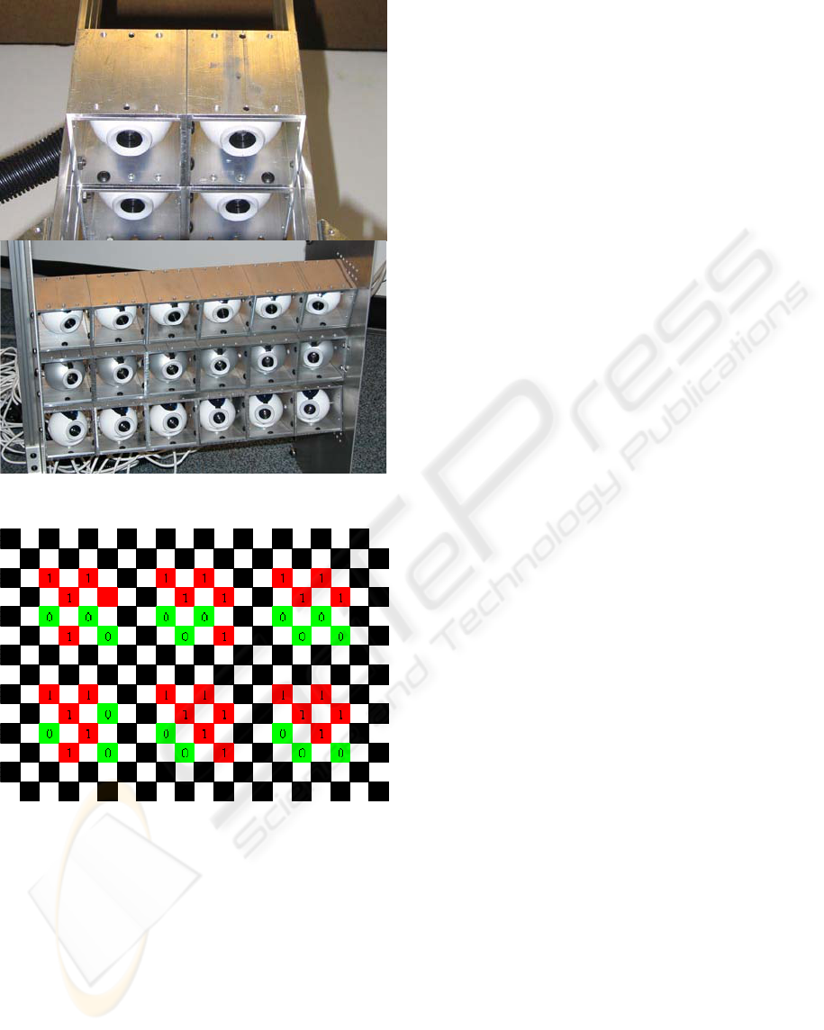
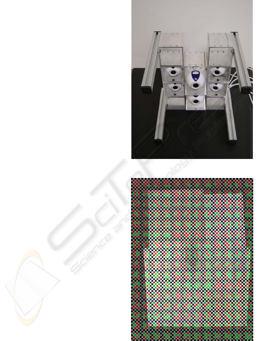
Figure 1: Different configurations of the Reconfigurable
Camera Array for Machine Vision Inspection (RAMVI).
Figure 2: A region from the CCG. Each colour word is a
unique binary number, ordered in a sequence in rows and
columns.
Further details and formulation on the calibration
approach developed can be found in (Abramovich,
2005) from a computation aspect. This paper focuses
on the issue of colour recognition, which is essential
for proper automatic calibration. The new approach
presented here incorporates a robust rule-based
colour recognition methodology in the calibration
process.
The paper proceeds as follows: Section 2
summarizes the colour-coded calibration process.
Next, in section 3, a rule-based approach for colour
recognition is presented along with reasons for using
this approach instead clustering. Section 4 presents
experimental results, demonstrating the robustness
of the rule-based approach. Section 5 provides
conclusions and explores possible extensions to the
system using error correction methods.
2 COLOUR CODED
CALIBRATION
The calibration method presented in this work relies
on a special Colour-coded Calibration Grid (CCG).
The method is able to reduce lens distortion, reduce
perspective effects, and stitch multiple images
together.
The purpose of a CCG is to establish a machine-
readable pattern that accurately, uniquely, and
reliably defines point positions and grid orientation
using colour information in a pre-specified pattern.
This is a necessary enabler for automating the
calibration of multiple cameras.
The CCG is composed of a sequence of colour
“words” that can be read as unique numbers in base
b , where b is the number of colours used other
than black and white. These calibration words are
constructed from patterns of colour-squares. In
figure 2 each colour-square represents a binary digit
in the word/binary number. Each word is separated
by rows and columns of black and white squares.
The actual CCG used in this work was
constructed by printing the calibration pattern on
paper. A total of 192 word combinations on the
CCG were printed so that 12 words were written
across and 16 words were written down.
A calibration method based on the CCG is
composed of the following main stages:
1. Automatic grid corner detection – In this
stage the grid lines are detected and intersected
to locate the grid corners. These corners will
later serve as feature points in calculations for
distortion and correspondence between images.
2. Calculation of image distortion parameters –
The lens distortion is estimated from the
arrangement of the detected corners, assuming
ideal conditions for other intrinsic parameters.
Corner positions are refined to account for the
lens distortion.
3. Grid cell colour recognition – grid cell colours
are recognized to determine the location and
orientation of the image on the CCG.
4. Calculating image transformation – This
stage uses the corner points and the location and
orientation of each image on the CCG. The
VISAPP 2006 - IMAGE FORMATION AND PROCESSING
132
calculated transformation allows combining the
images into a single higher resolution image.
Overlapping fields of view are combined to
retain the more accurate image during this stage.
Using the unique structure of the CCG the
calibration procedure above can determine the field
of view of each individual camera with respect to the
CCG. During this process it is important to correctly
recognize each colour. Colour recognition may be
hampered by poor lighting conditions, shadows, and
cameras with varying sensitivity. Moreover, since
the amount of information collected by multiple
cameras is large, the chance of error increases. For
this reason, a robust colour recognition technique is
essential. Hence, in the following section, methods
for robust colour recognition are discussed and
compared.
3 RULE-BASED COLOUR
RECOGNITION APPROACH
When reading the CCG it is essential that a RAMVI
system interpret the colours correctly. In prior work
(Abramovich, 2005) empirical data was used to
create a nearest neighbour “codebook” containing all
the combinations of RGB values that corresponded
to particular colours. This codebook was then used
to determine the colour of each colour-square during
the calibration process. The approach worked well
as long as the codebook was generated with data
based on similar lighting conditions and camera
sensitivities. However, since it may not be possible
to ensure the same lighting conditions and camera
sensitivities, it is beneficial to use a more robust
approach. One approach to colour recognition with
no a priori information could be to employ
clustering analysis.
3.1 Colour Recognition Using
Clustering
Figure 3 shows an example image where K-means
clustering (Corney) was applied to recognize grid
cell colours for a grid with five colours (black,
white, red, green, and blue). The plot below the
image shows the RGB components of each grid cell
colour along with the location of the centre of each
identified cluster. In this case, the initial estimates of
the cluster centres were randomly generated. The
results demonstrate the difficulty of correct
clustering. Some clusters were represented by more
than one centre , while others were combined.
Poor lighting conditions, as in Figure 4, can
further complicate colour recognition. In this case, a
four-colour CCG was used (i.e. black, white, red,
and green). For this case, even when intelligently
predetermined initial conditions were employed for
the k-means clustering, the results do not represent
the colours of the CCG well. For example, white
was represented twice, and green was not.
Figures 3 and 4 demonstrate how clustering is
sensitive to lighting conditions and initial conditions.
It is also sensitive to
k (the number of cluster
centres desired). Note if
k is chosen to be greater
than the number of colours in the image, then
additional classification is required.
Figure 3: Colour clustering using K-means with random
initial conditions. (Top) Example image with five colours.
(Bottom) Plot of grid cell RGB components and detected
cluster centres.
Since image characteristics can vary from camera
to camera, even powerful tools such as clustering
may not produce the desired results. Other clustering
methods (Corney) were also explored and similar
limitations were encountered. Regardless, after
clustering, one must assign the appropriate colour to
each identified cluster centre, which requires a rule.
Such rules may not be intuitive, i.e. green clusters
may not always have the highest component of
green. Hence, a rule-based approach was developed,
which eventually replaced the need for clustering.
ROBUST CALIBRATION OF A RECONFIGURABLE CAMERA ARRAY FOR MACHINE VISION INSPECTION
(RAMVI): Using Rule-Based Colour Recognition
133
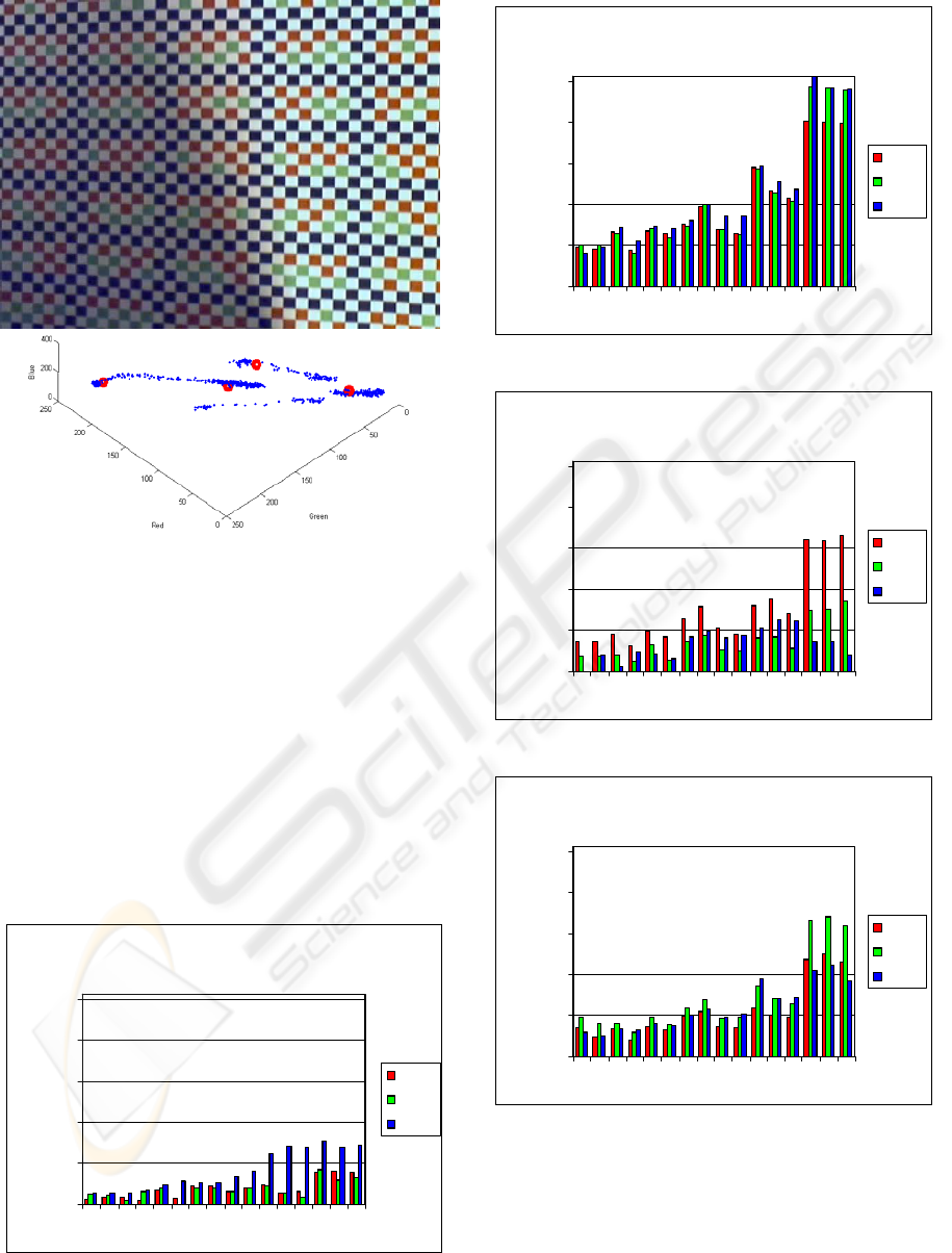
Figure 4: Colour Clustering using K-means with pre-
determined initial conditions. (Top) Example image with
four colours. (Bottom) Plot of grid cell RGB components
and detected cluster centres.
3.2 Rule-Based Approach
Rules for determining grid cell colours were
established upon examination of a variety of colour-
squares obtained from a variety of images from the
system cameras. To minimize the complexity in
colour recognition, the number of colours in the
CCG was restricted to four (i.e. black, white, red,
and green). Figures 5-8 show the data obtained from
the sample colour-squares.
Black Values
0
50
100
150
200
250
13579111315
rgb value
red
green
blue
Figure 5: RGB values of selected black colour-squares.
White Values
0
50
100
150
200
250
13579111315
rgb value
red
green
blue
Figure 6: RGB values of selected white colour-squares.
Red Values
0
50
100
150
200
250
13579111315
rgb value
red
green
blue
Figure 7: RGB values of selected red colour-squares.
Green Values
0
50
100
150
200
250
13579111315
rgb value
red
green
blue
Figure 8: RGB values of selected green colour-squares.
Based on this information, the following
observations were made:
1. White colour squares had the highest RGB
components, and little variation between the
green and red components. Also, half of all
colour-squares are white in the CCG.
VISAPP 2006 - IMAGE FORMATION AND PROCESSING
134
2. Black colour squares had the lowest RGB
components and little variation between the
green and red components. Also, the proportion
p
of black colour-squares can be calculated
from the CCG structure.
3. Red colour-squares had a higher red component
than green colour-squares.
4. Green colour-squares had a higher green
component than red colour-squares.
5. Words in the CCG represent binary numbers
which are written in a predetermined sequence.
Based on these observations, the following
procedure for colour recognition was developed:
1. Using previously identified grid corners,
average the colour components of the pixels in
the interior of each grid colour square. This is
denoted as
[]
nmibgr
iii
Κ1,,, = .for a grid
image with
nm squares.
2. Calculate the range between the green and red
colour components.
() ()
iiiii
grgrd ,min,max −=
3. Calculate the average intensity for each square
and store it.
()
3/
iiii
bgra +
+
=
4. Calculate a weight factor combining the
previous two values
()
iii
daw −+= 1 .
5. Identify the half , meaning
2/nm , colour
squares with the highest value of
i
w label them
white, and remove them from the analysis.
6. Identify a portion, meaning
nmp
, of colour
squares with the lowest value of
i
d label them
black, and remove them from the analysis.
7. Label the remaining squares green if
ii
rg > ,
otherwise, label them red.
8. “Read” all words in the image
9. Determine the word which best agrees with the
remaining words according to the numerical
sequence of the CCG. Select this word to define
the position of the image on the CCG.
Section 4 offers experimental results that
demonstrate the effectiveness of this approach.
4 EXPERIMENTAL RESULTS
This section presents results in two levels. First the
rule-based colour recognition method is verified
experimentally on individual images in section 4.1.
Then section 4.2 presents results for full calibration
and image construction of the RAMVI system.
4.1 Rule-Based Colour Recognition
Results
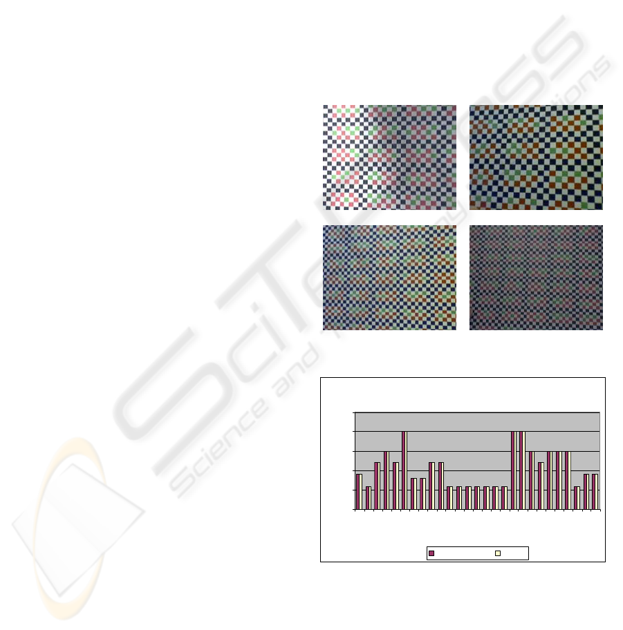
In order to verify the performance of the rule-based
colour recognition approach, the method was tested
on 27 CCG images, where the grid corners had
already been correctly established. These images
demonstrate the variety of lighting conditions and
square sizes that are encountered during the use of
the system. Figure 9 shows a representative subset of
these images, including an extreme change of
intensity of illumination within the image.
Figure 9: Four sample images out of 27 used to test the
rule-based colour recognition approach.
Words Correctly Identified
0
5
10
15
20
25
1 3 5 7 9 111315171921232527
Image Number
Number of Words
Words Identified Words
Figure 10: Number of words corrected detected in each
test image compared to the number of possible words.
Figure 10 is a bar chart showing the number of
words that were correctly detected using the rule-
based approach. The yellow bars indicate the
number of words in the image, which depends on the
image magnification. The red bars indicate the
actual number of words detected correctly. In all 27
ROBUST CALIBRATION OF A RECONFIGURABLE CAMERA ARRAY FOR MACHINE VISION INSPECTION
(RAMVI): Using Rule-Based Colour Recognition
135
images, every word was detected correctly,
demonstrating the robustness of the method.
4.2 Full System Calibration and
Image Construction
The rule-based colour recognition procedure was
integrated into the RAMVI calibration method using
a six-camera configuration as shown in figure 11.
First the system was calibrated using the CCG. As a
result of the RAMVI system calibration, the relative
position of each camera was established and lens
distortions and perspective effects were removed.
This enabled the construction of the images seen by
all cameras into a single image. Figure 12 shows the
constructed CCG image overlaid on to the original
computer-generated CCG.
Following the system calibration, the CCG was
replaced by a part and images were acquired by the
RAMVI system. Using the transformation matrices
obtained through the calibration method, a single
image of the part was constructed. This is displayed
in figure 13. In practice, the calibration procedure
would be performed only once. Thereafter images of
parts can be repeatedly acquired and constructed
without additional calibration as long the part
surface remains on the calibration plane. The
cameras are not restricted to be on the same plane,
nor be pointed in the same direction. Overlap
between images is optional as images are not
mutually registered, but numerically matched to an
ideal master.
Figure 11: The six-camera RAMVI configuration used in
this experiment.
Figure 12: Image of the constructed CCG overlaid on to
the original computer-generated CCG.
VISAPP 2006 - IMAGE FORMATION AND PROCESSING
136
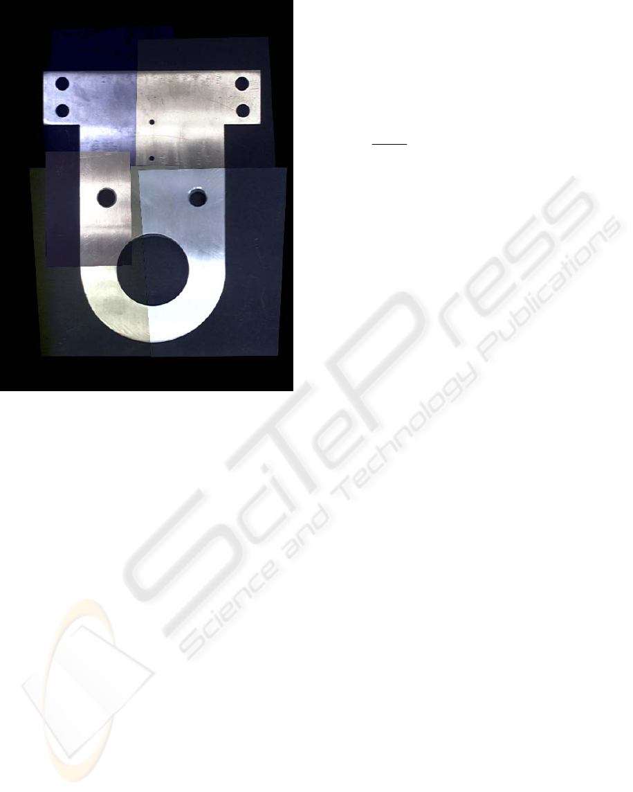
Figure 13: Image of the constructed part composed of the
images obtained by the 6 cameras.
5 CONCLUSIONS, DISCUSSIONS
AND POSSIBLE EXTENSIONS
The results demonstrate robust calibration of a
camera array using a rule-based colour recognition
approach. The approach performed well in a variety
of lighting conditions and in a practical experiment.
To allow the system to work with a larger variety
of cameras and in varying lighting conditions during
calibration, rather than developing rules of greater
complexity, it might be beneficial to consider
implementing error correction (Anderson, 1974) in
the CCG. For example, Reed-Solomon error
correction (Communications toolbox) is a common
method used for binary messages. Since the words in
the CCG are also binary, the Reed-Solomon
approach may be applicable. In this context, the
following notation is defined:
s = number of bits (colour squares) in each
symbol (a symbol is one row in the word).
n
= length (number of symbols) of the
codeword
h = length (number of symbols) of the portion
of the codeword with the actual data
hnp −= = length (number of symbols) of
the portion of the codeword with parity symbols
t = number of symbols that can be corrected
Using the Reed-Solomon approach, the
maximum code word length is:
12n
s
max
−= (1)
.
And the number of symbols that can be corrected
using Reed-Solomon is:
2
hn
t
−
=
(2)
Each code word contains
h symbols that contain
the message and
p
parity symbols. Parity provides
redundant information to enable de-coding of the
word if a portion of it is read incorrectly. Error
correction is improved with more parity symbols.
Hence a larger code word length is desirable for
error correction.
However, Reed-Solomon has some limitations in
this context. First of all, Reed-Solomon can only
correct portions of words. Unfortunately, poor
lighting conditions such as shadows may obscure
whole words, making Reed-Solomon ineffective.
Secondly, Reed-Solomon also increases the sizes of
words significantly. Yet it is important that the word
size remain small so that at least one full word is
shown in each image of the CCG. Hence
t , the
number of symbols that can be corrected, is
significantly limited.
The alternative approach that was chosen is to
take advantage of the pattern of words that are
written on the CCG. Since they are written in a
sequential numerical order, the sequence can be
exploited to eliminate errors. After reading all of the
words in an image, one can verify that all words are
in a sequential order with respect to each other. If
the sequence is broken unpredictably, then an error
has occurred. Likewise, if most words are in
agreement with the sequence, the remaining words
can be corrected according to the majority.
This approach has two advantages over Reed-
Solomon. First, it works well with small word sizes
and a large number of words per image. This is in
agreement with the requirement to keep word size to
a minimum to ensure that each image contains at
least one word.
Secondly, this approach uses much more
redundancy. In most cases, several words will be
present on each image. Since only one word must be
read correctly for calibration, when several words
are present, this approach is very effective.
Therefore, the advantages of error correction are
already achieved by this approach through
exploitation of the word sequence. This is because
the word used to define the image position with
respect to the CCG is chosen on the basis of its
agreement with the remaining words according to
ROBUST CALIBRATION OF A RECONFIGURABLE CAMERA ARRAY FOR MACHINE VISION INSPECTION
(RAMVI): Using Rule-Based Colour Recognition
137

the CCG sequence. No correction is applied, but the
end result of determining the correct positioning is
still achieved. Hence the current approach is quite
robust, and it is not likely that much improvement
would be obtained by adding Reed-Solomon error
correction.
In the future, if colour correction is desired, then
word sequencing could be exploited further as a
means to go back and correct the recognition of each
individual colour square so that it is in complete
agreement with the determined word sequence. This
would enable, for example, improvement in image
brightness and colour rendering.
ACKNOWLEDGEMENTS
The authors gratefully acknowledge the financial
support of the Engineering Research Center for
Reconfigurable Manufacturing Systems (NSF Grant
EEC-9529125) at the University of Michigan and
the valuable input from the center’s industrial
sponsors. Special thanks to Nelson Woo, Brent Carr,
Kyung Han, David Wintermute, and Steve Erskine
for their aid in system construction and software
programming.
The authors thank Jean-Yves Bouguet for
publishing the Camera Calibration Toolbox for
Matlab on the Internet.
REFERENCES
Wilburn, B., Smulski, M., Lee, H.H., Horowitz, M., 2002,.
The Light Field Video Camera. Proc. of Media
Processors 2002, SPIE Electronic Imaging.
Wilburn, B., Joshi, N., Vaish, V., Levoy, M., Horowitz,
M., 2004. High-Speed Videography Using a Dense
Camera Array. Proceedings of the 2004 IEEE
Computer Society Conference on CVPR 2004, Vol. 2,
pp. 294 – 301.
Vaish, V., Wilburn, B., Joshi, N., Levoy, M., 2004. Using
Plane + Parallax for Calibrating Dense Camera
Arrays. Proceedings of the 2004 IEEE Computer
Society Conference on CVPR 2004, vol. 1, pp. 2 – 9.
Yang, J.C., Everett, M., Buehler, C., McMillan, L., 2002.
A Real-Time Distributed Light Field Camera,
Thirteenth Eurographics Workshop on Rendering.
Zhang, C., Chen, T., 2004. A Self-Reconfigurable Camera
Array, Eurographics Symposium on Rendering.
Naemura T., Tago J., Harashima H., 2002. Real-Time
Video-Based Modeling and Rendering of 3D Scenes.
IEEE Computer Graphics and Applications, Vol. 22 ,
Issue 2, pp. 66 – 73.
Koren, Y., Ulsoy, A.G., 2002, Vision, Principles and
Impact of Reconfigurable Manufacturing Systems,
Powertrain International pp.14-21.
Bouguet, J.Y., Camera Calibration Toolbox for Matlab,
http://www.vision.caltech.edu/bouguetj/calib_doc/
Tsai, R.Y., 1987. A versatile camera calibration technique
for high accuracy 3d machine vision metrology using
off-the-shelf tv cameras and lenses. IEEE Journal of
Robotics and Automation, Vol. RA-3, No. 4, pp. 323-
344.
Heikkilä, J., Silvén, O., 1997. A Four-step Camera
Calibration Procedure with Implicit Image Correction.
Proceedings of the 1997 IEEE Computer Society
Conference on CVPR'97, San Juan, Puerto Rico, pp.
1106-1112.
Brown M., Lowe D.G., 2003. Recognizing Panoramas.
Ninth IEEE International Conference on Computer
Vision (ICCV 2003), Nice, France.
Shum H.-Y., Szeliski R., 1998. Construction and
refinement of panoramic mosaics with global and local
alignment. Sixth International Conference on
Computer Vision (ICCV'98), pages 953-958, Bombay.
Abramovich G., Barhak J., Spicer P., 2005. Camera
Arrays for Machine Vision Inspection. The 2005 CIRP
3rd International Conference on Reconfigurable
Manufacturing, May 10-12, Ann Arbor, Michigan.
Anderson I., 1974. A First Course in Combinatorial
Mathematics, Oxford University Press, pp. 92-96.
Corney D., Clustering with Matlab,
http://www.cs.ucl.ac.uk/staff/d.corney/ClusteringMatl
ab.html
Communications Toolbox, Creating and Decoding Reed-
Solomon Codes., www.mathworks.com
VISAPP 2006 - IMAGE FORMATION AND PROCESSING
138
