
HUMAN BODY TRACKING FOR PHYSIOTHERAPY VIRTUAL
TRAINING
Sara Shafaei, Mohammad Rahmati
Computer Engineering Dep.,Amirkabir University of Technology (Tehran Polytechnic),
Hafez Ave, No 424, P.O.BOX 15875-4413 Tehran, Iran
Keywords: Human motion tracking, virtual training, physiotherapy, machine vision
Abstract: In this paper, we introduced a system in which it can be used for patients who are prescribed to undergo a
physiotherapy treatment. In this personal virtual training system we employ several markers, attached to the
various points of the human body. The system provides a physiotherapy session to the user, once the session
is repeated by the user, the video image sequence captured by the system is analyzed and results are
displayed to the user for further instructions. Our design consists of 3 general stages: detection, tracking,
and verification stages. In the detection stage, our aim is to process the first frame of the image sequence for
detecting the locations of the markers. In order to reduce the computational complexity of the first stage, the
detection was performed in the lower scale of a Gaussian pyramid space representation. The second stage of
our system performs tracking of detected markers of the first stage. A prediction algorithm is applied in this
stage in order to limit the search along the predicted directions during the search for the markers in
subsequent frames. For verification stage, the trajectory of the markers will be compared with the
information in the model. Trajectory matching is performed by computing the difference between their
smoothed zero-crossing potentials of the captured trajectory and the model.
1 INTRODUCTION
Human motion analysis by computer has become an
important research issue in different areas of
medicine and human science. In clinical gait
analysis, for example, the temporal information
about the position and orientation of the patient’s
joints may be useful in determining abnormalities
(Yeasin ,2000). In orthopedics, the range of motion
information helps in the evaluation of the prosthetic
join replacement and physical therapy of joint
disease (Richards,1999). Postural analysis during
human motion can be studied from the
representation of the column through the position of
the markers fixed to the spinal process
(Crosbie,1997). Athletic performance can also be
improved by breaking down the movement into
elementary components and by identifying suitable
reference models arising from the observation of the
outstanding athletes (Pedotti,1983).
For these reasons, there is a great interest in
developing measurement techniques that allow a
more accurate and automatic analysis of the human
movement. In particular, systems based on markers
and cameras, have been extensively used to record
kinematics of the human motion (Richards,1999).
Markers can be defined as special objects that are
attached or fixed to the human body, helping to track
the movement of important points.
In this paper, we present the design and
implementation of a virtual personal physiotherapy
trainer prototype using markers to improve the
results. This system establishes a personalized
physiotherapy session for the user and displays the
resulting instruction on a monitor. The user
periodically receives visual feedback from the
virtual instructor on how he/she is currently doing.
To accomplish this, we use a video camera in the
room and incorporate various real-time computer
vision techniques. Following presentation of a
movement by an instructor, the patient repeats the
movement accordingly. By capturing the video
sequence of the trainee the task of the system is to
recognize the physiotherapy movement of the user
using the output of the vision system. In order to
improve the performance of our system user needs
to wear 12 markers. A cartoonish-like characters
maybe used as the virtual instructors, but in this
449
Shafaei S. and Rahmati M. (2006).
HUMAN BODY TRACKING FOR PHYSIOTHERAPY VIRTUAL TRAINING.
In Proceedings of the First International Conference on Computer Vision Theory and Applications, pages 449-454
DOI: 10.5220/0001364704490454
Copyright
c
SciTePress

system we chose to use stored movie clips for
simplicity. While we use only one instructor it
might be more instructors involved. We currently
have twelve physiotherapy moves used in our
system.
Currently, a set of movie clips, showing a full
view of the instructor, is used. In each clip the
instructor performs a single cycle of the move then
visual feedback of the instructor is displayed. In our
proposed system if the algorithm recognizes that the
user is performing the physiotherapy move correctly,
it notifies the user that he performs complete
movement correctly and if the user movement is
wrong, system notifies the user that his movement is
wrong and along with the information that which
part of the body had wrong movement.
Our design is divided into the following three
procedures: 1. Detection of the markers in the first
frame. 2. Tracking markers in the rest of the frames
and finding the trajectories 3. Matching motion
trajectories with stored model.
The paper is organized as follows. In section 2
we introduce, without going into the details, the
pervious systems related to human movement
analysis. In Section 3 we described the method that
was used for detection of markers in the first frame,
and in Section 4 we explain how to track markers in
a video sequence and this is divided into two
procedures: matching and prediction. The matching
is used to find correspondence between the extracted
objects of two consecutive frames. The prediction
stage is an important stage in order to limit the
search region, thus reducing the execution time. In
Section 5 the verification of the trajectories,
recorded from markers movements, will be
discussed and they are compared with the
information for the models. Comparison between a
trajectory and the model is performed by computing
the difference between their smoothed zero-crossing
potentials. Our experimental results are in Section 6
and conclusion is in Section 7.
2 PREVIOUS SYSTEM
A system called W4 ( Haritaoglu,1998) is a real time
visual surveillance system for detecting and tracking
people and monitoring their activities in an outdoor
environment. It operates on monocular grayscale
video imagery, or on video imagery from an infrared
camera.
Other system called Pfinder (Wren ,1997) is a
real-time system for tracking a person which it uses
a multi-class statistical model of color and shape to
segment a person from a background scene. It finds
and tracks people’s head and hands under a wide
range of viewing condition.
System introduced by Kidrooms (Bobick,1996)
is a tracking system based on “closed-world
regions”. These are regions of space and time in
which the specific context of what is in the regions
is assumed to be known. These regions are tracked
in real-time domains where object motions are not
smooth or rigid, and where multiple objects are
interacting.
3 DETECTION
As mentioned earlier, there are 12 markers; as
shown in Figure 2; these are used to locate important
human body points. Detection of markers in the first
frame is an important step in our proposed system.
We used a Gaussian Pyramid representation in order
to decrease computational processing time. Each
level of a Gaussian pyramid is a lower resolution
with respect to the previous one. In each level we
simply performed two operations: 1) low-pass filter
of the image, and 2) discarding the odd numbered
rows and columns from the filtered image. These
operations performed for both of input image and
template image. Low-pass filtering of input image is
accomplished by taking a weighted average of a 5x5
region surrounding at each image pixel. To increase
computation efficiency, a separable equivalent
weighting function was used to perform the 5x5
weighted averages. At first, convolving an image
with a 1x5 weighting function, the 'horizontal'
weighted average of the image is obtained. Next,
convolving the horizontally averaged result with the
transpose of the 1x5 vector (i.e. a '5x1') weighting
function results the 'vertical' weighted averaging. A
Gaussian-like weighting function with values of [.05
.25 .5 .25 .05] was used as the impulse response of
our filter. Due to our input image frame size, we
used the two-level pyramid in our system. As an
example, a frame of video sequence in the original
size and its lower resolution is shown in the Figure
2.
Once the resolution of an image and the template is
decreased, using Gaussian pyramid at one level, then
a template representing a marker must be searched
in the lower level. When located, then we find the
probable locations of the markers within the 2x2
region surrounding the places found in the
corresponding locations of the original image. The
cross-correlation function is used for detection,
given by the following relationship.
VISAPP 2006 - MOTION, TRACKING AND STEREO VISION
450
22
)),(()),(),((
)),())(,(),((
∑∑∑∑
∑∑
−=−=−=−=
−=−=
−−++
−−++
=
M
Mm
N
Nn
M
Mm
N
Nn
M
Mm
N
Nn
ij
hnmhjifnjmif
hnmhjifnjmif
C
(1)
where
ij
C
is the cross correlation value at (i,j)th
location between function f(,), the color image for
original image and gray image for lower level image
in the searched region, and h(,), the model of the
marker with (2M+1)× (2N+1) pixels. The values
f
and
h
are the mean of f and h, respectively. In
Figure 3, detection of markers in one of our
experiments at low and high resolutions is shown.
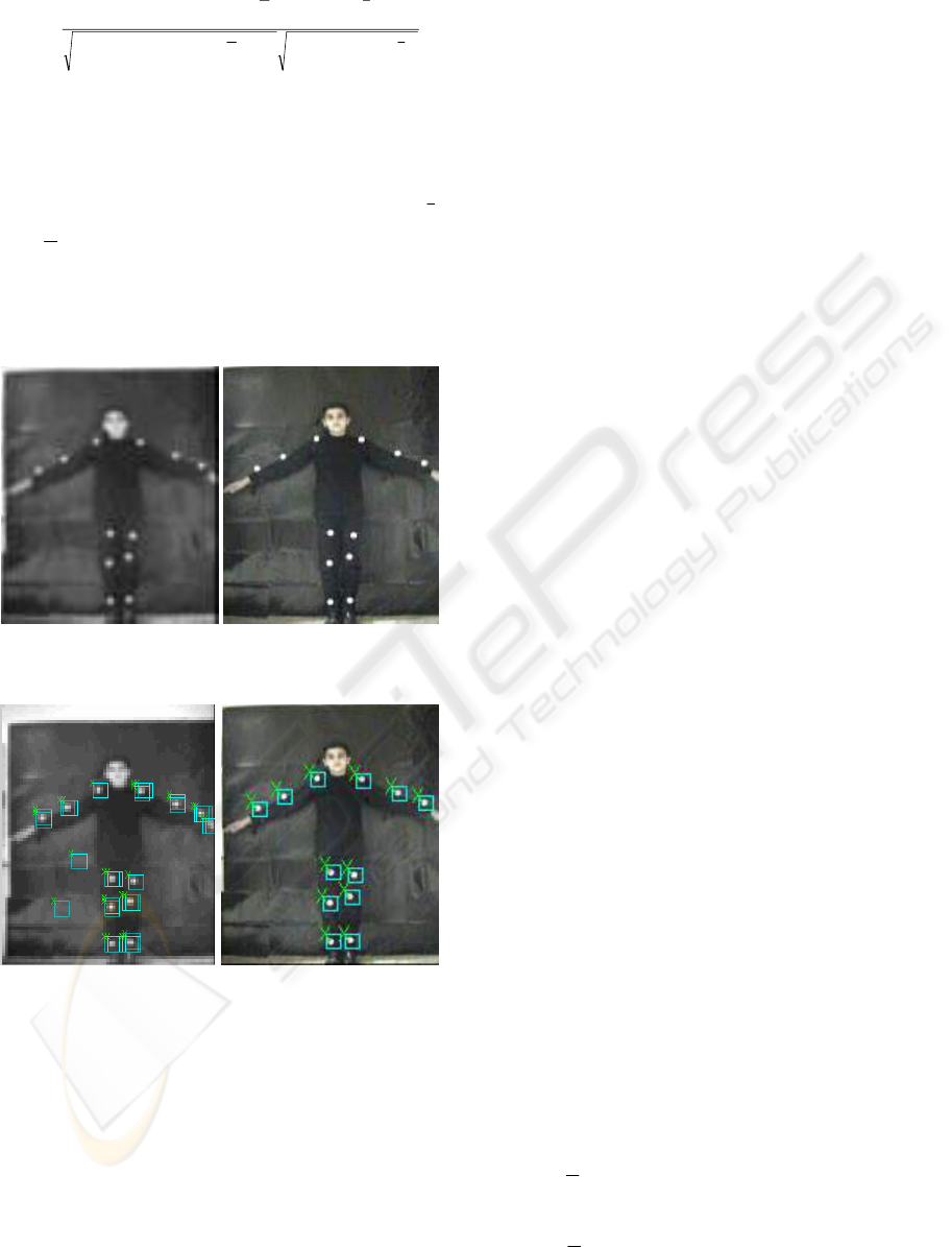
(a) (b)
Figure 2: (a) lower resolution (b) Original image.
(a) (b)
Figure 3: (a) marker found in lower resolution (b)
Location of marker found at original image shown with
squares.
4 TRACKING
Tracking the motion of human's parts, in a sequence
of images, is an important step in automatic analysis
of the human movement. This is a challenging
problem due to non-rigidity of the human body, the
influence of the environment, and other constraints.
The automatic tracking can be used in a variety of
applications, such as clinical gait analysis
improvement of the human performance in sports,
ergonomics, and so on. This involve in two parts,
matching and prediction.
4.1 Matching
Matching is referred to as steps necessary to find the
correspondence of markers between 2 consecutive
frames. The matching between a marker model and
its corresponding within an image is based on the
gray-scale values of the pixels and it is evaluated by
the Mean Absolute Difference (MAD) function
between the marker model and a portion of the
image within the search region. The template
matching is accomplished by locating the points
where MAD between the image and the model is
minimized. In this way, the computation complexity
is highly reduced. The MAD at (i, j)th location is
defined as
|)),(),((| nmhnjmifD
M
Mm
N
Nn
ij
∑∑
−=−=
−++=
,(2)
Where f is input image within the search area and
h is the pixel value of the model representing the
marker of size (2M+1)× (2N+1) pixels. The
location with minimum value is location of marker.
4.2 Prediction
The matching function is applied to the significant
regions extracted from the segmentation algorithm
in the prediction step. This local aspect reduces the
processing time of the matching step. Of course,
regions with high correlations are selected
corresponding to the expected position of the
markers.
In order to reduce the search region, it is
necessary to define a mechanism to predict the
possible positions of the markers at the successive
frames. For this purpose, we can use a simple
extrapolation function. This can be done by a rough
prediction, according to the following extrapolation
function:
)57(
3
1
21 −−
+−=
kkkc
xxxx
)57(
3
1
21 −−
+−=
kkkc
yyyy
, (3)
HUMAN BODY TRACKING FOR PHYSIOTHERAPY VIRTUAL TRAINING
451
where
k
x and
k
y are the spatial location of the
current markers point for the kth frame, and
c
x ,
c
y
represent the center of the searching region for the
(k+1)th frame, after finding
c
x ,
c
y We searched
region around
c
x ,
c
y with radius 7 pixel for finding
marker. In fact region size for markers searching is
15*15 pixels. We determined this region size from
several experiments.
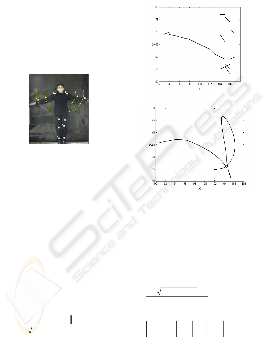
Figure 4 : Trajectory of motion after tracking.
5 VERIFICATION OF MOTION
5.1 Smoothing Trajectory
A trajectory is a spatio-temporal curve defined as:
(x[1],y[1], 1), (x[2], y[2], 2),…, (x[n], y[n], n) where
x[n],y[n] are coordinate value of a marker in frame
n. There are essentially two 1-D functions involved:
x[n] and y[n] in the above definition of a trajectory.
A trajectory for a specific action performed in one of
our demonstration is shown in the Figure 4 and its
temporal function is shown in Figure 5b. This
trajectory contains some noise due to errors during
tracking. In order to deal with this noise, we use a
Gaussian kernel as defined below, and apply it to the
noisy signal to smooth x[n] and y[n] coordinates of
the trajectory. We convolve trajectory with
Gaussian kernel described by equation given below.
For our experiments s =2 was selected. Result of
smoothing is shown in the Figure 5a.
)
2
exp(
)2(
1
)(
2
2
s
x
s
xG
s
−=
π
(4)
(a)
(b)
Figure 5 : (a) noisy trajectory of marker (b) Smoothed
trajectory of marker.
5.2 Spatio-temporal Curvature
Parameterization
We use spatio-temporal curvature (Cedras, 1995) to
represent an action. In this case, a 1D version of a
quadratic surface fitting procedure is used. The
spatio-temporal curvature, represented by k, is
computed as follows:
2/3222
222
))()()(( zyx
CBA
k
′
+
′
+
′
++
=
, (5)
Where
yx
yx
C
xt
xt
B
ty
ty
A
′′′′
′′
=
′′′′
′
′
=
′′′′
′
′
= ,,
where the notation |·| represents the determinant
of a matrix. The first and second derivative of a
function x(t) is denoted by
)1()()(
−
−=
′
txtxtx
,
VISAPP 2006 - MOTION, TRACKING AND STEREO VISION
452
)1()()( −
′
−
′
=
′′
txtxtx
, respectively. Since the time
interval is constant, so
1
=
′
t
, and t" = 0.
The spatio-temporal curvature has the advantage
over other trajectory parameterizations since it
captures both the speed and direction changes in one
quantity. Figure 6 depicts the spatio-temporal
curvature for a trajectory as captured from Figure 5.
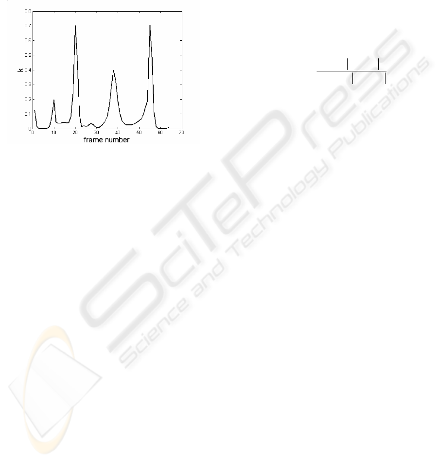
Figure 6: Spatio-temporal curvature for trajectory Figure
5.
5.3 Matching Trajectory
There are twelve trajectories related to the twelve
markers which will be compared with the stored
information of the model. A match score for each
marker is produced which indicates how closely the
two trajectories matched.
Matching between two trajectories is evaluated
by computing the difference between their smoothed
zero-crossing potentials, and employing the idea of (
Rangarajan,1993) for matching the scale-space
representation. The first step in this algorithm is to
decompose the trajectory into 1D signal, the spatio-
temporal curvature that was explained in the
pervious section. The scale-space is computed by
repeatedly convolving the input spatio-temporal
curvature signal with second derivative of Gaussian
mask with various σ values. The output is then
checked for zero-crossings, the indicative of
discontinuities. The location and potential (the
absolute difference between the values where the
zero-crossing occurs) of each zero-crossing is stored
in a set of arrays, one for each σ value. The set of
arrays is organized into a two dimensional table,
with the location (frame number) as the x axis and σ
as the y axis. It is well known that the zero-
crossings of a distorted signal are dislocalized and as
a result, the zero-crossing potentials from a distorted
signal are not the same as those from an undistorted
signal. However, a smoothed zero-crossing
potential is less sensitive to noise, so the zero-
crossing from that table are diffused by convolving
with a two dimensional Gaussian of standard
deviation equal to 1 (see figure 7). In the next step,
this array is multiplied by a scaling factor and the
results are stored as an array. The matching itself is
done by element by element subtraction operations
between the diffused input and the model in the
scale-spaces representation. The absolute values
from the subtraction are stored. In the final step, the
match score is computed using the following
equation:
∑
∑
∑
∑
−=
),(*2
),(
1
σα
σε
n
n
scorematch
k
k
(6)
where
k
ε
is the array containing the element by
element subtraction of input and model, for spatio-
temporal curvature and
k
α
represent spatio-
temporal curvature of the model. If this score is
lower than the preset threshold, we used a value of
0.7 for the threshold, then the user’s motion is
wrong, otherwise it is right. The user is notified due
to the wrong joint movements.
6 EXPERIMENTS
Images of our video sequences are 144x176 pixels in
size. We have considered twelve different
physiotherapy actions performed by a user, and we
have recorded a large number of video sequences. In
Figure 8 we have shown a few frames from only 2
different moves. We have considered cases where
the markers may come very close to each other; even
in some cases we had overlaps between the markers.
We also tested the system under different speed of
body movements. Results of detection and tracking
in all actions were performed correctly and there
were no errors in the verification of all twelve
movements. Figure 8 shows sequences of two
actions. Our overall evaluation will be completed
once the system is tested with complex movements.
7 CONCLUSIONS
In this work, we introduced a system for a virtual
personal physiotherapy trainer. One of the main
advantages of this system is its comfort and
possibility of using it in personal environment for
training physiotherapy movement where the
HUMAN BODY TRACKING FOR PHYSIOTHERAPY VIRTUAL TRAINING
453
therapists is not available or patient may be at
remote area in which the expert is not readily
accessible. The important feature of the system is its
precision, and furthermore, if the user’s movement is
wrong, the system would notify the user of the error
and advise the patient, that which part of the
movement was wrong.
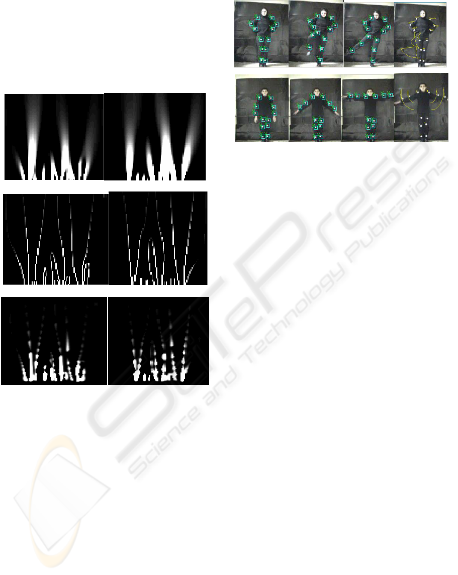
(a)
(b)
(c)
Figure 7: (a) Scale-space of spatio-temporal of trajectory a
sample and reference motion (b) Zero-crossing potential
of the spatio-temporal curvature scale-space of trajectory a
sample and reference motion (c) The diffused zero-
crossing potential of the spatio-temporal curvature scale-
space of trajectory a sample and reference motion.
(a) (b) (c) (d)
Figure 8 : video sequences of four actions .There are 60
frames in each sequence . (a) frame 1 (b) frame 10 (c)
frame 40 (d) trajectory of markers.
REFERENCES
Bobick A. and Davis J. and Intille S. and Baird F. and
Cambell L. and Irinov Y. and Pinhanez C.and Wilson
A.,1996. KidsRoom: Action recognition in an
intractive story environment. M.I.T. TR , No.398.
Cedras C. and Shah M. , 1995. Motion-based
recognition: a survey, Image Vision Comput,
Vol.13, No.2 , pp.129–155.
Crosbie J. and Vachalathiti R.and Smith R., 1997. Pattern
of spinal motion during walking. Gait and Posture ,
Vol. 5, pp 6-12.
Haritaoglu I. and Harwood D. and Davis L. S.,1998. W 4 :
Who? When? Where? What? - A real time system for
detecting and tracking people. International
Conference on Automatic Face and Gesture
Recognition,Nara, Japan, pp 877-892 .
Pedotti A. and Farigo C. and Rodano R., 1983.
Optimization of motor coordination in sport an
analytical approach. Biomechanics and Performance
in Sports, Baumann,Schnordorf ,pp 145-/160.
Rangarajan K. and Allen W. and Shah M. , 1993.
Matching motion trajectories using scale-space.
Pattern Recognition, Vol. 26, No. 4, pp 595-610.
Richards J.G., 1999. The measurement of human motion:
a comparison of commercially available systems,
Human Movement Science, New York ,USA, pp 589-
/602.
Wren C.R. and Azarbayejani A. and Darrell T. and
Pentland A.P., 1997. Pfinder:real-time tracking of the
human body, IEEE Transactions on Pattern Analysis
and Machine Intelligence,Vol. 19, No. 7, pp 780-785.
Yeasin M. and Chaudhuri S., 2000. Development of an
automated images processing system for kinematic
analysis of human gait,Real-Time Imaging , Vol. 6, pp
55-67.
VISAPP 2006 - MOTION, TRACKING AND STEREO VISION
454
