
REAL-TIME RENDERING OF HIGH QUALITY GLARE IMAGES
USING VERTEX TEXTURE FETCH ON GPU
Hidetoshi Ando, Nobutaka Torigoe
Department of Computer and Media, Graduate School of University of Yamanashi,
Takeda 4-3-11, Kofu, Yamanashi, JAPAN
Koji Toriyama, Koichi Ichimiya
Department of Mechanical Engineering, Graduate School of University of Yamanashi,
Takeda 4-3-11, Kofu, Yamanashi, JAPAN
Keywords: Real-Time Rendering, GPU, HDR Glare Image, Vertex Texture Fetch.
Abstract: Using recent graphics hardware called GPU (Graphics Processing Unit), we can render high quality
photorealistic images in real-time today. When rendering the scene, it is important to take into account how
human eyes percept the whole scene. Glare is a phenomenon whereby bright light source cause spreading
of light, and this effect is widely used in computer graphics to enhance reality of brightness of the scene.
Real-time rendering of glare images is very important for recent computer games and virtual reality
environment. Current technology for high quality glare rendering is too slow to be used for interactive
applications, and fast rendering technology is limited to generate only blurry glare images. In this paper we
introduce new technique for rendering high quality glare images in real-time using the latest technology
called vertex texture fetch. The basic idea is to put what we call degenerate polygons on the screen as
sensors to detect bright pixels and expand those polygons to form glare polygons where glare images are put.
Combined with some performance enhancement techniques, our method can render very high quality glare
images as fast as 60fps using modern GPUs.
1 INTRODUCTION
Computer graphics technologies are evolving very
rapidly and images rendered using techniques like
photon mapping or path tracing look much more
photorealistic than using legacy ray tracing. In
rendering of photorealistic scenes, it is not enough to
create images based on physically based methods,
but it is also important to take into consideration
how the scene is perceived by human eyes. The
most notable characteristics of human eyes are the
glare effect when we see dazzling bright lights in the
scene.
Glare is a phenomenon whereby bright light
source causes spreading of light. It is perceived as
blurry circle or a set of radial streaks around the
light source. As current computer displays are
physically limited by the maximum brightness,
rendering of bright scenes needs extra work for
human to perceive the scene really bright. Recently
glare image generation is considered very common
and effective technique to enhance visual reality of
brightness in computer-generated images.
It is well know that glare is caused by scattering
and diffraction of lights at obstacles close to or
inside our eyes. Many research works have been
done on generation of glare images based on
physical models of our eyes. Those high quality
glare images are widely used in recent CG movies
which were rendered off-line.
Real-time rendering of glare images are also
becoming very important to enhance visual reality of
recent computer games and virtual reality
applications. As recent GPUs support 16bit/32bit
texture format, real-time rendering of HDR (High
Dynamic Range) scenes became possible and
combination of HDR rendering with glare effect will
be crucial to next generation game consoles with
latest GPUs. However current techniques for real-
time rendering of HDR scene with glare images are
19
Ando H., Torigoe N., Toriyama K. and Ichimiya K. (2006).
REAL-TIME RENDERING OF HIGH QUALITY GLARE IMAGES USING VERTEX TEXTURE FETCH ON GPU.
In Proceedings of the First International Conference on Computer Graphics Theory and Applications, pages 19-25
DOI: 10.5220/0001354800190025
Copyright
c
SciTePress

quite limited either by image qualities or rendering
speeds. This means practically fast rendering
techniques are limited by image qualities and
rendering techniques for high quality images have
poor performance for real-time applications like
computer games. In this paper, we describe our new
techniques for high speed, real-time rendering of
high quality glare images using the latest
technologies on GPU and we hope to set the new
level of standard for next generation computer
games and interactive virtual environments.
2 RELATED WORKS
In this section we briefly overview some of the
important results from previous works on generation
of glare images and rendering techniques.
2.1 Generation of Glare Images
Many research works have been done on generating
glare images based on our visual experiences or
physical models of our eyes. Spencer et al.
developed a method based on physical structure of
human eyes to create glare images with sharp radial
streaks (Spencer et al., 1995) (see Figure 1(a)).
They took into consideration refraction and
scattering of light at various places in our eyes and
produced high quality glare images based on
physical and perceptual model. By placing those
glare images on bright light sources in the original
scene, they confirmed the human viewers perceived
the feeling of brightness although the computer
display was not bright enough.
Kakimoto et al. created glare images based on
wave optics (Kakimoto et al., 2005) (see Figure
1(b)). They developed a method to simulate
diffraction of light at human eyelash and pupil to
generate physically based glare images. By
changing the shapes of eyelash and pupil, various
kinds of glare images were generated automatically.
Glare images can be computed and generated off-
line and can be used later for real-time rendering
using graphics hardware.
2.2 Real-time Rendering of Scenes
with Glare Images
Recent advances in GPUs made it possible to render
HDR scenes with glare images in real-time.
Mitchell et al. used pixel shaders of ATI GPUs to
extract and blur bright pixels in the original HDR
scene to produce blurry glare images (Mitchell,
2002).
They developed an efficient implementation of 2D
Gaussian blur kernel to be performed on GPUs.
Using multiple pass rendering on GPUs to create
glare images and synthesize them with the original
scene, they could render the whole scene in real-time.
Kawase et al. developed efficient and practical
techniques for generating blurry glare images to be
used for computer games (Kawase and Nagatani,
2002). Their approach is similar to (Mitchell, 2002)
in that they implemented multiple pass blur filters
using pixel shaders on GPUs, but they also
developed blur filters for cross glares and pseudo
lens flares which produce rather artistic visual
effects. (see Figure 2) Their techniques are widely
acknowledged by game developers, and are used in
recent popular game titles. The biggest problem
with the above two techniques are that they apply
blur filter using pixel shaders and thus can only
produce blurry glare images. High quality glare
images with sharp streaks produced by (Spencer et
al., 1995) or (Kakimoto et al., 2005) can not be used
with these techniques. Another problem is that as
multiple blur filters using pixel shaders put heavy
load on texture memory access, they have to down
size the original image to 1/16 or even less. During
the process of down sizing, very bright pixels
surrounded by dark pixels disappear because of
smoothing effect, which lead to failure of creating
proper glare images around such points. When
bright pixels move around in the scene, we often see
flickering or popping up of glare images due to the
above mentioned problem.
(a) (b)
Figure 1: Computer generated glare images (a) by
(Spencer, 1995) and (b) by (Kakimoto et al., 2005).
GRAPP 2006 - COMPUTER GRAPHICS THEORY AND APPLICATIONS
20
Kakimoto et al. not only showed how to generate
glare images based on wave optics, but showed a
way to render the whole scene in real-time
(Kakimoto et al., 2005). They used their graphics
hardware (SGI InfiniteReality4 with 1GB texture
memory) to detect bright pixels in the scene which
may cause glare effects, sent back an image which
shows where the bright pixels are to CPU, let CPU
create polygons to put glare image on and locate
those polygons on appropriate position on the screen
and render those glare polygons using the graphics
hardware. Their rendering method requires heavy
communication traffic between GPU and CPU,
calculation load on CPU to create and place many
glare polygons, heavy load on GPU to render many
overlapping translucent glare polygons. Rendering
time depends heavily on the number of bright pixels
in the scene. Their experiment shows rendering of
glare polygons on scenes with many bright pixels
slows the rendering time down to less than 1fps,
which makes this technique not suitable for
interactive applications even with expensive
graphics hardware. On the other hand, rendering
time using blur filters are independent of the scene
and thus can achieve constant frame rates, which is
preferred by game developers.
To summarize the problems of current
techniques for real-time rendering of glare images,
techniques using blur filters by pixel shaders are
only limited to produce blurry glare images, and
although using glare polygons can generate high
quality glare images current implementation using
combination of CPU and GPU are too slow to be
used for interactive applications. In the next section
we describe the basic algorithm of our new method
for rendering high quality glare images in real-time.
3 THE BASIC ALGORITHM
From the above discussion on the problems of
current techniques for real-time rendering of glare
images, we can conclude that using blur filters can
not generate high quality glare images in spite of
stable frame rate. To render high quality glare
images it is therefore necessary to use glare
polygons and put high quality glare images prepared
off-line. By choosing this approach, we can use any
type of glare images including blurry circles, sharp
radial streaks, cross glares, and so on. The question
now is how we can generate and render glare
polygons at an interactive frame rate.
Our basic idea is to put glare sensors all over the
screen, one sensor for one pixel. When a glare
sensor detects that the pixel is bright enough to
generate glare to human eyes, we put glare polygons
at the location of the pixel with proper luminance
value of the pixel. The above idea is realized by
using ‘degenerate polygons’ and VTF (Vertex
Texture Fetch) techniques available on recent GPUs.
Our algorithm is totally implemented on GPU and
thus needs no read back of images to CPU.
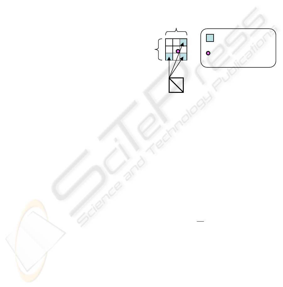
3.1 Degenerate Polygons as Glare
Sensors
Figure 3 illustrates how we use degenerate polygons
as glare sensors and create glare polygons.
Conceptually a degenerate polygon is a quad with no
size and it consists of 4 vertices. Each vertex has the
same screen coordinate values, the same texture
coordinate values for detecting bright pixel on the
screen. Each vertex also has different texture
coordinate values for glare images and different 2D
directional vector for expanding the polygon. Each
vertex of a degenerate polygon checks the luminance
value of the pixel of the scene using VTF
functionality.
VTF is a functionality to access texture
memories from vertex shaders which was introduced
as part of shader model 3.0 of Direct3D, and is
currently supported by NVIDIA GeForce 6 and later
GPUs. One examples of VTF functionality is what
is called displacement mapping where each vertex is
displaced according to some values stored in texture
memory. There are not yet many examples to show
the potential of VTF, and we expect our method to
pass1
pass2
pass3
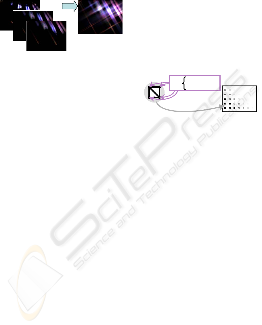
Figure 2: Multiple passes of blur filters for cross glare
images (Kawase, 2003).
Same 2D coordinate
Texture coordinate
Locate many on the screen
as glare sensors
Degenerate Polygon
Figure 3: Degenerate polygons as glare sensors.
REAL-TIME RENDERING OF HIGH QUALITY GLARE IMAGES USING VERTEX TEXTURE FETCH ON GPU
21
be one of the very few. Care must be taken when
using VTF because it is much slower than texture
fetching by pixel shaders. Also, current
implementation of VTF by NVIDIA has the
limitation that vertex shaders can only read textures
with 32bit floating point format.
As a glare sensor, one degenerate polygon
checks the assigned pixel in the rendered scene and
decides if the luminance value of the pixel is above
the threshold. If the pixel is considered bright
enough, each vertex of the degenerate polygon
moves itself away from its original position to
expand the quad to form a square to be used a glare
polygon where the glare image is put on. If the
assigned pixel is not bright enough, the degenerate
polygon will be ignored at the rasterizing stage.
3.2 Rendering of Glare Polygons
Once a degenerate polygon expands itself and
becomes a glare polygon, pixel shaders put a
translucent glare texture on the square polygon to
generate a glare image. Each vertex of the glare
polygon has unique texture coordinate values for
glare texture, i.e. (0, 0), (1, 0), (0, 1) and (1, 1) so
that the glare texture image will fit into the square
glare polygon.
Glare polygons are then rendered to a target
texture which will be later synthesized with the
original scene. When there are many bright pixels in
the original scene, rendering of many overlapping
translucent glare textures pushes the memory
bandwidth to the limit and this rendering stage
becomes the performance bottleneck.
Following the above idea, we can generate very
high quality glare images. But straight forward
implementation of the described method is not
practical for current GPUs. As described above,
when there are so many bright pixels in the original
scene, there will be so many overlapping translucent
glare polygons and rendering the whole scene is
sometimes as slow as a few fps. In the next section,
we will describe some performance enhancement
techniques of our method without sacrificing the
final glare image quality.
4 PERFORMANCE
ENHANCEMENT
TECHNIQUES
In this section we describe some important
techniques to improve performance of our basic
method. The basic strategy is to reduce the number
of translucent glare polygons as many as possible
without sacrificing the final image quality. The
technique to reduce the number of redundant VTF is
also described.
4.1 Grouping Glare Polygons
The first step to reduce the number of glare polygons
is to group some neighbouring glare polygons and
replace them with one new glare polygon where
possible. Assume we are going to group NxN
neighbouring pixels. (see Figure 4) To maintain
consistency, we set the luminance value of the new
glare polygon to be the sum of all luminance values
of the neighbouring pixels. We also adjust the
center position of the new glare polygon taking in to
consideration the distribution of luminance value
over the neighbouring pixels. The new luminance
value L
0
and the new center position P
0
of the new
glare polygon is defined by the following equation.
If we are to group 2x2 neighbouring pixels and
create one glare polygon for these pixels, we can
reduce the number of glare polygons to 1/4
compared to the number of polygons before
grouping. This reduction result in big performance
gain because we are limited by pixel fill rate of GPU.
Adjustment of new glare position works great for
chasing a small moving pixel. From visual tests by
many users, we can safely group 4x4 pixels using
this technique and still maintain high quality of the
final glare images.
0
1
0
1
0
...............(1)
1
NN
i
i
NN
ii
i
LL
PLP
L
×
=
×
=
⎫
=
⎪
⎪
⎬
⎪
=
⎪
⎭
∑
∑
g
Bright pixel
Center position
of glare polygon
N
N
Degenerate polygon
Figure 4: Grouping NxN Pixels for one glare polygon.
GRAPP 2006 - COMPUTER GRAPHICS THEORY AND APPLICATIONS
22
Notice that the number of vertices was reduced
to 1/NxN, but each vertex now has to check for NxN
pixels for the calculation of L
0
and P
0
, and the total
number of VTF in the scene remains the same. To
reduce the cost of 4 vertices of one degenerate
polygon accessing the same group of NxN pixels
using costly VTF, we now replace this process by a
pixel shader program which can read textures much
faster than using VTF. We first run a pre-processing
by a pixel shader program to read all NxN pixels,
calculate L
0
and P
0
values and store them in the new
render target texture. Now each vertex of
degenerate polygons has to read only one texel from
the texture just created to get L
0
and P
0
values. This
reduces the number of costly VTF down to 4/(NxN).
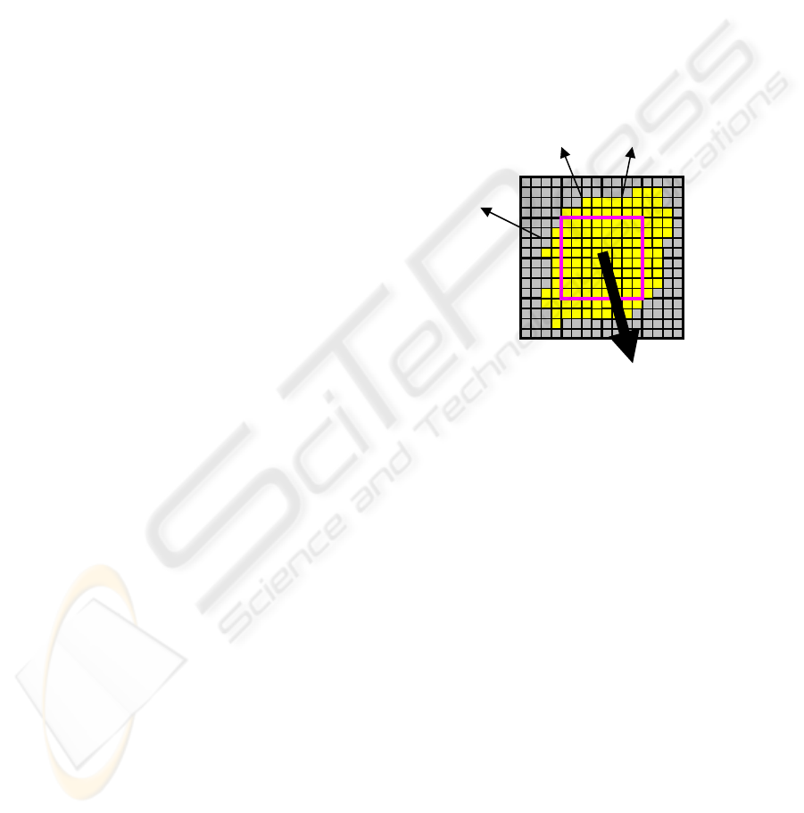
4.2 Clustering of Bright Pixel Areas
The above technique to reduce the number of glare
polygons works great to achieve significant speed
gain. We can stably achieve enough frame rates in
most cases, but in some very extreme situation
where the scene is mostly covered by bright areas,
there will be too many overlapping translucent
polygons to slow down the rendering speed. One
example of this is rendering of very bright sky
covering wide area of the scene.
To maintain decent frame rate even in such
extreme situation, we further group glare polygons
to cover fairy wide area of bright pixels. Figure 5
illustrates the basic idea of this approach. If more
than 90% of the pixels in 8x8 pixel area are bright
enough to cause glare effect, we put one glare
polygon for this area and prohibit expansion of other
degenerate polygons in the same area. Luminance
value and center position of the glare polygon can be
calculated by the equation (1) presented before. If
the above 8x8 area was not filled with enough
number of bright pixels, we do not create a glare
polygon for the area and let other 4 degenerate
polygons in the area do the job. This hierarchical
organization of glare polygons works great to reduce
the number of polygons and to maintain good frame
rate.
4.3 Shrinkage of Glare Polygons
To be physically correct, glare image keeps its size
on the screen independent of the luminance value.
The image just gets dimmer when the luminance
gets lower, but never gets smaller. Glare images
often have brightest pixels at their center where the
light source is, and get dimmer towards the outer
edge. When the luminance value of the glare image
gets dim enough, image around the edge gets
imperceptive to human eyes, and we can safely
discard these dark areas by shrinking glare polygons.
When shrinking a glare polygon, care must be
taken not to scale down the glare image drawn on
the screen. Shrinking a glare polygon without
scaling down the glare image requires linear
adjustment of texture coordinate values at each
vertex of the glare polygon according to the size of
the shrunk polygon. When to start shrinking and
how much we can safely shrink for certain
luminance value depends totally on luminance
distribution of the glare image, but this can be
precomputed. Shrinking glare polygons where
possible reduces unnecessary overlapping of too
dark glare images and we can gain some speed in
some cases.
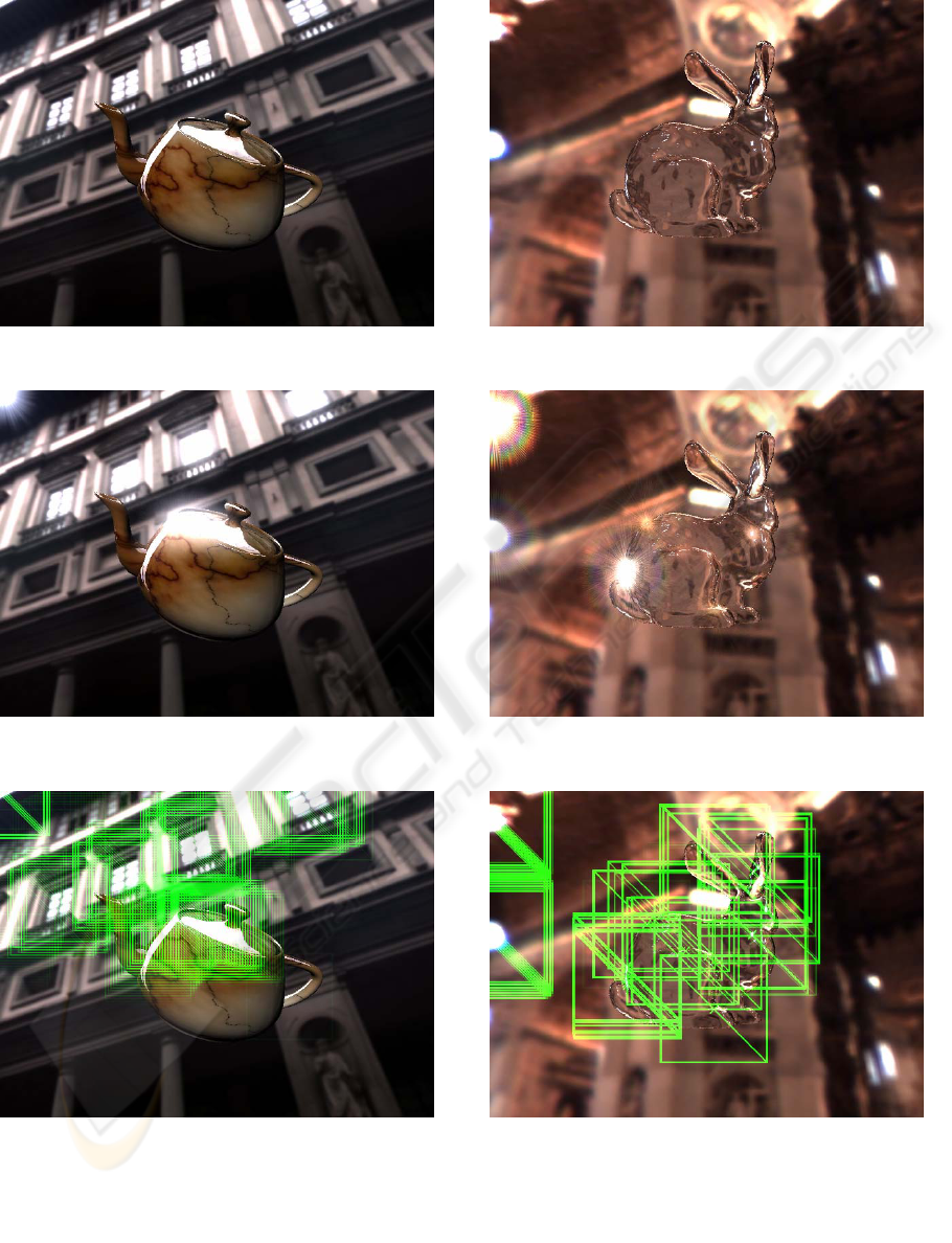
4.4 Performance Evaluation
By combining all these techniques, we achieved
drastic performance improvement over straight
forward implementation of our basic method. We
used NVIDIA GeForce 7800 GTX GPU with HLSL
of DirectX9 to render 1024x786 size scenes with
glares. The size of glare images used was 512x512.
Some of the images are shown in Figure 6. The
images at the top are the original scenes without
glare images, those in the middle are with glare
images and those on the bottom show the edges of
glare polygons. It can be seen that degenerate
polygons with VTF works great to create high
quality glare images at proper locations. Rendering
speed was above 60 fps in average, over 120 fps in
the best case, and 40 fps in the worst case. This
depends mostly on how many glare polygons were
drawn on the screen.
One Glare
One Glare
One Glare One Glare
Figure 5: Clustering of bright pixel areas.
REAL-TIME RENDERING OF HIGH QUALITY GLARE IMAGES USING VERTEX TEXTURE FETCH ON GPU
23

5 CONCLUSIONS
We have presented a new method for real-time
rendering of high quality glare images using the
latest vertex texture fetch technique. The basic idea
is to put degenerate polygons on the screen as
sensors to detect bright pixels and make them
expand to form glare polygons where glare images
are put. We have also presented some techniques to
improve rendering performance without sacrificing
image quality. It is fast enough for truly interactive
applications like computer games and virtual
environment. Combined with proper tone mapping
at the last rendering stage, the generated scene looks
pretty realistic. We will be using this technique for
such applications to enhance visual quality and
visual experience of the users.
You can replace degenerate polygons with point
sprites to reduce the number of VTF and save video
memory space. As VTF is not the performance
bottleneck, rendering speed gain is negligible.
Using our degenerate polygons, rotation of glare
images can be done by vertex shaders at almost no
cost. Rotation of glare images needs to be done by
costly pixel shaders when using point sprites. We
recommend to use point sprites only if the GPU
memory is limited, i.e. GPUs in game consoles, and
rotation of glare image is not necessary. There are
many tuneable parameters to gain rendering
performance and we do not have enough space to
describe this in detail, such as usage of texture
channels.
In this paper we described our method for glare
image rendering, and we are currently working on
generating so called “Lens Flare” effects. We can
use the same VTF technique with degenerate
polygons, but we need many polygons for a set of
lens flare images. Our technique works for any type
of glare images including sharp radial streaks and
blurry circles. Although creation of glare images is
not the main theme of this paper, we need a good
tool to create high quality glare images for high
quality rendering.
ACKNOWLEDGEMENTS
The glare image (a) in Figure 1 is cortesy of Dr.
Masanori Kakimoto. The glare images in Figure 2
are cortesy of Mr. Masaki Kawase. The HDR
environment maps in Figure 6 are couresy of Prof.
Paul Debevec. This research work is partly
supported by Grant for Promotion of Research from
University of Yamanashi
REFERENCES
Spencer, G., 1995 P. Shirley, K. Zimmerman, D. P.
Greenberg, “Physically-Based Glare Effects for
Digital Images”, In Proc. SIGGRAPH ’95, August
1995, pp. 325–334.
P. Rokita, “A Model for Rendering High Intensity Lights”,
Computers & Graphics, Vol. 17, No. 4, 1993, pp. 431–
437.
P. E. Debevec, J. Malik, “Recovering High Dynamic
Range Radiance Maps from Photographs”, In Proc.
SIGGRAPH ’97, August 1997, pp. 369–378
M. Kakimoto, Kaoru Matsuoka, Tomoyuki Nishita,
Takeshi Naemura, Hiroshi Harashima, “Glare
Generation Based on Wave Optics”, Computer
Graphics Forum, Vol. 24, No. 2, pp. 185-193, July
2005.
J. L. Mitchell, “RADEON 9700 Shading”, State of the Art
in Hardware Shading, Course Note #17, SIGGRAPH
’02, July 2002.
M. Kawase, M. Nagatani, “Real Time CG Rendering
Techniques Used in DOUBLE-S.T.E.A.L”,
CEDEC2002: CESA Game Developers Conference
2002, No. 1-3-A, Tokyo, September 2002.
M. Kawase, "Frame Buffer Postprocessing Effects in
DOUBLE-S.T.E.A.L (Wreckless)", Game Developers
Conference 2003 (GDC 2003), March 2003.
E. Reinhard, M. Stark, P. Shirley, J. Ferwerda,
"Photographic Tone Reproduction for Digital Images",
In Proc. SIGGRAPH 2002, July 2002, pp. 267-276.
R. L. Cook, T. Porter, L. Carpenter, “Distributed Ray
Tracing”, In Proc. SIGGRAPH ’84, 1984, pp. 137-
146.
P. E. Haeberli, K. Akeley, “The Accumulation Buffer:
Hardware Support for High-quality Rendering”, In
Proc. SIGGRAPH ’90, August 1990, pp. 309-318.
J. Santamaria, P. Artal, J. Bescos, “Determination of the
Point-Spread Function of Human Eyes Using a Hybrid
Optical Digital Method”, Optical Society of America
A, Vol. 4, No. 6, 1987, pp. 1109-1114.
S. Mostafawy, O. Kermani, H. Lubatschowski, “Virtual
Eye: Retinal Image Visualization of the Human Eye”,
IEEE CG&A, Vol. 17, No. 1, 1997, pp. 8-12.
C. Kolb, D. Mitchell, P. Hanrahan, “A Realistic Camera
Model for Computer Graphics”, In Proc. SIGGRAPH
’95, August 1995, pp. 325-334.
P. Gerasimov, R. Fernando, S. Green, "Shader Model 3.0
Using Vertex Textures", NVIDIA Corporation
Whitepaper, 2004.
J. D. Owens, D. Luebke, N. Govindaraju, M. Harris, J.
Krüger, A. E. Lefohn, T. J. Purcell, "A Survey of
General-Purpose Computation on Graphics Hardware",
In Proc. Eurographics 2005, State of the Art Reports,
August 2005, pp. 21-51.
GRAPP 2006 - COMPUTER GRAPHICS THEORY AND APPLICATIONS
24
(a1)
(a2)
(a3)
(b1)
(b2)
(b3)
Figure 6: TOP (a1,b1) Original scenes without glare image, MIDDLE (a2, b2) Scenes with glare images generated with
our method, BOTTOM (a3, b3) Glare polygons rendered as green squares to show their locations.
REAL-TIME RENDERING OF HIGH QUALITY GLARE IMAGES USING VERTEX TEXTURE FETCH ON GPU
25
