
A COMPARISON OF CYLINDRICAL PASTING METHODS
Shalini Aggarwal
Computer Graphics Laboratory
University of Waterloo
Stephen Mann
Computer Graphics Laboratory
University of Waterloo
Keywords:
Tensor product B-splines, hierarchical modeling, surface pasting.
Abstract:
In this paper, we study six different boundary control point mappings for cylindrical surface pasting and
compare the resulting pasted surfaces for C
0
join continuity. All six methods are algorithmically simple
with low computational costs, requiring minimal computation aside from surface evaluation. The results
demonstrate an order of magnitude quality improvement for some of our methods on a convex-only curved
base, however, as the complexity of the base surface increases all methods show similar performance.
1 INTRODUCTION
The ability to construct smooth composite surfaces
with multiple levels of control and adjustability, that
can be modified or animated at interactive rates, is
important to the modeling industry and to computer
aided geometric design research. Hierarchical model-
ing offers a conceptual basis for generating surfaces
with varying levels of detail. The surface building
blocks are typically tensor product B-spline surfaces,
preferred for their flexibility, compact representation
and adjustable levels of internal continuity. Tradi-
tional methods for adding local detail to tensor prod-
uct B-spline surfaces are knot insertion or degree rais-
ing, which increase complexity of the entire surface.
Instead, hierarchical modeling techniques such as hi-
erarchical B-splines (Forsey and Bartels, 1988), cer-
tain wavelet methods (Stollnitz et al., 1996), displace-
ment mapping (Foley et al., 1990) and surface pasting
(Bartels and Forsey, 1991; Barghiel et al., 1995) op-
erate locally.
Surface pasting was introduced by Bartels and
Forsey (Bartels and Forsey, 1991) to mimic the phys-
ical process of modeling with clay. It places a tensor
product B-spline surface called the feature, on top of
a tensor product B-spline surface hierarchy known as
the base, via a smart mapping of feature control points
onto the base. Surface pasting has a couple advan-
tages over other known hierarchical modeling tech-
niques — it offers lower computational costs, lower
storage requirements, easy repositioning, and flexibil-
ity of non-parametric alignments. At the same time,
because of the approximations involved in mapping a
feature onto its base, a pasted feature is not guaran-
teed to meet its base surface with any order of conti-
nuity at the join boundary.
Original surface pasting focused upon constructing
hierarchical surfaces comprised only of tensor prod-
uct patches. The standard algorithm then utilized the
linearity of patch boundary control points to minimize
join discontinuities.
Cylindrical surface pasting was introduced by
Mann and Yeung (Mann and Yeung, 2001) to extend
the scope of pasting to model surfaces that include
tensor product cylinders. In their work, the process
of pasting a cylindrical feature’s boundary onto a
base surface was accomplished using the same ap-
proximations used by standard surface pasting. How-
ever, a fundamental construction difference between
the closed curve boundary of a tensor product cylin-
der and the linear boundary of a tensor product patch
leads us to believe that we can do better than this di-
rect application.
In this paper, we propose and examine five alter-
native cylindrical pasting techniques that attempt to
account for the cylindrical feature’s structural dif-
ference. Previous work has been done to improve
pasted surface quality by incorporating approxima-
tion schemes such as quasi-interpolation (Conrad and
Mann, 2000), least-squares fittings (Leung and Mann,
2003) and Greville point interpolation (Siu and Mann,
2003); the first two of these extensions having only
108
Aggarwal S. and Mann S. (2006).
A COMPARISON OF CYLINDRICAL PASTING METHODS.
In Proceedings of the First International Conference on Computer Graphics Theory and Applications, pages 108-115
DOI: 10.5220/0001353901080115
Copyright
c
SciTePress

been examined in the context of patch pasting. In
the context of cylindrical pasting these implementa-
tions are expected to suffer from high evaluation costs
and/or significant algorithmic complexities. Our work
focuses upon determining a cylindrical pasting tech-
nique that is computationally inexpensive, simple to
implement, and that consistently gives the best com-
parative approximation of boundary continuity (i.e.,
C
0
continuity) between a pasted feature cylinder and
its underlying base surface. In a more general sense,
our work attempts to find a low-cost method of using
a given closed B-spline curve to approximate a dif-
ferent given closed curve, with minimal reproduction
error.
2 PASTING BASICS
We begin with an overview of surface pasting theory
since it forms the foundation for the work done in this
paper. Surface pasting combines a base surface and a
feature surface, each of which is in tensor product B-
spline form and defined over its own two-dimensional
domain. The basic idea is to adjust the feature’s con-
trol points in a manner that results in the boundary of
the pasted feature lying on or near the base surface,
while simultaneously ensuring that the shape of the
pasted feature reflects characteristics of both its orig-
inal form as well as of its base. To achieve this, the
pasting process involves the following steps:
1. The feature’s domain is embedded into its range
space. Tensor product construction ensures that
each feature control point P
i,j
has an associated
domain point at which it maximally influences the
feature surface. This domain point is referred to
as the Greville point (γ
i
,γ
j
)=γ
i,j
, where γ
i
is
the i
th
Greville abscissa in the u parametric di-
rection and γ
j
is the j
th
Greville abscissa in the
v direction. Taking the embedded Greville point
(γ
i,j
, 0) = Γ
i,j
in feature range space as a point of
origin, and using the feature’s corresponding para-
metric domain directions to define a set of basis
vectors, a local coordinate frame associated with
each P
i,j
is constructed. Now, each feature control
point can be expressed relative its local coordinate
frame in terms of a displacement from its origin
called the Greville displacement
d
i,j
.
2. The feature domain is mapped into the base domain
using an invertible transformation T . T determines
the relative size and placement of the feature sur-
face with respect to its base.
3. A base domain displacement representation of each
feature control point is created by expressing each
displacement
d
i,j
in terms of a local base coordi-
nate frame.
4. The feature control points are positioned relative
to the base surface using the local base coordinate
frame and the mapped displacement vector recom-
puted relative to this frame.
Note that surface pasting is only an approximation
technique. Rather than mapping every point of the
feature surface, it maps a small number of sample
sites, the feature Greville points. If the feature sur-
face is described by too few control points or a coarse
knot structure relative to its base, noticeable gaps at
the join boundary may appear in the composite sur-
face. In general, there is no guaranteed continuity be-
tween feature and base surfaces.
In the case of standard surface pasting, C
0
continu-
ity is approximated by defining the embedded feature
domain such that all boundary control points of the
feature coincide with their respective Greville points.
This ensures that the feature’s boundary control points
lie in the feature’s domain plane and that upon being
pasted they will lie directly on the base surface. Pro-
vided the base has low curvature relative to the spac-
ing between these points, a near C
0
join is achieved.
For further details on standard surface pasting, refer
to earlier works on the subject (Bartels and Forsey,
1991; Barghiel et al., 1995).
Cylindrical surface pasting integrates concepts
from parametric trimline-based blending to extend
surface pasting to handle a wider variety of modeling
situations. While standard pasting was designed only
to handle the pasting of one open surface atop another,
cylindrical pasting offers a method for connecting two
base surfaces smoothly using a tensor product cylin-
der as the feature surface. In this paper, we are only
concerned with pasting one end of a cylinder onto a
base tensor product surface.
To paste one end of a cylindrical feature onto
its base surface, the corresponding edge of the fea-
ture domain is mapped onto a paste curve in the
base domain. Determining the placement of con-
trol points such that the pasted cylinder’s boundary
closely matches the image of a user-defined paste
curve on the base surface is our challenge. The orig-
inal cylindrical pasting technique directly applied the
C
0
continuity approximation of standard surface past-
ing to the C
0
layer of a feature cylinder, i.e., each
boundary control point was located at its correspond-
ing Greville point. However, while zero displacement
control points reproduce the linear boundary of a ten-
sor product patch, placing the control points on the
closed curve boundary of a tensor product cylinder
does not reproduce its boundary (Figure 1). Our work
explores alternate methods that have the potential of
producing better C
0
continuity between the pasted
cylinder and its underlying base. To maintain the
prototyping nature of pasting, the methods we have
designed have low computational costs, with a paste
not costing much more than one base surface evalua-
A COMPARISON OF CYLINDRICAL PASTING METHODS
109
tion per boundary control point. We have limited our
study to algorithmically simple techniques, as our in-
tent was also to establish a standard for pasting the
boundary of a cylindrical feature.
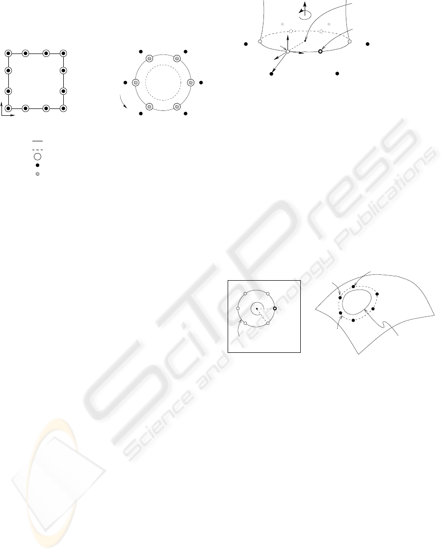
control points placed at a zero greville displacement
v
Cylindrical Pasting
v
u
shifted curve given by hashed control points
control points describing the original curve
image of original curve greville points
Patch Pasting
original curve given by filled control points
Figure 1: Greville displacement of boundary control points
set to zero.
3 BOUNDARY CONTINUITY IN
CYLINDRICAL PASTING
The results of pasting the boundary of a feature cylin-
der onto a base surface depend upon the feature-to-
base space mappings used. We have examined four
types of mappings (with minor variations on two of
them), which we present here. Our method discus-
sions assume that a given m × n tensor product fea-
ture cylinder C(u, v)=
M
i=0
N
j=0
P
i,j
N
i,j
(u, v),
as shown in Figure 2, is being pasted onto the sur-
face of a tensor product base B(u, v) along the cylin-
der’s L
0
: u = u
0
edge. The pasted feature boundary
is to be constructed as an approximation to a curve
on the base surface called the trim curve. The trim
curve is a mapping into base range space of a user-
defined circular paste curve given in the base domain.
Although a polynomial paste curve could have been
used, working with a circular representation allows
for simpler implementations while still providing use-
ful paste-quality comparisons (Aggarwal, 2004).
3.1 Greville Paste
The Greville Paste method is similar in concept to
the technique described in the original work on cylin-
drical pasting. It assumes that the feature cylinder’s
boundary control points and its corresponding sur-
face Greville points coincide, i.e., the boundary con-
trol points lie on the cylinder’s edge. As discussed in
§2, this assumption will inevitably result in a gap be-
tween the pasted cylinder boundary and the base sur-
face trim curve. Although this cylindrical pasting C
0
v
u
ˆ
F
y
j
C(γ
0,j
)
barycentre of
surface Greville points,
C(γ
0,0
)=C(γ
0,N −2
)
d
j
= a
ˆ
F
x
j
+ b
ˆ
F
y
j
+0
ˆ
F
z
j
surface Greville point,
C
c
P
0,j
L
0
control point, P
0,0
= P
0,N −2
ˆ
F
z
j
ˆ
F
x
j
Figure 2: Feature Cylinder C(u, v).
continuity approximation seems less than acceptable,
the Greville Paste method is useful as a comparative
base case method. In particular, one can expect its
application to yield three things:
1. a minimum cost metric: it requires only one surface
evaluation per boundary control point
2. a maximum acceptable error bound
3. a well-defined convergence: upon infinite refine-
ment the pasted control points will define the trim
curve exactly.
pasted feature boundary
paste curve
pasted L
0
control points
t
0
θ
j
γ
0,j
= t
j
Base Domain
trim curve
P
0,j
= B(γ
0,j
)
Base Surface B(u, v)
user-defined
Figure 3: Greville Paste.
To describe the Greville Paste process we use Fig-
ure 3. We start by embedding the feature cylinder’s
L
0
surface Greville points {C(γ
0,j
)}
N−3
j=0
into the
base domain. The embedded Greville points γ
0,j
are
obtained by a simple placement of each γ
0,j
onto a
corresponding paste point t
j
given on the paste curve
in the base domain’s uv-plane. The paste point t
0
is
chosen relative to the centre of the paste curve circle
at an angle of zero degrees to the u-parametric direc-
tion of the base domain, and the remaining t
j
s are
then determined in proportion to the v-interval of the
cylinder’s domain. Now, each C(γ
0,j
) can be mapped
onto the base surface by performing a de Boor surface
evaluation of the base at its embedded Greville point,
giving the pasted Greville point B(γ
0,j
). Placing the
feature cylinder’s L
0
control points at the pasted Gre-
ville points with zero displacement results in a set of
pasted control points P
0,j
= B(γ
0,j
), which are used
to describe the cylinder’s pasted boundary.
GRAPP 2006 - COMPUTER GRAPHICS THEORY AND APPLICATIONS
110
3.2 Control Point Paste
Control Point Paste is the first of three new cylin-
drical pasting techniques we devised, that attempt
to better account for the non-zero Greville displace-
ments of cylinder control points. Under Control Point
Paste, the embedded location of each cylinder control
point within the base domain is determined as the sum
of its associated embedded Greville point and trans-
formed Greville displacement vector. Implementation
specifics are illustrated in Figure 4.
points
s
j
x
pasted feature boundary
Base Surface B(u, v)
P
0,j
= B(p
j
)
trim curve
t
j
initial paste points
paste curve
s
j
y
Base Domain
p
j
= t
j
+ α(aˆs
x
j
+ bˆs
y
j
)
pasted L
0
control
Figure 4: Control Point Paste.
The first step is to determine the L
0
Greville dis-
placement vectors
d
j
(Figure 2). For each control
point P
0,j
,
d
j
is computed with respect to a unique
local coordinate frame F
j
, constructed such that
• F
O
j
, the origin of F
j
, is at its corresponding surface
Greville point: F
O
j
= C(γ
0,j
)
•
ˆ
F
x
j
is given by a unit normal along the differ-
ence vector between the surface Greville point and
the centre of the cylinder’s L
0
edge (C
c
, deter-
mined using Ceva’s Theorem (Wells, 1991)) as:
ˆ
F
x
j
=
F
O
j
−C
c
|F
O
j
−C
c
|
•
ˆ
F
y
j
is given by the normalized tangent to the cylin-
der’s boundary curve at the chosen origin, and is
along the v-parametric direction; this is also the di-
rectional derivative obtained by a de Boor evalua-
tion of the L
0
curve
•
ˆ
F
z
j
is given by a unit vector perpendicular to both
ˆ
F
x
j
and
ˆ
F
y
j
.
The coordinates of each control point in relation to
this local frame give the xyz components of the Gre-
ville displacements. By construction, the tensor prod-
uct cylinders we use are such that the control points
within each u-layer are coplanar, therefore, the z-
component is always zero.
The initial paste points t
j
on the base domain paste
curve are determined as they were for the Greville
Paste method. These are the locations at which we
would like our mapped L
0
surface Greville points to
lie. So, using our
d
j
s we compute a relative place-
ment of feature control points within the base domain
space. In particular,
ˆ
F
x
j
is mapped to ˆs
x
j
, the out direc-
tion at t
j
given by the 2D difference vector between t
j
and the circular paste curve’s centre point.
ˆ
F
y
j
maps
to ˆs
y
j
along the tangent to the paste curve at t
j
.To
account for the space change, a scale factor α, equal
to the ratio of paste curve to cylinder curve radii is
used. Applying the proportional displacement gives
the paste points p
j
within the base domain. De Boor
evaluations at the p
j
s produce the set of pasted control
points P
0,j
= B(p
j
) describing the pasted cylinder
boundary using Control Point Paste.
Applying a 3D displacement within a 2D domain
space results in pasted control points that lie on the
base surface; however, the resulting pasted cylinder
edge is unlikely to lie on the base unless the paste
region is planar. A potential way to avoid errors in-
troduced by 3D-in-2D computations is to account for
the feature’s L
0
Greville displacements in the 3D base
range space instead. This alternative is explored using
the next method.
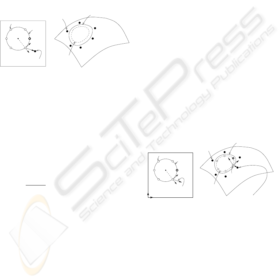
3.3 Directional Displacement Paste
Directional Displacement Paste attempts to reduce C
0
gaps by computing the pasted control point locations
relative to points on the trim curve in the base range
space. The details, in context of Figure 5, follow.
s
j
= α(aˆs
x
j
+ bˆs
y
j
)
= ku + lv
P
0,j
= B(t
j
)+k∂u + l∂v
= B(t
j
)+αa∂ˆs
x
j
+ αb∂ˆs
y
j
points
pasted L
0
control
s
j
x
v
t
j
s
j
y
paste curve
u
initial paste points
trim curve
∂u
j
t
j
= B(t
j
)
∂v
j
pasted feature boundary
Base Domain Base Surface B(u, v)
Figure 5: Directional Displacement Paste (Local).
Evaluating the base surface at points t
j
generates a
set of points t
j
lying on the trim curve. Ideally, the
pasted cylinder boundary will be placed exactly on
top of this trim curve. This suggests that the pasted
cylinder edge should be constructed such that all the
trim points t
j
lie on it. By definition, surface Gre-
ville points lie on the surface they describe. There-
fore, Directional Displacement Paste maps the L
0
sur-
face Greville points onto the trim points. The cylin-
der’s pasted L
0
control points are then computed by
placing them relative to these pasted Greville point
A COMPARISON OF CYLINDRICAL PASTING METHODS
111

locations. The displacements are determined using
the L
0
Greville displacement vectors
d
j
(§3.2), which
are mapped through the base domain (s
j
) onto the
base surface. A point-vector addition of transformed
feature-to-base space L
0
Greville points and Greville
displacements gives the pasted cylinder’s boundary
control points.
A potentially useful modification to Directional
Displacement Paste came about from observing the
performance of the above described method on ini-
tial test data. Over a hump-like paste region, the
high surface curvature at the trim points displaced
the control points in a manner that pushed the pasted
feature boundary well below the base surface trim
curve. Therefore, we examined the pasting behavior
when the displacements are computed using a simple
approximation of average surface curvature over the
paste region instead of local curvature.
To incorporate an average surface curvature, we
perform a mapping of the paste curve’s centre point
onto the base, and compute base surface directional
derivatives at it. The pasted boundary control point
locations are then determined by applying the corre-
sponding Greville displacement vector’s components
along the centre point’s uv-directional vectors. The
local directional derivatives at each t
j
no longer need
to be computed. We refer to our original technique
as Local Directional Displacement and the modified
method as Average Directional Displacement.
3.4 Relative Displacement Paste
Relative Displacement Paste was motivated by Direc-
tional Displacement Paste. It too attempts to compute
the L
0
pasted cylinder control points by accounting
for Greville displacements in the base range space.
The difference is in how the displacement frame is
constructed at each mapped cylinder Greville point on
the base. Directional Displacement mapped each fea-
ture surface displacement frame F
j
onto the base sur-
face via the 2D base domain space (Figure 5). How-
ever, this mapping does not maintain the relation-
ship of displacement frame directions to correspond-
ing feature boundary points when the shape of a cylin-
der’s L
0
boundary curve distorts with pasting. Rela-
tive Displacement Paste maps the feature surface dis-
placement frame directly onto the base surface so as
to maintain the original F
j
relationships to the feature
boundary.
We describe this method in relation to Figure 6.
For all j = {0,...,N − 3}, F
j
,
d
j
, γ
0,j
= t
j
, and
t
j
= B(t
j
) are computed exactly as for Directional
Displacement Paste (§3.3). The pasting displacement
frame S
j
at each t
j
is then constructed such that
•
ˆ
S
x
j
is the unit difference vector between t
j
and the
new barycentre of pasted Greville points;
barycentre of
pasted L
0
control
points
pasted Greville
points
paste curve
γ
0,j
= t
j
ˆ
S
y
j
ˆ
S
x
j
pasted feature boundary
trim curve
Base Surface B(u, v)Base Domain
t
j
= B(t
j
)
P
0,j
= B(t
j
)+βa
ˆ
S
x
j
+ βb
ˆ
S
y
j
Figure 6: Relative Displacement Paste (Average).
•
ˆ
S
y
j
is the normalized tangent to the trim curve at t
j
,
given by the difference of slopes between t
j
and its
two neighboring pasted Greville points.
The local frame directions
ˆ
F
x
j
and
ˆ
F
y
j
are now
mapped to
ˆ
S
x
j
and
ˆ
S
y
j
respectively. The xy compo-
nents of
d
j
, i.e., a and b are applied along
ˆ
S
x
j
and
ˆ
S
y
j
respectively to give a control point placement relative
t
j
. A change of space scale factor β is applied to the
displacement vector to account for the transformation
from feature surface space to base surface space. β
is computed as the ratio of the average distance be-
tween original L
0
surface Greville points and their
barycentre to the average distance between pasted sur-
face Greville points and their barycentre.
Two variations of Relative Displacement Paste
were examined — Average Relative Displacement
uses the barycentre of all {t
j
}
N−3
j=0
to compute
ˆ
S
x
j
,
whereas Local Relative Displacement uses a local
barycentre given by t
j
and its two neighboring pasted
Greville points. The rationale for the local method be-
ing that when the curvature of a base surface has more
noticeable variations over the paste region boundary,
locally affected
ˆ
S
x
j
s may offer a better placement of
the control points.
4 COMPUTATIONAL ANALYSIS
The most significant computational cost in surface
pasting is the number of base surface evaluations that
need to be performed to position the feature’s pasted
control points. One surface position evaluation per
L
0
cylinder control point is the minimum C
0
require-
ment for any cylindrical pasting method. An approxi-
mation improvement technique such as knot insertion
rapidly becomes unacceptable as it doubles the num-
ber of control points at each level of refinement, in-
creasing evaluation costs exponentially. The methods
we have described in this paper attempt to improve a
feature cylinder’s pasted boundary approximation of
GRAPP 2006 - COMPUTER GRAPHICS THEORY AND APPLICATIONS
112

the trim curve for relatively small increases in cost. A
comparative summary of pasting costs per boundary
control point is given in Table 1 (refer to (Aggarwal,
2004) for a detailed analysis). It may be noted that
the cost of pasting a control point using any of our
methods is at most half as expensive as doubling the
number of control points using knot insertion to im-
prove the pasted join accuracy. To keep the relative
costs in perspective, we note that a de Boor position-
only surface evaluation for a bicubic tensor product
surface requires 30 affine combinations, a position-
with-derivatives evaluation takes 37 affine combina-
tions, and a vector difference of a pair of points is one
affine combination.
5 ERROR BOUNDS
To provide a bound on how fast the error in C
0
con-
tinuity is expected to converge with feature cylinder
refinement, we use the concept of linear reproduc-
tion. Given a polynomial function F and its approx-
imation P , a Taylor series expansion gives the error
as
∞
i=0
F
(i)
(ξ)−P
(i)
(ξ)
i!
h
i
. An interpolation method
is said to have linear precision if F (ξ)=P (ξ)
and F
(ξ)=P
(ξ). In this case, the first two
terms of the Taylor series cancel, leaving an error of
∞
i=2
F
(i)
(ξ)−P
(i)
(ξ)
i!
h
i
= O(h
2
), where h is the dis-
tance between samples. Standard surface pasting is
expected to have this property, as was verified empir-
ically by Conrad (Conrad, 1999).
Further mathematical analysis, as given in (Aggar-
wal, 2004), enables us to determine whether linear re-
production also holds for the cylindrical surface past-
ing methods described in this paper. Essentially, for
each scheme, we examine whether the pasted cylin-
der’s boundary is expected to be identical to its trim
curve on a linear base surface. The results of our the-
oretical analysis are summarized in Table 1.
6 RESULTS
The empirical error between the feature cylinder’s
pasted boundary and the base surface trim curve of-
fers an important comparison metric for evaluation of
the feature-on-base boundary quality. For our error
analysis, we examined the maximum position differ-
ence between these two closed curves, and the pro-
gressive refinement ratio of their differences describ-
ing the rate of error convergence. Our cylindrical
boundary pasting schemes were evaluated for three
different base surfaces of increasing complexity — a
planar base, a simple curved base, and a base with an
inflection. All the surfaces used (bases and feature
cylinder) were bicubic surfaces. We chose circular
paste curves defined by a center and radius in the base
domain. Also, our feature was constructed to have a
close-to-circular L
0
boundary.
C
0
continuity sampling information was generated
by sampling the pasted feature boundary at 10 dif-
ferent positions for each non-overlapping domain in-
terval in the cylinder’s v-parametric direction. These
points were compared against samples on the base
trim curve taken at points associated with each v-
parameter value of the cylinder domain. With each
level of feature refinement, the number of samples
taken was doubled.
Pasting the cylinder’s boundary onto a planar base
patch yielded a close to zero error for all methods ex-
cept Greville Paste. This is in keeping with the theo-
retical expectation of linear reproduction for all meth-
ods other than Greville Paste.
Pasting onto a curved, convex-only, bicubic base
that did not have any regions of negative Gaussian
curvature, gave results supporting quadratic error con-
vergence for all methods including Greville Paste. In
this case, Average Directional Displacement and both
Relative Displacement Paste methods were found to
perform a magnitude better than Greville Paste.
For our final test case, we pasted the boundary of
our feature cylinder onto a curved bicubic base over
a region of negative Gaussian curvature. Results are
given in Table 2 (Figure 7). The Relative Displace-
ment Paste methods appear to perform an order of
magnitude better when the feature knot structure is
approximately as coarse as that of the base. However,
one level of cylinder refinement improves Greville
Paste to be comparable to the Relative Displacement
techniques. The minor error reductions offered by the
alternatives to Greville Paste are clearly offset by their
extra computational costs. Further, even-though Gre-
ville Paste doesn’t have the linear reproduction prop-
erty, all our results indicate that it has O(h
2
) error
convergence. Therefore, it appears that as the com-
plexity of the base surface increases, the C
0
pasting
results obtained using Greville Paste are comparable
to all our other cylindrical pasting approaches.
7 CONCLUSION
In this paper, we have examined six different con-
trol point placements for describing the pasted cylin-
der boundary – Greville Paste, Control Point Paste,
Local Domain Displacement, Average Domain Dis-
placement, Local Relative Displacement, and Aver-
age Relative Displacement. Greville Paste was essen-
tially a direct application of the standard surface past-
ing algorithm to cylindrical pasting.
Greville Paste seemed intuitively inadequate for
A COMPARISON OF CYLINDRICAL PASTING METHODS
113
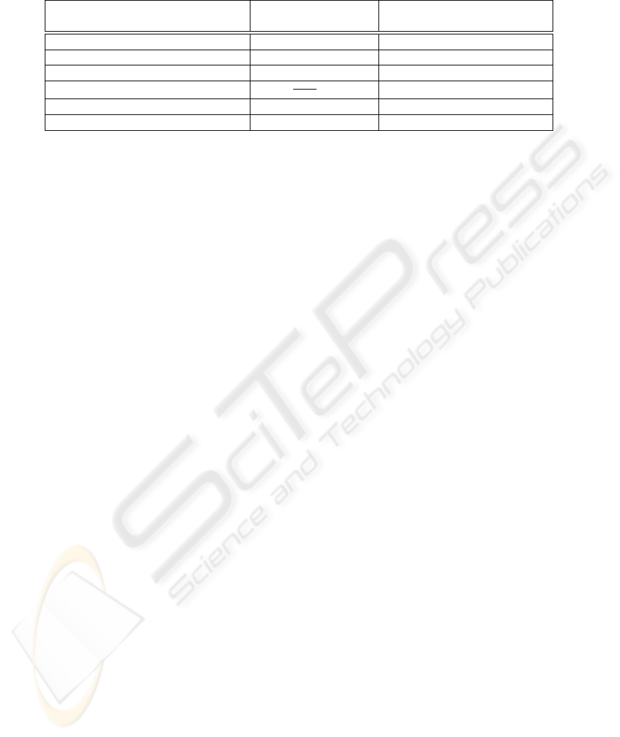
Table 1: Costs and linear reproducibility associated with pasting a m × 3 cylinder onto a bicubic patch. N is the number of
control points.
Method Affine combinations Linear reproduction satisfied
per control point
Greville Paste 30 no
Control Point Paste 40 yes
Local Directional Displacement 47 yes
Average Directional Displacement 40+
37
N−3
,N ≥ 9 yes
Local Relative Displacement 44 not necessarily
Average Relative Displacement 43 yes
pasting cylinders because its placement of pasted con-
trol points onto the desired join boundary could never
reproduce the corresponding closed curve. Based
upon the theory used in constructing our methods, we
expected that Local Domain Displacement would re-
sult in the most accurate C
0
paste for any base sur-
face irrespective of its complexity. Instead, an em-
pirical analysis of the error between the pasted cylin-
der boundaries and the desired trim curve indicates
that the less-intuitive Relative Displacement Paste
methods most consistently produce the best quality
join. However, the relative improvement over Gre-
ville Paste drops rapidly with every level of cylinder
refinement when pasting onto a complex base surface.
It comes as a surprise that, in general, Greville
Paste does as well as any of our other cylindrical
boundary pasting methods. Our results further con-
firm that the best possible error convergence offered
by the methods explored is quadratic in all cases.
Therefore, the original standard pasting technique is
a reasonable standard not only for patches, but also
for cylinders.
8 FUTURE WORK
Our work focused on establishing a simple and low-
cost cylindrical boundary pasting standard. It is rec-
ommended that another study be performed to as-
sess the results of cylindrical boundary pasting using
methods such as quasi-interpolation, least-squares fit-
ting, and Greville point interpolation. Although the
initial computation costs are expected to be notably
high for these methods, they may be effectively com-
pensated for by low re-evaluation costs when pasting
over the same region. The algorithmic complexity of
these alternate methods may still be a concern.
REFERENCES
Aggarwal, S. (2004). Comparison of cylindrical boundary
pasting methods. Master’s thesis, University of Wa-
terloo, Waterloo, Ontario, Canada N2L 3G1.
Barghiel, C., Bartels, R., and Forsey, D. (1995). Past-
ing spline surfaces. In Daehlen, M., Lyche, T., and
Schumaker, L., editors, Mathematical Methods for
Curves and Surfaces, pages 31–40. Vanderbilt Univer-
sity Press.
Bartels, R. and Forsey, D. (1991). Spline overlay surfaces.
Technical Report CS-92-08, University of Waterloo,
Waterloo, Ontario, Canada N2L 3G1.
Conrad, B. (1999). Better pasting through quasi-
interpolation. Master’s thesis, University of Waterloo,
Waterloo, Ontario, Canada N2L 3G1.
Conrad, B. and Mann, S. (2000). Better pasting via quasi-
interpolation. In Laurent, P.-J., Sablonni
`
ere, P., and
Schumaker, L., editors, Curve and Surface Design,
pages 27–36. Vanderbilt University Press.
Foley, J., vanDam, A., Feiner, S., and Hughes, J.
(1990). Computer Graphics Principles and Practice.
Addison-Wesley, second edition.
Forsey, D. and Bartels, R. (1988). Hierarchical B-Spline
refinement. In Computer Graphics (SIGGRAPH ’88),
volume 22(4), pages 205–212.
Leung, R. and Mann, S. (2003). Distortion minimization
and continuity preservation in surface pasting. In
Graphics Interface, pages 193–200.
Mann, S. and Yeung, T. (2001). Cylindrical surface pasting.
In Geometric Modeling, pages 233–248. Springer-
Wein.
Siu, S. and Mann, S. (2003). Computer aided ferret de-
sign. In Geometric Modeling and Graphics, pages
195–200. IEEE Computer Society.
Stollnitz, E., DeRose, T., and Salesin, D. (1996). Wavelets
for Computer Graphics: Theory and Applications.
Morgan Kaufmann, San Francisco.
Wells, D. (1991). The Penguin Dictionary of Curious and
Interesting Geometry. Penguin.
GRAPP 2006 - COMPUTER GRAPHICS THEORY AND APPLICATIONS
114
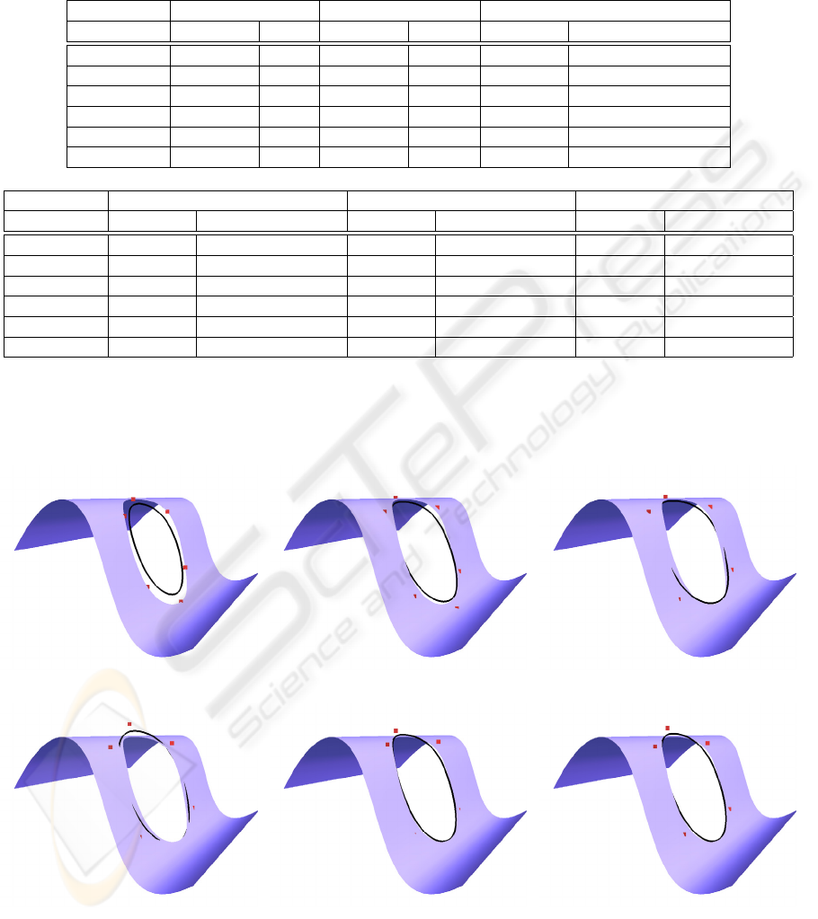
Table 2: Experimental errors from pasting a feature cylinder’s boundary onto a bicubic base over a region of negative Gaussian
curvature. The ratio in row i is the ratio of Max
i
to Max
i−1
for the corresponding method.
Greville Paste Control Point Paste Local Directional Displacement
Refinement Max Ratio Max Ratio Max Ratio
0 0.185416 na 0.067727 na 0.131738 na
1 0.049609 3.74 0.023591 2.87 0.037600 3.50
2 0.012585 3.94 0.006567 3.59 0.009219 4.08
3 0.003157 3.99 0.001600 4.10 0.002005 4.60
4 0.000790 4.00 0.000359 4.46 0.000473 4.23
5 0.000198 4.00 0.000089 4.05 0.000114 4.15
Avg Directional Displacement Local Relative Displacement Avg Relative Displacement
Refinement Max Ratio Max Ratio Max Ratio
0 0.123581 na 0.037246 na 0.039474 na
1 0.035348 3.50 0.014900 2.50 0.018923 2.09
2 0.008783 4.02 0.005125 2.91 0.004766 3.97
3 0.001984 4.43 0.001332 3.85 0.001232 3.87
4 0.000471 4.21 0.000299 4.45 0.000276 4.47
5 0.000113 4.18 0.000073 4.10 0.000067 4.10
(a) Greville Paste (b) Control Point Paste (c) Local Directional Displacement
(d) Average Directional Displacement (e) Local Relative Displacement (f) Average Relative Displacement
Figure 7: Pasting onto a curved bicubic base over a region of negative Gaussian curvature.
A COMPARISON OF CYLINDRICAL PASTING METHODS
115
