REAL-TIME IMAGE BASED LIGHTING FOR OUTDOOR
AUGMENTED REALITY UNDER DYNAMICALLY CHANGING
ILLUMINATION CONDITIONS
Tommy Jensen, Mikkel S. Andersen, Claus B. Madsen
Laboratory for Computer Vision and Media Technology, Aalborg University, Fredrik Bajers Vej 5, 9220 Aalborg East
Keywords: Augmented Reality, Rendering, Relighting, Image Based Lighting, Environment Map.
Abstract: Knowledge about illumination conditions in a real world scene has many applications, among them
Augmented Reality which aims at placing virtual objects in the real world. An important factor for
convincing augmentations is to use the illumination of the real world when rendering the virtual objects so
they are shaded consistently and cast consistent shadows. The work presented in this paper aims at making a
robust system capable of estimating the lighting of an outdoor scene, and apply the light changes to the
virtual augmented objects that are placed within a real scene. The method uses an Irradiance Volume,
modified to use an environment map of a given scene, to mimic the multiple lights reflected in a scene using
Image Based Lighting, while normal Phong shading is used to mimic the sun shading. These are combined
with a Shadow Volume method to ensure shadow interaction with the surrounding environment. For every
frame an Illumination Estimation approximates local illumination light parameters used in the rendering of
the augmented objects. The light parameters are furthermore used to, at runtime, create new environment
maps, to update the irradiance volume. The result is a rendering pipeline capable of handling dynamic light
changes, and applies them to augmented objects within a given scene, enabling realistic augmentations
under changing illumination conditions.
1 INTRODUCTION
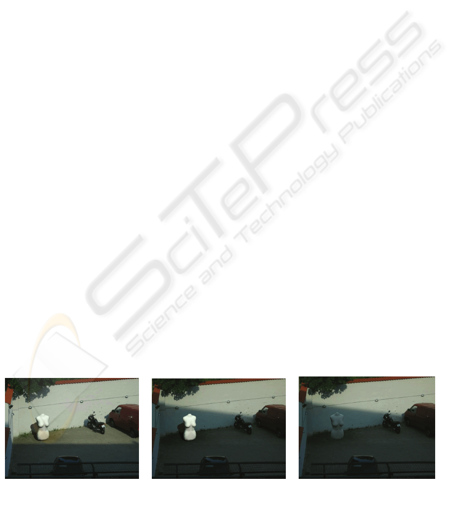
Picture a yard in your inner eye. In this yard a statue
has been placed that is bathed by the sun, and casts a
shadow on the ground. There is nothing in the image
pointing to the fact that the statue is not real.
Now a cloud suddenly blocks the sun, and the
lighting of the yard is dampened. But somehow the
statue seems to still be bathed in a sun with far more
intensity than the surroundings, and the shadow it
casts on the ground has not faded into the shadow
from the cloud. It becomes apparent to you that the
statue in the centre of the yard is nothing more than
a virtual object rendered on top of the video feed of
a real yard. The situation has been illustrated with
the images in figure 1 and figure 2.
The above scenario represents a typical problem
in the implementation of a live Augmented Reality
(AR) system. This raises the need for a system with
the capability to adapt the lighting of the virtual
objects to the dynamically changing lights of the
surrounding environment.
In this paper a system that handles the described
situation is suggested. The suggested system is able
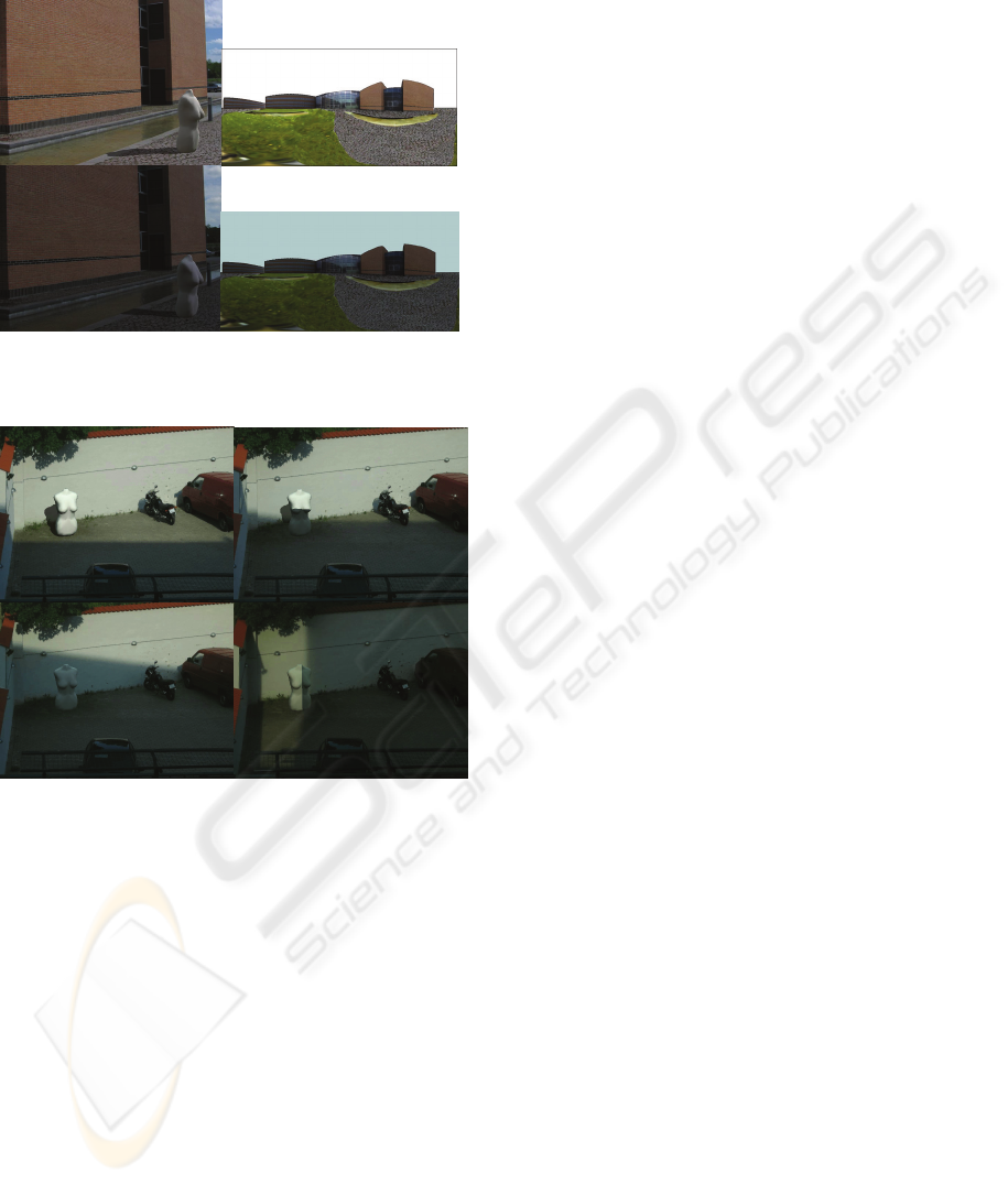
Figure 1: (Left) Virtual object augmented into a scene, calibrated to fit lighting of scene. (Middle) Scene-lighting changes,
virtual object keeps previous shading, and stands out. (Right) Lighting of object is dynamically updated to fit the lighting
of the rest of the scene.
364
Jensen T., S. Andersen M. and B. Madsen C. (2006).
REAL-TIME IMAGE BASED LIGHTING FOR OUTDOOR AUGMENTED REALITY UNDER DYNAMICALLY CHANGING ILLUMINATION CONDITIONS.
In Proceedings of the First International Conference on Computer Graphics Theory and Applications, pages 364-371
DOI: 10.5220/0001353703640371
Copyright
c
SciTePress

to augment virtual objects into a real outdoor scene
and shade the object according to how the system
estimates the lighting of the scene.
To augment virtual objects into a scene and
update the virtual lighting according to the real light
changes, is a dual task; a light estimation is needed,
as well as a rendering pipeline able to update the
lighting of the virtual objects when needed.
This paper focuses on the rendering pipeline of
the system, and briefly describes the light estimation
used in the system.
The outline of the paper is as follows: Section 2
will describe existing state of the art work, and
conclude which progresses may be needed in the
field of Augmented Reality. After that, there will be
a brief description of how the suggested system
estimates the lighting of a given scene, and
represents this knowledge. The rest of the paper
describes the rendering pipeline of the system,
starting with a minimum rendering pipeline using
local illumination, after which the pipeline is
extended to encompass Global Illumination by the
use of Image Based Lighting. The paper is
concluded by a presentation of the results and a
discussion.
2 STATE-OF-THE-ART
Estimating scene illumination from images is the
dual problem of estimating surface reflectance
properties, because the image represents light
reflected off surfaces, and this reflection is governed
by the illumination and the reflectances. Therefore
illumination estimation cannot be performed without
knowledge of surface reflectance. This is the reason
all related work is based on placing some kind of
special purpose object with a priori known
reflectance properties in the scene. For continuously
operating AR or vision systems performing
illumination estimation it is not a viable approach to
be forced to have calibration objects in the scene.
Therefore we have developed and tested a new
approach to estimating dynamic illumination
conditions based on the surfaces naturally present in
the scene. Subsequently we briefly describe some of
the most closely related work.
(Sato et al., 1999) suggested how the illumination
distribution of a scene could be estimated from
analysing shadows cast by a known calibration
object onto a known surface, and rendering virtual
objects into the image using the estimated
parameters for the shading and shadowing.
Furthermore (Debevec, 1998) presented a
method for measuring scene radiances as a High
Dynamic Range Image (HDRI) and adding virtual
objects to a scene with correct lighting, using the
HDRI environment map.
(Gibson et al, 2003) created an algorithm for fast
shadow generation based on an HDRI environment,
and a geometric model of the scene. The result was
subjectively similar to what can be obtained using
offline raytracers, but the system was not created to
be able to estimate and change the lighting in the
scene as lighting conditions changed.
(Kanbara et al, 2004) designed an approach to
automatic, real-time estimation of scene lighting for
augmented reality. The approach involves placing a
reflective sphere which is always in the camera’s
field of view. The dynamic scene illumination
conditions are estimated from the environment’s
reflection in this special purpose sphere.
As seen from the above review, the standard
approaches to determine the illumination conditions
of a scene are to either have a light probe in the
scene, or a calibration object, that both has to be
added to the scene, if the light estimation is to be
updateable.
The goal of this project has been to investigate
whether images of the surfaces naturally present in a
scene can be used for estimating illumination, that is
to detect and estimate dynamic light changes –
without the use of a light probe or a calibration
object – and applying these illumination changes to
an updated shading of a virtual augmented object.
3 RENDERING
As mentioned in the introduction, the task of
augmenting virtual objects into a real scene taking
light changes into account is a dual task. It requires a
light estimation, and a rendering pipeline, that uses
the estimation to illuminate the augmented objects.
The rendering pipeline of the system is the focus
of this paper, while the light estimation is described
in detail in (Jensen and Andersen, 2005). A brief
description of the Illumination Estimation method
Figure 2: Two images taken at different times
(approximately one hour apart) on a sunny day with
partial cloud cover causing constant changes in the
illumination conditions.
REAL-TIME IMAGE BASED LIGHTING FOR OUTDOOR AUGMENTED REALITY UNDER DYNAMICALLY
CHANGING ILLUMINATION CONDITIONS
365

used in the system will be made in the subsequent
section:
3.1 Illumination Estimation
The Illumination Estimation method used to
determine how the light of a certain scene is
configured has a number of constraints and
assumptions that will be listed here. These
assumptions apply to the entire Augmented Reality
system.
The system is only useable outdoor during
daytime. This is due to the assumption that the sun is
the only major light source in an outdoor scene, and
therefore the only direct light source needing
estimation, where the sky is providing secondary
lighting, which will be estimated as ambient light.
The system is constrained to only running under
conditions with no precipitation, as it will alter the
reflectance properties of the surfaces in the scene.
Furthermore the scene that is to be augmented
must contain diffuse surfaces, as these will be the
sources to estimation of the scene lighting.
In order for the system to have the ability to
estimate the light of the scene, a 3D model of the
scene is also required, as well as an HDRI
environment map recorded in the centre of the scene.
Finally, as the light is estimated from the images
recorded by a camera of the scene, the camera needs
to be calibrated to fit the scene. The 3D model of the
environment required in this system, needs only to
be a simple representation, containing only the main
surfaces of the scene. E.g. a square building needs
only representation as a box.
In calibration of the system to the scene, the user
is prompted to mark on an environment map of the
scene, which visible surfaces are considered diffuse,
and can be used for estimation.
When the system has been calibrated, the
Illumination Estimation is able to analyse the images
of the scene taken by the camera, and determine
from the 3D model, the environment map, and a sun
model the intensity of the direct light from the sun,
as well as the intensity of the indirect lighting from
the reflected surfaces in the scene.
The result of the estimation is passed on to the
rendering pipeline as RGB intensities for direct and
ambient lighting and as a light vector giving the
direction vector to the sun. The light parameters are
compliant to the Phong shading model, as a variety
of this model is used to derive the light estimated
parameters.
The Illumination Estimation analyses the images
using 500 randomly selected pixel samples, from
which the light parameters of the used model is
estimated. Under the assumption that a sun model
provides the direction vector to the sun, the method
is able to estimate the light intensity of both direct
and indirect light in the scene, if the camera has
surfaces in both light and shadow within its frame.
E.g. the method will estimate the RGB intensity of
the sun to almost zero, when there is a heavy cloud
cover, because it sees no noticeable difference
between the area in direct light, and the area, that
should be in shadow.
The light parameters are estimated for every
frame in the current implementation of the system,
and runs at 10 fps.
The estimation of light and shading of the virtual
objects is furthermore based on the assumption, that
the sunlight in an outdoor scene is purely directional.
This is not completely correct in reality, but the
angle difference to the incoming sunlight at two
points in a scene that are e.g. 100 metres apart are
insignificant and therefore the system uses the light
direction given by the light estimation in the entire
scene, which also helps speeding up all shading and
shadowing calculations performed real-time.
Another assumption of the project has been that
outdoor environments with brick buildings and tiled
stones are close to being diffuse, which is used to
derive the illumination parameters.
3.2 Basic Rendering
This section describes how a virtual object is
augmented into one frame when the local light
parameters are known.
When the lighting of the given scene has been
estimated, this is used to place an object in the scene
that is subjectively appearing as if it is part of the
scene, instead of an object manipulated into the
frame.
The simplest way to do this is by placing the
virtual object within the scene. Use the Phong
shading model, supported by any 3D hardware, in
conjunction with the estimated light parameters on
the object. This will result in a virtual augmented
object, which seemingly matches the lighting of the
surrounding scene. Except the surfaces of the object
not in direct sunlight will have a constant colour
addition from the surroundings.
To maintain the illusion that the virtual object is
an integral part of the real scene, shadows play as
big a role as the shading itself. Real objects must
cast shadows onto the virtual object; the virtual
object must cast shadows onto the real environment.
To cast shadows from the virtual objects onto the
real environment and vice versa, the Shadow
Volume algorithm is used.
The Shadow Volume algorithm (Crow, 1977) has
been modified to use two sets of shadows; Virtual
GRAPP 2006 - COMPUTER GRAPHICS THEORY AND APPLICATIONS
366
object, and real object shadows, that both have to act
differently in the scene.
Virtual objects must cast shadow on the
environment, but only where a shadow of a real
scene object is not already present.
Real objects must only cast shadows upon the
virtual objects, but not on the real environment,
where nature has already provided a shadow.
Shadow Volumes are extrusions of the object that
is to cast a shadow, in the direction away from the
light source the object is blocking.
Through clever use of the stencil buffer present in
any standard 3D hardware today, the Shadow
Volumes are used to create shadow effects in
multiple passes, where the Volume is intersecting
other fragments.
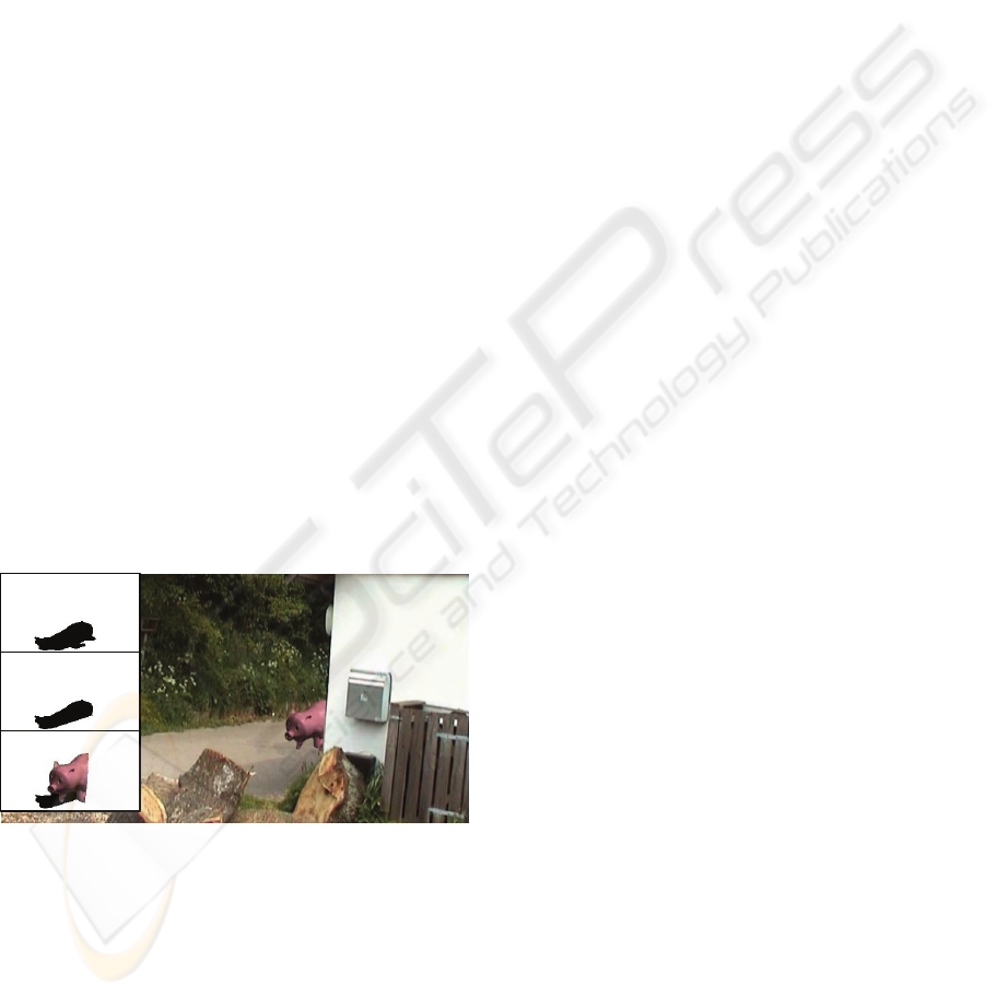
The procedure for this shadow algorithm is
illustrated in Figure 3, where a virtual object is
inserted into a real environment.
The pseudo code for an operation like the one
seen in the figure would look like:
1: Create the shadow for the virtual object
2: Subtract the real objects’ shadow from the virtual.
3: Superimpose on real image.
4: Render virtual objects receiving shadows.
Step 1 is the normal 2-pass Shadow Volume
algorithm, while step 2 is the same procedure only
with the 3D models of the real objects in the scene,
and the buffer decrementing instead of incrementing.
When these two steps are completed, the shadow
interaction onto the surroundings is completed.
In step 3 the virtual shadows are rendered to the
frame where the areas that were determined to be in
shadow are darkened by the relation between the
ambient light and direct light. This approach will not
make a perfect dampening of the shadowed area. A
perfect dampening would require taking the normal
of the surfaces that are to be dampened into account,
which would require more processing per frame.
This has not been implemented in the system.
The final step in the rendering of a single frame
is to render the virtual object into the real image,
with the ambient light on the surfaces that are
occluded from the light source, and direct light
added to the surfaces that are in direct light. Scene
occlusions would here be handled by the depth
buffer.
This procedure would in theory be enough to
represent augmented objects with light being
updated for every frame. The rendering would also
be fast, as both Phong shading as well as Shadow
Volumes can both be hardware-accelerated. The
drawback is that the Phong shading can not create
realistic shading that will allow virtual objects to
actually look as if they are part of a real scene, being
illuminated by the multiple reflections in the scene,
even though an outdoor scene can be considered as a
local illumination environment.
To create more realistic shading, the ambient
part of the Phong shading must be replaced with a
shading method that takes the light reflections in the
environment into account.
3.3 Enhanced Rendering
In the field of Image Based Lighting a common
approach to getting a realistic shading of virtual
objects based on the lighting of the surroundings is
to have an HDRI mapping of the environment.
If this approach is extended to the rendering of
the augmented objects in a real scene, it would mean
that a new map of the environment would have to be
available every time the lighting of the environment
changes. Let us assume, for now, that for every
frame being rendered, there is an environment map
of the surroundings available, that shows the
environment under the current illumination
condition, but without the sun visible in the map.
Such an environment map would represent the
light reflected off the various surfaces in the scene,
plus the sky. In effect it would represent the ambient
light.
Normally when using Image Based Lighting the
surrounding environment is assumed to be far away,
so that the shading is the same in all positioning of
the virtual object. In an Augmented Reality system,
the virtual objects are often very close to the
environment, and therefore this limitation must be
handled.
One way to do this is to use an Irradiance Volume
(Greger, 1998). The Irradiance Volume is a global
illumination approximation, which analyses a given
scene that has already been shaded by any given
shading method. The scene is sampled in various
key points forming a grid throughout all moveable
positions in the scene and the lighting condition in
Figure 3: A virtual pig is augmented into a scene, to create
the shadow effect, the shadow of the surroundings are
subtracted from the pig’s and blended into the image.
Furthermore the surroundings cast shadow on the pig.
REAL-TIME IMAGE BASED LIGHTING FOR OUTDOOR AUGMENTED REALITY UNDER DYNAMICALLY
CHANGING ILLUMINATION CONDITIONS
367

each point is approximated, by finding a low
resolution radiance environment map in each point,
and calculating their corresponding irradiance
environment map.
In order to shade an object in this scene, a lookup
is performed in the Irradiance Volume, where each
vertex in the object is shaded from an interpolation
between the nearest key points in the Irradiance
Volume Grid.
In order to use an Irradiance Volume to shade
augmented objects in the system described in this
paper, it must be modified to use an environment
map instead of a normal renderer, and it must be
able to update the shading every time a new
environment map is available, which in theory could
be for every frame. This means that for every frame
all key points in the volume should be recalculated.
To make sure the system is capable of updating
an Irradiance Volume, pre-processing is required.
In this offline process an environment map of the
entire scene is mapped onto a virtual model of the
scene. When the mapping is completed, an
Irradiance Volume is constructed within the scene,
and it determines how the environment looks from
each key point, storing which pixels of the
environment map are used in which key point, for
use later when the lighting of the scene is updated.
The contents of the environment map will not be
available until execution time.
Furthermore a pre-calculation to accelerate the
transformation of each key point radiance sample
into a irradiance sample is done in the offline
processing, again to use in the online processing
when the lighting of the virtual objects are to be
changed.
The system is made for an outdoor environment,
and the assumption is made that during daylight
outdoor, there is only one major light source, and
everything else is secondary light, which includes
the light from the sky. The Irradiance Volume must
only handle the secondary light, while the Phong
shading handles the direct light.
For this to work the sunlight must be removed
from the environment map used in the volume. How
this is achieved will be described later.
The reasons for having the Irradiance Volume
handle only the secondary light of the scene, is that
it allows self-shadowing of the virtual objects in the
real scene, as well as it ensures that objects in the
real scene can cast a shadow onto the virtual object.
Furthermore the key point samples are in a very
low resolution, which is not optimal when there are
major light sources in the scene that the Irradiance
Volume must handle. Though with ambient light, it
is not as critical.
3.4 Runtime Rendering
When the system starts up, the scene is analysed and
the Illumination Estimation delivers a set of Local
Illumination parameters describing the light of the
scene.
The result of the processing of the light
parameters is an environment map of the scene,
updated to match the current lighting.
When the shading algorithm has obtained an
environment map from the Illumination Estimation,
the contents of the environment map is redirected to
the key point samples in the Irradiance Volume.
In the offline process it was calculated which how
the different pixels in the environment map
translated into the various key points. This pre-
calculation is now used to fast update the key point
samples that are needed in order to shade the virtual
objects in the scene.
When the samples have been updated, the
Ambient Irradiance Volume can shade virtual
objects with what can be described as sunlight
reflected from the environment.
To fully make the shading realistic, the sunlight
must of course be taken into account as well, which
is where the normal Phong renderer is used, all
being finished off with the Shadow Volume making
sure the shadow interaction between the real and
virtual object is correct.
This is basically the rendering of one frame,
where the lighting and shadowing are handled by
Phong, Irradiance Volume, and Shadow Volume
respectively.
4 UPDATING ENVIRONMENT
MAPS FOR SHADING
As previously mentioned, the shading of the virtual
objects is achieved with the use of Image Based
Lighting, where an environment radiance map is
filtered into its correspondent irradiance map.
In the system suggested in this paper, the process
of converting an environment map to an irradiance
map is done real-time, as the system is generating a
new environment radiance map every time the
lighting in the scene is estimated to differ from the
last known light parameters.
This section describes how an environment map
is created at runtime, which represents the current
light of the scene.
To employ the use of Image Based Lighting in a
system, that needs to update the shading of the
virtual objects whenever needed, one needs to be
GRAPP 2006 - COMPUTER GRAPHICS THEORY AND APPLICATIONS
368
able to update the images the lighting is based upon,
namely the environment map.
In order to create these environment maps, and
fast, certain information is required to be known
beforehand, that are collected in an offline process.
4.1 Offline Process
The basic information needed, when attempting to
relight an environment map, is a 3D model of the
scene the environment map represents, and
knowledge of where the environment map is
recorded from. The 3D model of the scene is
already a request from the online rendering, in order
to let the virtual objects interact with the
surroundings in terms of occlusions.
An environment map of the surroundings is also
required. This environment map must be an
“Albedo Environment Map”, describing each
viewable surface’s diffuse reflectance.
The “Albedo Map” can be obtained by mapping
a recorded HDRI environment map onto the 3D
scene model, and perform an inverse rendering of
the scene, whereby the original diffuse reflectance
parameters may be obtained. This off course only
works perfectly if all surfaces in the scene are
diffuse reflectors. While this is naturally not always
the case, we have experimentally verified that brick
walls and pavement can be considered diffuse.
An important aspect when handling lighting is
all light contributions to points in a scene. E.g. a
point in the middle of a field where there is far to
the closest building receives far more light, than a
point close to the building.
If an updated environment map is to be created
from an “Albedo Environment Map”, this aspect
must be taken into account. This is handled by the
“Weighted Ambient Environment Map”, that is an
environment map, that describes how much light
each point receives from the skydome in a scene.
This map can be pre-calculated in either an offline
program, or by a radiosity rendering of the scene
with an all white skydome, (Whitehurst, 2001).
Another environment map that can be generated
offline, and used to speed up the process of creating
new environment maps is a normal environment
map of the scene, (Decaudin, 1996).
The creation of a normal map is based on local
illumination model, where the colour returned from
each point during lighting is a product of the
reflectance of the surface, the power of the light that
affected it, and the angle at which the light affected
the surface. This knowledge may be used in a very
simple way to extract the exact surface normal of
any point visible from the camera. If the geometry
is lighted from the principal directions, only one
component of the surface normal will react to each
principal direction. With this in mind the surface
normal of each point may be derived using only 2
render passes. The render is set up by having a
directional lighting from each principal direction
with one colour channel for each direction. In the
first render only the positive surfaces are lighted,
while the negative surfaces are lighted in the second
render. The surface normal of each point in the
scene is now obtained by subtracting the negative
image from the positive image, and each colour
component now corresponds exactly to the normal
components of each points.
To sum up the offline process, the following
information needs to be gathered:
• 3D model of the scene.
• HDRI environment map of the scene
From which the following information can be
obtained:
• Albedo environment map
• Weighted Ambient environment map
• Normal environment map
4.2 Online Processing
When all necessary offline information has been
gathered, the system is able to create environment
maps for the scene as requested from changing light
conditions in the scene.
The creation of Environment Maps is based on
the Phong local illumination model, with certain
modifications described in the following sections.
As earlier mentioned, the shading and shadowing
of the virtual objects is based partly on the
assumption that the light from the sun, which is
assumed to be the only major source of light in the
scene, is directional.
This assumption can be reused in the rendering
of new Environment Maps. If the light in a scene is
directional, the vector to the light is the same for all
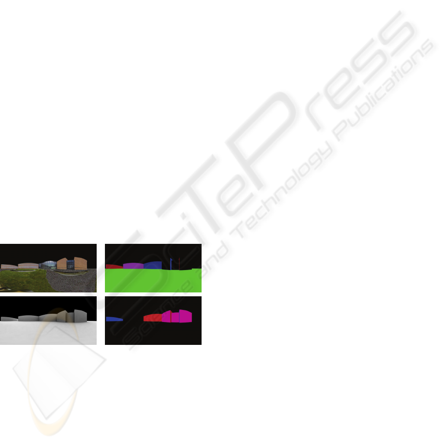
Figure 4: (Top Left): Albedo Environment map. (Bottom
Left): Weighted Ambient Environment map. (Top Right):
N
ormal map displaying the positive components of eac
h
point in the scene. (Bottom Right): Negative Normal map.
REAL-TIME IMAGE BASED LIGHTING FOR OUTDOOR AUGMENTED REALITY UNDER DYNAMICALLY
CHANGING ILLUMINATION CONDITIONS
369
points in the entire scene. This entails that 3D space
coordinates are not needed for any point to calculate
how it is affected by light, all that is required is the
point’s normal vector.
If this knowledge is used when looking at an
environment map, it means that the shading of all
pixels in the environment map can be calculated if
the normal vector of the point represented by that
pixel is known. No 3D rendering is required; it can
all be done with simple pixel operations.
The normal vector of each pixel is given by the
normal map created in the offline process.
When the lighting of each pixel in the
Environment Map is known, it is multiplied by the
Albedo value of each pixel. This is all needed to
obtain a basic re-lighted environment map
representing the current lighting of the scene.
Of course this is not a correct representation, so
an effort is done to remedy this fact. In the offline
process a weighted ambient map was created, that
represents how much skylight is affecting the
various pixels in the environment map. This is to
make sure that vertical surfaces receive less light
than horizontal surfaces, and thereby taking the
skylight effect into the shading of the environment
map. This is used during the relighting to make sure
the various points in the scene receive the right
amount of light from the skydome in the resulting
environment map.
Another important aspect to take into account,
especially if ones virtual object is placed in the
shadow of a real object, is that the shadows cast by
the sun should also be present in the environment
map. Therefore a shadow environment map is
created at runtime that is a binary map, displaying
only if an environment map pixel is either in direct
or indirect light. The Shadow environment map is
created using the shadow volume algorithm used to
create shadow interactions between virtual and real
objects. The shadow environment map is a mapping
of only the areas of the scene that the real
environment casts into shadow. This information is
generated anew every time the Environment map
re-lighting algorithm detects that the light direction
has changed significantly in regards to the lastly
generated shadow environment map.
If this information is taken into account, the
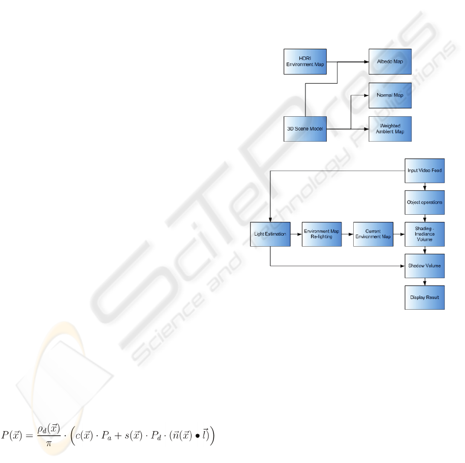
rendering equation for each pixel is:
Where ρ
d
is the the pixels diffuse albedo, c is the
weighted ambient map, s is the binary shadow map,
n is the normal and l is the estimated light direction.
P
a
is the ambient light parameter estimated by the
Illumination Estimation, while P
d
is the direct light
parameter, and P is the pixel intensity in direction x.
This rendering equation is the same used to
estimate the light of the scene, and the output is in
scaled radiance units. The sky is set to the estimated
ambient colour in the environment map.
5 FINAL PIPELINE
The rendering pipeline used in the system presented
in this paper consists of two parts, as seen in the
previous chapters, an offline and an online part.
In the offline part, the maps needed in the online
rendering pipeline are generated using data collected
from the scene that is to be augmented, see figures:
Figure 5: The offline pipeline used in the system.
Figure 6: The online rendering pipeline used in the system.
6 RESULTS
The system described in this article has been tested
using various scenarios, both real and simulated
data. Two of these scenarios are particular
interesting in regards to the rendering pipeline
presented in this paper. Both scenarios show
different aspects of the system.
The first scenario is the situation described in the
introduction, where an object is placed within a
courtyard, and the sun moves during the day, as well
as clouds moving in front of the sun.
The second scenario is a parking space behind a
building, where shadows of real objects interacts
GRAPP 2006 - COMPUTER GRAPHICS THEORY AND APPLICATIONS
370
with the area where the virtual augmented object is
placed. An excerpt of the frames in the two
scenarios can be seen in figures 7 and 8:
Figure 7: Two rendered images, and their corresponding
generated environment maps used for the ambient shading
of the virtual object.
Figure 8: A scene displaying the systems ability to interact
with the shadows of the environment. Furthermore it
shows the ability to adapt the lighting to correspond to the
surroundings, as well as displaying the necessity for a
global illumination approximation for the ambient part of
the shading, when the object is positioned in shadow.
Tests have shown that the system is capable of
running at 10 fps when relighting every frame. The
testing was performed on a 1.53 GHz AthlonXP
processor with a GeForce3 graphics adapter, which
by today’s standards is a relative slow machine so it
is presumable that the system may run up to 25 fps
on newer hardware.
Furthermore the implemented system is by no
means fully optimized, so further performance may
be obtained from an optimization. One such
optimization could be to bypass the relighting of
environment maps, and relight the key point samples
instead, in the vicinity of where the shaded object is
positioned, which likely will demand less workload
per frame.
Videos of the two featured scenes can be seen at:
http://www.control.auc.dk/~toje01-nobackup
7 DISCUSSION
The method presented in this paper enables an
augmented reality system to create a realistic
lighting of virtual objects in outdoor environments
where predictable and unpredictable light changes
occur.
The shading is based on estimated local illumination
parameters, which are converted into an
environment map representing the newest light
changes in the scene. This gives the system the
ability to update the image based lighting of a virtual
augmented object real-time.
REFERENCES
Sato, I., Sato, Y., and Ikeuchi, K., 1999. Illumination
distribution from shadows. In Proceedings: CVPR99.
Debevec, P., 1998. Rendering synthetic objects into real
scenes: Bridging traditional image-based graphics
with global illumination and high dynamic range
photography. In Proceedings: SIGGRAPH 1998.
Gibson S., Cook, J., Howard, T., and Hubbold, R., 2003.
Rapid shadow generation in real-world lighting
environments. In Proceedings: EuroGraphics
Symposium on Rendering.
Greger, G., Shirley, P., Hubbard, P. M., and Greenberg, D.
P., 1998. The irradiance volume. IEEE Computer
Graphics and Applications.
Whitehurst, A., 2001. Depth map based ambient occlusion
lighting.
http://www.andrew-whitehurst.net/amb_occlude.html.
Decaudin, P., 1996. Cartoon looking rendering of 3D
scenes. Research Report 2919, INRIA.
Jensen, T., and Andersen M., 2005. M. Sc. Thesis:
Estimating and Applying Dynamic Light Changes to
Environment Maps in Real-time for use in Image
Based Lighting. Aalborg University.
Crow, F.C., 1977. Shadow Algorithms for Computer
Graphics. SIGGRAPH ’77 Proceedings.
Kanbara, M., and Yokoya, N., 2004. Real-time estimation
of light source environment for photorealistic
augmented reality. In Proceedings of the 17th
International Conference on Pattern Recognition.
REAL-TIME IMAGE BASED LIGHTING FOR OUTDOOR AUGMENTED REALITY UNDER DYNAMICALLY
CHANGING ILLUMINATION CONDITIONS
371
