
DISTRIBUTED CONTROL SYSTEM OF AN EXPERIMENTAL
ROBOTIC CELL WITH 3D VISION
Andrés S. Vázquez, Antonio Adán, Roberto Torres, Carlos Cerrada*
Escuela Superior de Informática, UCLM, Paseo de la Universidad 4, Ciudad Real, Spain
*Escuela Técnica Superior de Ingenieros Industriales, UNED. Madrid, Spain
Keywords: Distributed Robot Control, Vision 3D, Industrial Robots, Manufacturing environments.
Abstract: We present a distributed control architecture for the integration of an experimental robotic cell with 3D
visual servoing. This architecture allows us to control a 6 DOF robot in hard Real-Time and the global
experimental system in soft Real-Time. We have developed distributed applications, based on this
architecture, for the robot control (whose characteristics permit us to teleoperate the robot), the 3D data
acquisition and for an advanced simulation and visualization. These applications, together with the
algorithms developed by our computer vision research group, allow a full intelligent robotic manipulation in
complex scenes to be made. This can be useful in manufacturing environments where an automated piece
manipulation is necessary.
1 INTRODUCTION
The distributed control of industrial processes is
linked to the communication systems. The elements
of a plant or process will determine the control
action and the integration architecture. This
architecture is abstracted in different levels of
integration and production following the Computer
Integrated Manufacturing (CIM) philosophy.
Experimental systems based on robotic visual
servoing need the development of special distributed
architecture for its integration. Moreover, like in any
robot system, the interaction with the world imposes
a real time constraint on computing.
The requirements for a distributed robot
architecture have been studied for many years. A
reference for these kinds of architectures was given
by NASA in (Albus et al., 1989). There are many
research works in distributed robot control, above all
in mobile robotics. For example in (Woo et al.,
2003) a distributed mobile robot software
application infrastructure is developed. In industrial
robots the research is focused on robot integration in
networked manufacturing and in any kind of
teleoperation. One example of distributed control for
manufacturing can be found in (Pires et al., 2001)
and an example of distributed control architecture
for teleoperation can be found in (Fung et al., 2002).
The 3D vision servoing has been used in robotic
research environments for many years. These
techniques are used in mobile robots for navigation
and recognition tasks. For example in (Mallet et al.
2000) the authors use a stereo system to estimate the
position of a mobile robot in outdoor environments.
In industrial robots the 3D vision techniques are
used for robot control, inspection/recognition and
manipulation. For example, in (Saedan et al. 2001),
3D techniques are used to determine the position of
a manipulator robot.
In this paper we present the integration of the
distributed components of an experimental robotic
cell based on 3D visual servoing. In order to carry
out this integration it has been necessary to develop
a software architecture, which allows us to
implement a hard Real-Time control of a 6 DOF
manipulator robot and a robust and reliable
communication of the global cell with soft Real-
Time specifications.
2 EXPERIMENTAL ROBOTIC
CELL
During the last years, our Computer Vision research
group has focused on developing 3D vision
techniques. In order to test these 3D techniques we
508
S. Vázquez A., Adán A., Torres R. and Cerrada C. (2006).
DISTRIBUTED CONTROL SYSTEM OF AN EXPERIMENTAL ROBOTIC CELL WITH 3D VISION.
In Proceedings of the Third International Conference on Informatics in Control, Automation and Robotics, pages 508-511
DOI: 10.5220/0001210305080511
Copyright
c
SciTePress
have an experimental robotic cell based on a 6-DOF
manipulator robot with 3D visual servoing. A
system control based on our 3D techniques allows
the cell to be used as an intelligent element of
manipulation with many applications in
manufacturing environments. For example, it would
be useful in quality control processes, classification
or manipulation of pieces, assembly tasks, etc.
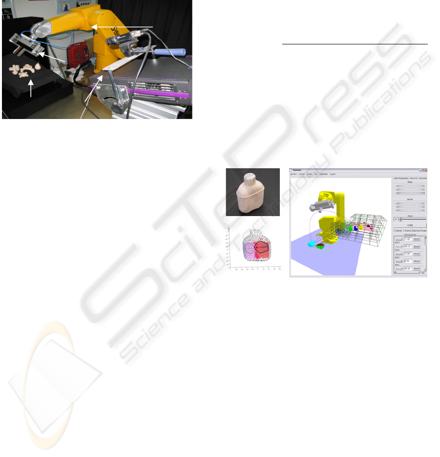
Figure 1: Experimental Cell.
2.1 Software Systems
To allow the robot to interact with a complex scene,
it has been necessary to develop the following
applications and tools:
Segmentation Tool. The algorithm presented
in (Merchan et al., 2002) obtains the segmented
elements of complex scenes with occlusions,
shadows, etc, and its distribution around the scene.
Recognition Tool. The segmented objects are
recognized through the algorithm presented in (Adán
et al. 2006). As a result, the recognition as well as
the pose of the object is given.
Grasping Tool. The grasping algorithm
presented in (Adán et al. 2005) works on the 3D
complete model given by the recognition algorithm.
Figure 2.a shows the image of a real object. The
grasping point in the 3D modelled object is shown
in Figure 2.b.
Path Planning Tool. Our algorithm of path
planning (Vázquez et al., 2006) is a new sample-
based algorithm suitable for dynamic environments.
Figure 2.c shows an example of the trajectory
generated by our path planning algorithm.
Control Robot Application. Application based
on the distributed architecture of Section 3 for the
remote control of the robot with Real-Time
specifications. This hard Real-Time control together
with the soft Real-Time control of the global
experimental cell allow us to schedule a parallel
control in order to improve the reliability, security
and speed of the system.
Remote 3D Acquisition Application. Server
application based on Corba which allows us to
control the Range Sensor in order to acquire 3D data
remotely.
Advanced Simulation Application. 3D
dynamic simulator of robots with the following
characteristics:
- Multi-platform (Windows, Linux).
- Generic robot simulation based on CAD
models (robot morphology) and ROBOOP
libraries [http://www.cours.polymtl.ca/roboop/
]
(kinematics solution).
- Simulation of dynamic environments with
ODE (Open Dynamics Engine) based on 3D
synthetic models (CAD) or 3D real model (from
the 3D sensor). Also it is used as a collision
detector.
- The architecture discussed in Section 3 makes it
possible to be use as a visualization tool
(teleoperation) or as a feedback tool (3D data
repository, collision detector, etc).
(a)
(b)
(c)
Figure 2: a) Real Object. b) Grasping point of an object.
c) Path planning Trajectory (into the simulator).
3 CONTROL ARCHITECTURE
As we have seen, the experimental cell is composed
of different systems, which implies we need a
distributed system to integrate all the elements.
Moreover, the use of a robot implies having to add
characteristic of Real-Time to the distributed system.
In fact, the integration of our experimental robotic
cell in manufacturing environments implies the
following requirements:
- Hard Real-Time control of the robot.
- Soft Real-Time control of the global system for
quality of service (QoS) in communications and
reliable executions of tasks.
Rx90
Robot
Parallel
Gripper
3D Sensor
Complex
Scene
DISTRIBUTED CONTROL SYSTEM OF AN EXPERIMENTAL ROBOTIC CELL WITH 3D VISION
509
Remote Robot
Controlle r
(PC)
RTCorba Interface
Real Time
Communica tion
Tas k
Local Ro bot
Controlle r
(CS8)
3D Data
Acquisition
Server
RTCorba Interface
Robot
Simulator
(client/server)
RTCorba Interface
RTLin ux SolarisVxWorks Windows Linu x
3D Data
Acquisition
GUI (client)
RTCorba Interface
Windows Linu x
3D Pro cessing
Tools
RTCorba Interface
Windows
Graspi ng
Pla nne r
RTCorba Interface
Windows
Pat h
Pla nne r
RTCorba Interface
Windows
Manual Motion
GUI (client)
RTCorba Interface
Windows Linu x
Rx90-robot
Range Se nsor
RS232 BUS
Real-Time Corba ORB (TAO)
Control Software
Hardware
Software Tools
Software Applications
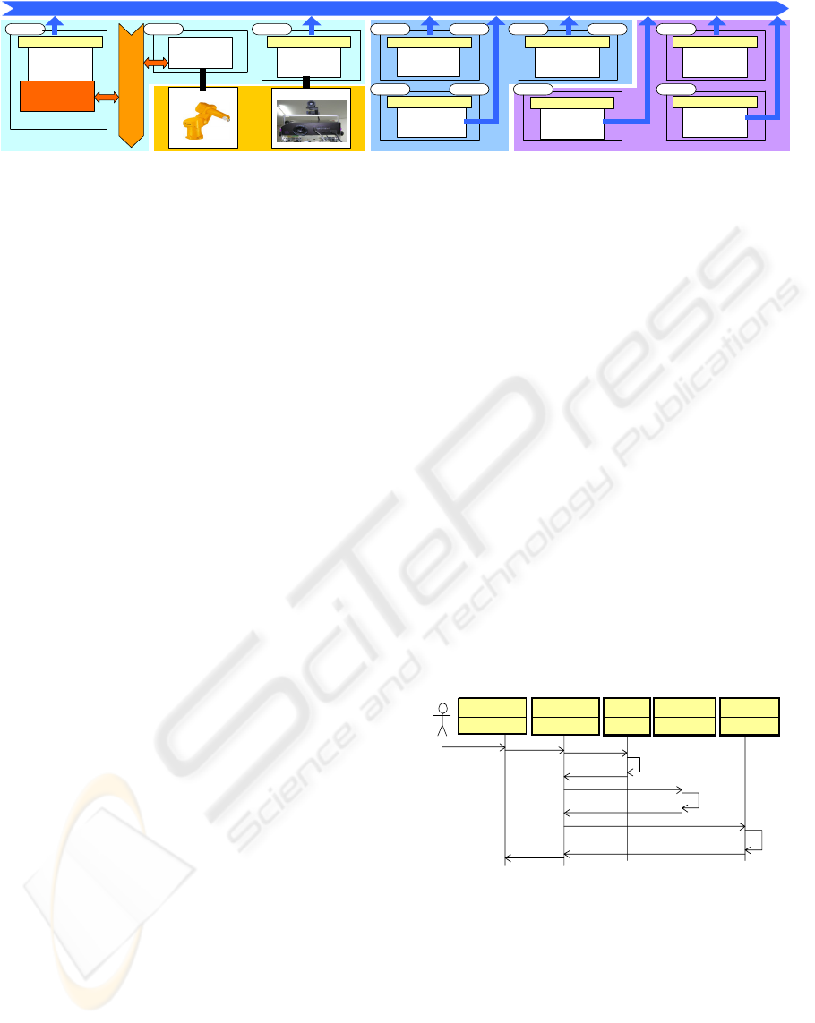
Figure 3: Distributed architecture for the global experimental system.
3.1 Real-Time Robot Control
The CS8 robot controller permits Real-Time task
execution. In order to do a remote control it is
possible to establish a communication between the
controller and a PC via RS232 serial port. This port
is an asynchronous canal which means that it
presents a problem of Real-Time scheduling.
In the CS8 controller side, the communication
task can have the maximum priority in order to
avoid exclusion problems. In this way it is possible
to send/receive data in a t period.
The serial data in a PC will be read in a variable
t’ time. We use RTLinux for converting the
communication into a Real-Time process. In this
way t’ can be fixed. Ideally t and t’ should be equals,
but this has many inconveniences: It needs to
synchronize clocks and it will not be robust in
presence of errors. For example t and t’ could
change due to communication errors, loss of priority
by O.S. exceptions, etc. We propose instead:
- Using a non Real-Time task which reads the
serial port and writes in a RTFIFO. In this way,
another Real-Time task can read data from the
RTFIFO with a t’ period. Therefore, if t’>t the
correct data is read. If t’<t there are two ways: Take
the last data (but it could be old) or make an
interpolation between the n last data.
Moreover, using RTLinux will allow us to have
faster controllers due to the improvement of the
system clock granularity (which also means
parallelism improvement).
3.2 Distributed Cell in Soft Real-Time
Our system is a heterogeneous environment with
different operating systems, languages and
communication ways. Those systems without
“critical” actions in the robot, such as the 3D data
acquisition subsystem, can assume Soft Real-Time
specifications. Between the different technologies
for distributed systems in heterogeneous
environments we have chosen TAO Real-Time
Corba specification. TAO allow us to optimize the
communication and turn our system into a soft Real-
Time system. Therefore the elements of our system
are encapsulated in distributed objects. The resulting
architecture is shown in Figure 3.
TAO's Real-Time Scheduling Service supports
static rate monotonic scheduling and dynamic
maximum urgency first scheduling (using the Real-
Time event service) to assign priorities and validate
schedulability. We have chosen the dynamic
maximum urgency first scheduling, because tasks of
maximum urgency can appear in our system (for
example an emergency stop). Moreover, tasks like
the collision detecting module need high priority,
that is why the processes need to be scheduled.
3.2.1 Objects Interaction
The following grasping process is an example of
how objects interact with each other. This process
can be divided into the following parts:
a) 3D data processes. The diagram of Figure 4
shows how the user obtains the 3D data of the
complex scene of objects by the simulator.
: Cell Simulator: Cell Simulator :Se gme nta t io n:Se gme nta t io n :Recognition:Recognition:3 DS er ve r:3 DS er ve r: 3 D Rep os itor y: 3 D Rep os itor y
Scene A cqu isitio n
3d Acq uis ition
Process
Rang e I mag e
Scene Segmentation
Segmentation
Algorithm
Segmented Objects
Object Recog nitio n
Recognition
Algorithm
Recognized and Positioned Objects
3D modeled
Objects
Show World
Scene request
Figure 4: Sequence diagram for the 3D data processes.
b) Planning processes. The user is able to select an
object to grasp after the 3D data has been processed.
Figure 5 shows the process of planning a grasp. As a
result of these processes, the remote control will
know the sequence of the robot configurations
(trajectory) to carry out the grasping.
c) Robot execution processes. Every movement is
tested in the virtual world before being executed in
the real robot (to check collision and so on). This
process can be serial or parallel.
ICINCO 2006 - ROBOTICS AND AUTOMATION
510
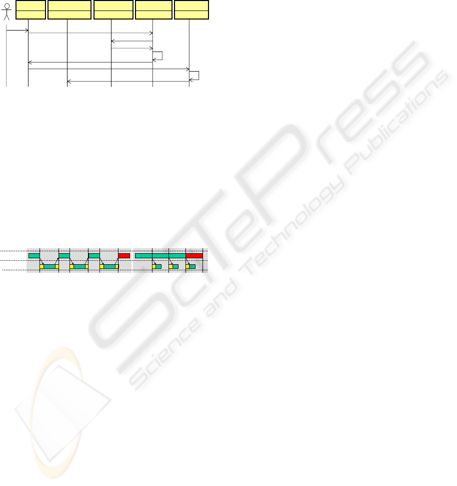
In the serial process (Figure 6.a) there is an
accumulated delay in every movement due to the
computational time (in the simulation) and the
communication time. This sequence is suitable just
for process where the speed in not important, but not
for critical process such as teleoperation where it is
necessary to optimize the performance.
: S imu lato r: S imu la to r :Robot Contro lle r:Robot Controller :Grasp P lanner:Grasp P lanner:3 D Rep os it or y:3 D Rep os it or y
Ob je c t Se lect in g
Gras p an Object
Trajectory Request
Trajectory
Gras ping
Algorithm
:Path Planner:Path Planner
3D Object Request
3D Ob ject Model
Gra s p P o in ts
Path planning
Algorithm
Figure 5: Sequence diagram for the planning processes.
Parallel process is carried out by a global
Scheduler with a Real-Time manager, which
controls both virtual and real movement
guaranteeing a security delay. The computational
time of a movement in the simulator will depend on
the complexity of the virtual world. The hard Real-
Time control of the robot seen in section 3.1 allows
the Scheduler to know the state of the real
movement and to modify the speed of this
movement (even to stop it by a emergency stop task
with the highest priority) in order to guarantee the
security delay in each movement.
1
1
Virtual
Movements
Real
Movements
2
2
3
3
4 1 2 3 4
1 2 3
Figure 6: a) Serial processes b) Parallel processes.
The scheduler is designed through the analysis of
the robot in Real-Time and the analysis of the
computational and communication parameters. In
our case, Real-Time Corba gives the necessary
quality of services to the communication parameters
to allow our system to be scheduled as is seen in
section 3.2. Figure 6.b shows a sequence example in
which the virtual movements are slower than real
movements, that is why the process is scheduled
with a security delay equivalent to the time of one
virtual movement plus the communication.
4 CONCLUSIONS
In this work we have presented the integration of an
experimental robotic cell with 3D servoing for
manipulation environments. We have developed a
distributed architecture based on Real-Time Corba
using the ORB supplied by TAO. This architecture
together with the hard Real-Time control of the
robot, based on RTLinux, allows us to turn the
global system into a soft Real-Time system in order
to improve its security, reliability and speed.
Distributed applications have been developed
following this architecture, such as the advanced
simulator, the 3D acquisition application and the
robot control application.
After this integration, the experimental cell can
work for full intelligent manipulation environments
as well as a secure robot teleoperation.
ACKNOWLEDGEMENTS
This research has been supported by the CICYT
Spanish projects PDI2002-03999-C02 and
DPI2005_03769.
REFERENCES
Albus, J.S., McCain, H.G., Lumia, R., NASA/NBS
Standard Reference Model for Telerobot Control
System Architecture, NIST, Technical Report 1235,
Gaithersburg, MD, April 1989.
Woo E., MacDonald B. A.., Trépanier F.. Distributed
mobile robot application infrastructure. IROS’03,
pages 1475-80, Las Vegas, October 2003
Pires, JN., Monteiro, P., Schölzke, V., Using Robot
Manipulators on High Efficient Wrapping Machines
for Paper Industry, ISR’2001, Seoul, Korea, 2001
Fung W. K., Xi N., Lo W. T., Liu Y. H., Improving
efficiency of Internet based teleoperation using
network QoS, ICRA 2002
Mallet, A., Lacroix, S., Gallo, L., Position estimation in
outdoor environments using pixel tracking and
stereovision. ICRA’00, pages 3519, April 2000.
Saedan, M., Ang, M. H, 3D Vision-Based Control of an
Industrial Robot, IASTED International Conference on
Robotics and Applications, Nov 19-22, 2001, Florida,
USA, pp. 152-157.
Merchán, P., Adán, A., Salamanca, S., Cerrada, C., 3D
Complex Scenes Segmentation From a Single Range
Image Using Virtual Exploration, Lecture Notes in
Artificial Intelligence, pp 923-932,. Springer. 2002.
Adán, A., Merchan, P., Salamanca, S., Recognition of
Free-Form Objects in Complex Scenes Using DGI-BS
Models. Submitted to the 3DPTV’06 Chapel Hill,
USA. 2006
Adán, A., Vázquez, A.S., Molina, F., Grasping Solutions
through MWS Models. ICAR’05 ISBN: 0-7803-9178-
0 Seattle (Washington). USA 2005
Vázquez, A. S., Torres, R., Adán, A., Path Planning for
Manipulation Environments through Interpolated
Walks. Technical Report, Grupo ISA, UCLM, Spain.
2006.
DISTRIBUTED CONTROL SYSTEM OF AN EXPERIMENTAL ROBOTIC CELL WITH 3D VISION
511
