
RANGE DETERMINATION FOR MOBILE ROBOTS USING ONE
OMNIDIRECTIONAL CAMERA
Ola Millnert, Toon Goedem
´
e, Tinne Tuytelaars, Luc Van Gool
Katholieke Universiteit Leuven, ESAT-PSI
Kasteelpark Aarenberg 10, B-3001, Heverlee, Belgium
Alexander H
¨
untemann, Marnix Nuttin
Department of Mechanical Engineering, Katholieke Universiteit Leuven
Celestijnenlaan 300B, B-3001, Heverlee, Belgium
Keywords:
Robot navigation, range determination, omnidirectional cameras, obstacle detection.
Abstract:
We propose a method for computing the absolute distances to obstacles using only one omnidirectional camera.
The method is applied to mobile robots. We achieve this without restricting the application to predetermined
translations or the use of artificial markers. In contrast to prior work, our method is able to build absolute scale
3D without the need of a known baseline length, traditionally acquired by an odometer. Instead we use the
ground plane assumption together with the camera system’s height to determine the scale factor.
Using only one omnidirectional camera our method is proven to be cheaper, more informative and more com-
pact than the traditional methods for distance determination, especially when a robot is already equipped with
a camera for e.g. navigation. An additional advantage is that it provides more information since it determines
distances in a 3D space instead of one plane.
The experiments show promising results. The algorithm is indeed capable of determining the distances in
meters to features and obstacles and is able to locate all major obstacles in the scene.
1 INTRODUCTION
In autonomous robot navigation, detection of obsta-
cles is a vital part. Much of the system’s capabilities
boil down to being able to locate obstacles in an effi-
cient and reliable way. Obstacle detection can be car-
ried out in a variety of ways, most commonly using
laser range scanners. Here we propose an alternative
method to locate obstacles in the scene. This novel
approach computes the absolute distances in the scene
using a single omnidirectional camera mounted on the
robot.
The method we propose introduces the following
advantages. Firstly, since cameras, and foremost om-
nidirectional cameras, have emerged as a popular sen-
sor in automatic robot localisation, navigation and
interaction, it is a natural extension to incorporate
the distance determination among the tasks that the
computer vision algorithms carry out. Secondly, our
method is capable of detecting obstacles in almost
the whole sphere surrounding the camera. Compared
with range scanners, who have a field of view of one
half plane, our method provides much more informa-
tion. Thirdly, our approach does not restrict the ap-
plication to any predetermined movements and can
be used in natural environments. Fourthly, camera
based methods usually compute the relative distances,
while the method we propose locate the feature’s ab-
solute position in the scene. Our distance representa-
tion makes the algorithm easier to integrate with other
systems, e.g. path planning and localisation.
The algorithm has been applied to an automatic
wheelchair. The goal of the application is to im-
prove impaired peoples mobility independence. A
path following algorithm has already been devel-
oped, see (Goedem
´
e, 2005), which uses an omnidi-
rectional camera for localisation and map building.
The wheelchair was priorly relying on a laser range
sensor to detect obstacles. The goal of this algorithm
is to replace the laser range scanners, which reduces
costs greatly.
This paper is organised as follows; In section 2 a
short overview of the closest related work is given,
including references to work on omnidirectional cam-
eras. In section 3 a high level overview of the com-
puter vision methods used is given, as well as our
contribution. In section 4 are the experimental results
shown. The paper is concluded with a discussion in
section 5.
366
Kumar S. (2006).
VISUAL SPEECH RECOGNITION USING WAVELET TRANSFORM AND MOMENT BASED FEATURES.
In Proceedings of the Third International Conference on Informatics in Control, Automation and Robotics, pages 366-371
DOI: 10.5220/0001210203660371
Copyright
c
SciTePress
2 RELATED WORK
There are many methods of how to compute range
data in a scene. A classical method is to use range
scanners. Albeit straightforward, this approach has
in the past been limited to 2D-range data. Obstacles
can only be detected if they intersect the horizontal
plane in front of the sensor. Typically, this makes it
difficult to impossible to detect tables. Recently there
have been research to extend the 2D-laser range scan-
ner to 3D. One approach is to rotate or nod a 2D-laser
range scanner (N
¨
uchter, 2005) and in this way obtain
a greater vertical view. The main drawbacks of this
approach are the power consumption and robustness
in moving large objects, the 2D-laser range scanners
are heavy. Another approach proposed by Ryde et
al. in (Ryde, 2006) is to use a 2D-laser range scanner
together with a rotating mirror. This approach is not
feasible for real-time applications since the mirror has
a rotation period of 40 seconds.
There have also been extensive research in range
computation using vision. A survey of different com-
puter vision methods to compute the range informa-
tion is given in (Jarvis, 1983) and an overview of om-
nidirectional cameras and their epipolar geometry is
given in (Svoboda, 1999). In (Zhang, 2002) Zhang
et al. have developed a method to compute relative
range data with one omnidirectional camera. They
use the symmetry in panoramic images as a global
feature. They are then able to solve problems as rel-
ative 2D range estimation and object classification.
Furthermore in (Chahl, 1997) Chahl et al. have pro-
posed a procedure to compute relative range data us-
ing image deformations, which is limited by predeter-
mined translations.
Our work is distinct from these mentioned above
in the important ways that it computes absolute 3D
distances to features in the scene and that it can be
used in a natural environment, no artificial mark-
ers are needed. Even though our approach uses the
ground plane assumption, it does not restrict the robot
to move any predefined lengths. Compared to the 3D-
laser range scanner methods our approach is very easy
to use. It is also very power efficient and cheap using
only one camera and mirror. It is also comparably
fast.
3 ALGORITHM
The goal of the algorithm is to compute the absolute
distances to features in the scene using only one om-
nidirectional camera.
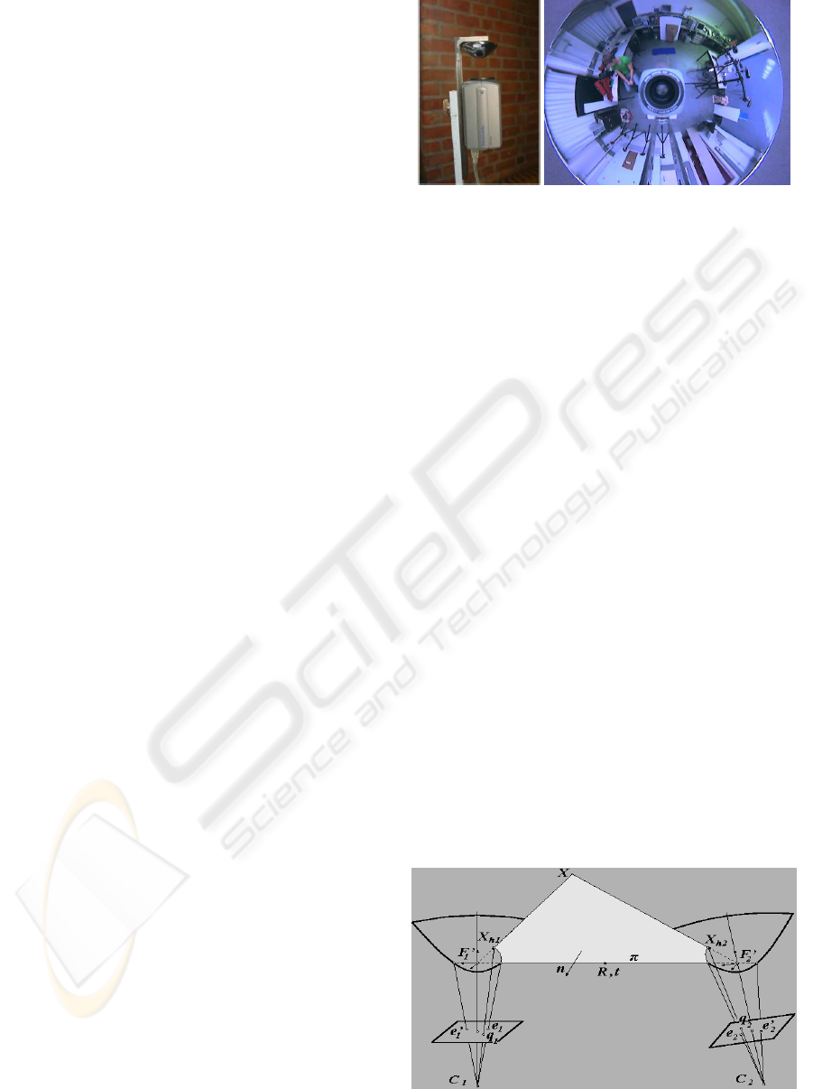
Figure 1: The camera setup and an image from the omnidi-
rectional camera.
3.1 Camera System
It is assumed that the robot system, a wheelchair, is
moving in one horizontal plane.
The omnidirectional view is obtained by mount-
ing an ordinary perspective camera under a hyperbolic
mirror. A hyperbolic mirror has two focal points and
in order to have a central projection camera system
it is crucial that the camera centre coincides with the
second focal point of the mirror, e.g. where the re-
flected rays intersect. This yields a central projection
camera system with, in our case, a field of view of
360
◦
×108
◦
. Figure 1 shows this system and a typi-
cal image acquired by it. The camera system is fully
calibrated. It was calibrated using the ”The omnidi-
rectional Calibration Toolbox Extension” by Christo-
pher Mei which is based on the ”Caltech Calibration
Toolbox” by Jean-Yves Bouget (Mei, 2006).
3.2 Feature Tracking
Correspondences between the views are established
using the popular KLT-tracker of Kanade et al. (Shi,
1994). KLT starts by identifying interest points (cor-
ners), which then are tracked in a series of images.
The basic principle of KLT is that the definition of
corners to be tracked is exactly the one that guaran-
Figure 2: Epipolar geometry for panoramic cameras.
RANGE DETERMINATION FOR MOBILE ROBOTS USING ONE OMNIDIRECTIONAL CAMERA
367
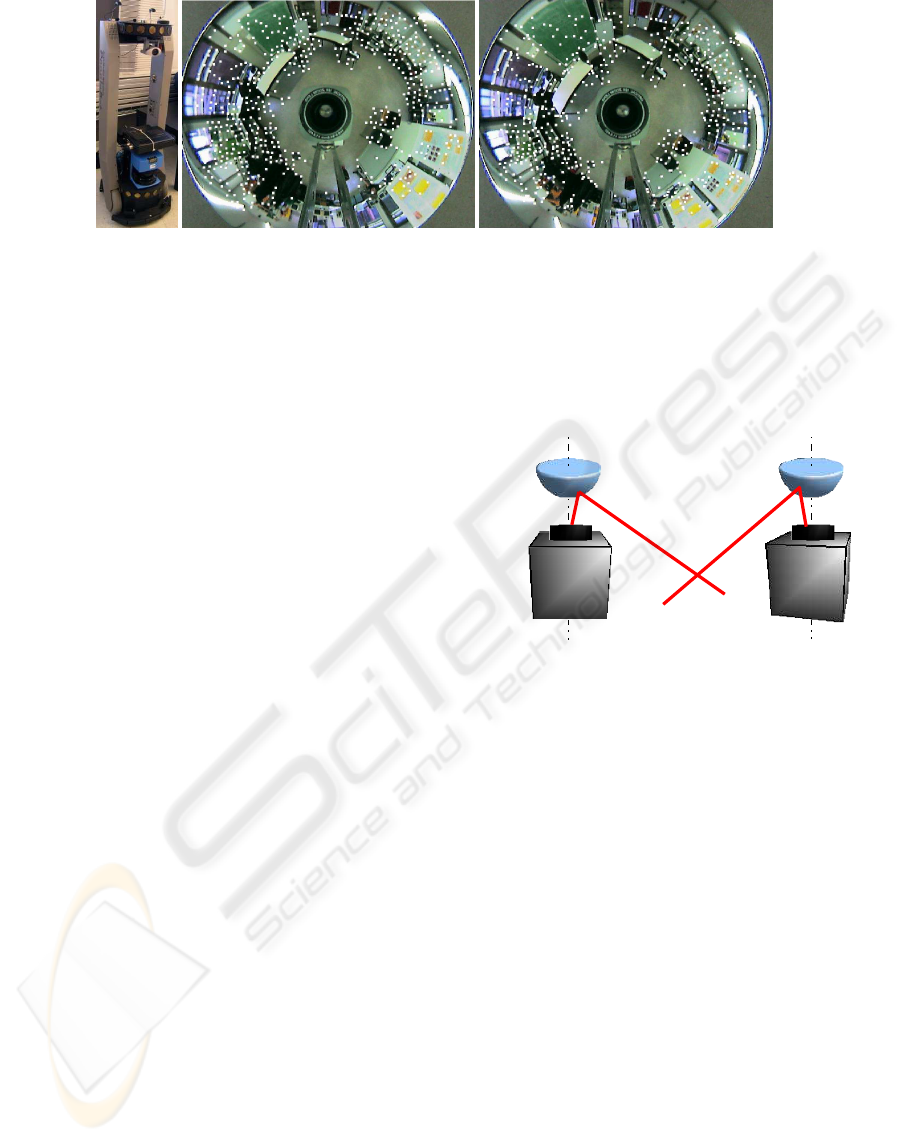
Figure 3: Left: The peoplebot robot. Right: The tracked features in two images with one second delay or fifteen images apart.
tees optimal tracking. A point is selected if the matrix
g
2
x
g
x
g
y
g
x
g
y
g
2
y
, (1)
containing the partial derivatives g
x
and g
y
of the im-
age intensity function over an N × N neighbourhood,
has large eigenvalues. Tracking is then based on a
Newton-Raphson style minimisation procedure using
a purely translational model.
3.3 Epipolar Geometry Estimation
The standard epipolar geometry has been developed
for perspective cameras, (Hartley, 2000). Since we
are using panoramic cameras a few prior steps are
needed in order to use the same algorithms.
The epipolar geometry for panoramic cameras is
depicted in fig. 2. The epipolar plane is defined by
the points where rays reflect on the mirror surface
and not, as for ordinary cameras, by the image plane
coordinates. Therefore it is necessary to backproject
the image plane coordinates up onto the mirror shape.
The epipolar geometry is then established with a pro-
cess called Generate and Select, see (Svoboda, 1999).
Generate and Select resembles the popular RANSAC,
but it is not random as the process ranks the corre-
spondences before it starts computing the essential
matrices. The ranking reduces the number of com-
binations that need to be tried out.
3.4 Triangulation
When the epipolar geometry has been established the
translation vector t and rotation matrix R, see fig. 2,
can be computed with standard methods, (Hartley,
1992). This yields the necessary information to de-
termine the relative positions of the 3D coordinates,
up to an unknown scale factor, done by triangulation.
The triangulation process, see fig. 4 determines the
positions by finding where two rays, back projected
from each image centre going through respective mir-
ror correspondence, intersect. The triangulation for-
mula derived is based on the notion that the smallest
distance between two rays has a direction perpendic-
ular to both rays.
Figure 4: Triangulation for panoramic cameras.
3.5 Scale Determination
To determine the absolute location of the relative 3D-
coordinates, a known reference distance is needed.
This is typically achieved by measuring the baseline,
e.g. by an odometer. It was stated above that we in-
stead use the ground plane assumption together with
the easy measurable height of the camera system as an
absolute reference frame. If we can determine enough
points on the ground plane we can robustly compute
the scale factor.
This is accomplished by selecting the k lowest rela-
tive feature points. This is done by comparing the rel-
ative z-coordinates. Some of these might be outliers,
hence we need a filter. The filter works by computing
the Euclidean distances in the z-coordinate between
each feature and the average z-coordinates of the k-
features. If the distance is bigger than a threshold T
the feature is discarded. This step is then repeated
for the k-1 remaining features and iterated until all
features are within the predefined threshold T or we
have a minimum set of features. This filter step pre-
ICINCO 2006 - ROBOTICS AND AUTOMATION
368
vents features due to noise, bad triangulation etc. from
affecting the scale.
When the scale for one individual image has been
determined it is evaluated in the context of the prior
images. A Kalman filter, (Kalman, 1960) is em-
ployed to keep the scale stable throughout the image
sequence.
4 RESULTS
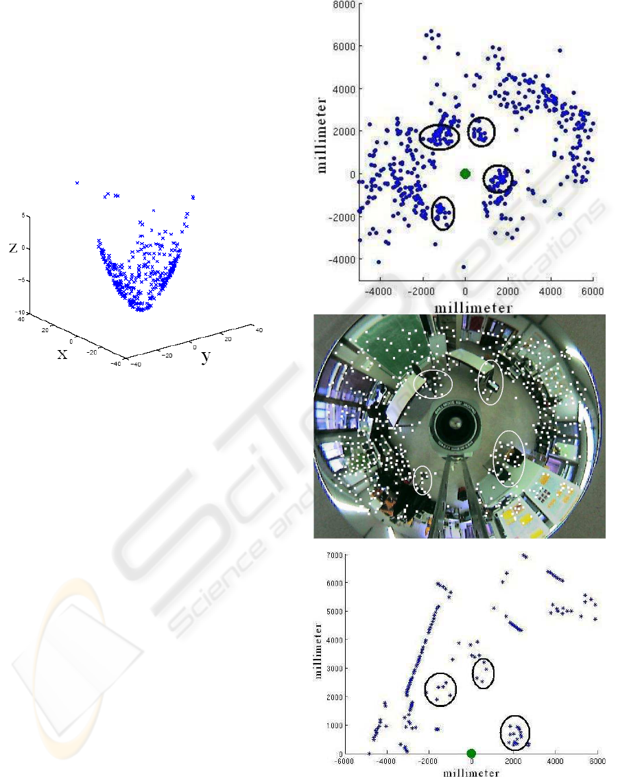
Figure 5: The mirror projection.
Our method is evaluated by comparing it with a SICK
laser scanner. The experimental set up is composed
of a mobile robot, a peopleBot by ActiveMedia fig. 3,
and an omnidirectional viewing system (consisting of
a Sony firewire colour camera and a hyperbolic mir-
ror). The camera system is fully calibrated. The mo-
bile robot has a SICK laser range scanner built in.
Images were captured at a frame rate of 15 f/s and
each image has a resolution of 640×480 pixels. The
laser scanner has a field of view of 180
◦
and makes
scans at approximately 5Hz. The images were cap-
tured while the robot was driving through a natural
environment at a relatively high speed. This paper
presents two representative images from the experi-
ment, see fig. 3. The disparity between the images are
approximately 40 cm. The visual features captured
in each image were tracked through a sequence of 15
images. In each tracking sequence 1000 features were
tracked. After the feature matching the features were
backprojected onto the mirror shapes, fig. 5. After the
mirror coordinates have been established the epipo-
lar geometry and the rotation and translation between
the two views were determined. Then the relative 3D-
coordinates were computed.
Figure 6: The cameras output, the tracked image and the
laser output.
RANGE DETERMINATION FOR MOBILE ROBOTS USING ONE OMNIDIRECTIONAL CAMERA
369
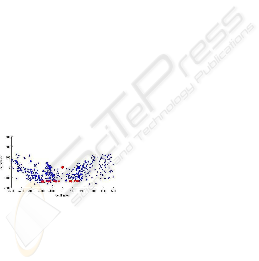
To determine the scale, the 30 lowest features were
located and evaluated with the method described in
sec. 3.5. In fig. 7 the resulting features are shown, the
bigger red dots indicate the assumed ground plane.
It is seen that a few lower points are filtered out. The
height of the camera system is also seen on the y-axis.
The measured height of the system is 140 cm. The
vertical field of view is also displayed well.
In fig. 6 our method’s output can be visually com-
pared to that of the laser scanner. The middle im-
age is one of the tracked images, the left image is
our method’s output and the right image is the laser
scanner’s output. The circled areas are correspond-
ing areas showing obstacles. It can be seen that our
method gives much more information about the sur-
rounding area than the laser scanner, it may though
appear noisy. This is due to that features from up to
108
◦
vertically are projected down on to the ground
plane. Looking at the top left ellipse in fig. 6 it is seen
that the laser scanner only detects very few features
around the table and chair while our method is able
to detect the full shape. It can also be seen that the
feature tracker we use is somewhat limited to sharp
edges. Compared to the laser scanner it still detects
more features and obstacles in the scene. When the
laser scanner is limited to one half plane our algorithm
detects obstacles in a bigger area of the sphere, i.e.
the lower left ellipse in fig. 6. It can also be seen that
while the laser scanner is more accurate, our method
detects more features on every obstacle, i.e. a more
reliable detection of obstacles.
Figure 7: Side view of the 3D-positions of the features.
The bigger red dots indicate features on the assumed ground
plane.
5 CONCLUSIONS
This paper presents a successful approach of deter-
mining absolute 3D-distances in the scenes. The pro-
posed method uses a single omnidirectional camera
to compute absolute distances in the scene. The exact
scale is determined by assuming that the robot moves
in one plane and measuring the height of the cam-
era. The height is easily accessible, which makes our
method cheap and easy to implement. Our algorithm
is compared with the output from a SICK laser range
scanner. The results show that our approach gives
more information about the scene and is able to locate
more obstacles than the laser scanner. The laser scan-
ner is more accurate but limited to data in only one
half plane, while our algorithm is able to detect obsta-
cles in 360
◦
×108
◦
of the surrounding sphere. This
makes our approach more reliable in ways that it de-
tects a wider range of obstacles, e.g. table tops, over-
hanging cupboards etc. The current version might not
be accurate enough for industrial applications, but for
service applications, e.g. wheelchairs, the accuracy is
not crucial. It is though a good candidate to replace
the laser scanner with for some applications.
Advantages of a laser range scanner compared to
our method are as follows; It detects obstacles regard-
less of translation, speed or rotation. It works in any
light condition and it detect obstacles regardless of the
texture of the scene. Our method relies on detecting
corners. In order to detect corners our system needs
scene with texture.
The speed of our method is currently 1Hz. This
can be seen as the lower bound since we have not yet
performed any optimisation. The optimised algorithm
will have a speed comparable to the laser range scan-
ner’s 5Hz.
Future work includes, apart from optimisation, to
combine our algorithm with the laser scanner and in
this way make it reliable enough for industrial appli-
cations. We also need to perform additional experi-
ments to see if the wheelchair can navigate solely on
the camera.
ACKNOWLEDGEMENTS
This work has been supported by the Inter-University
Attraction Poles, Office of the Prime Minister (IUAP-
AMS), the Institute for the Promotion of Innovation
through Science and Technology in Flanders (IWT-
Vlaanderen), the Fund for Scientific Research Flan-
ders (FWO-Vlaanderen, Belgium), and the K.U. Leu-
ven Research Fund (GOA-MARVEL). A. H
¨
untemann
is research assistant of the research foundation Flan-
ders FWO.
REFERENCES
T. Goedem
´
e , M. Nuttin, T. Tuytelaars, L. Van Gool 2005
Omnidirectional Vision based Topological Navigation
15th International Symposium on Measurement and
Control in Robotics, ISMCR 2005, 2005.
A. N
¨
uchter, K. Lingeman, J. Hertzberg and H. Surmann
2005 Heuristic-based laser scanner matching for out-
ICINCO 2006 - ROBOTICS AND AUTOMATION
370

door 6D SLAM Advances in artificial intelligence.
28th German Conf. on AI, Sept. 2005
Julian Ryde and Huosheng Hu 2006 Mutual Localization
and 3D Mapping by Cooperative Mobile Robots IAS-
9, The University of Tokyo, Tokyo, Japan, 2006
R.A Jarvis 1983 A perspective on Range Finding Tech-
niques for Computer Vision. IEEE Transaction on pat-
tern analysis and machine intelligence, VOL. PAMI-5,
No. 2, March 1983
T. Svoboda 1999 Central Panoramic Cameras Design, Ge-
ometry, Egomotion. Ph.D. disseration, Center for Ma-
chine Perception, Department of Cybernetics, Faculty
of Electrical Engineering of Czech University
R. Hartley 1992 Estimation of relative camera positions
for uncalibrated cameras. 2nd ECC, May 1992, pp.
579-587, Springer-Verlag, LNCS 588.
J.S Chahl and M.V Srinivasan (1997). Range estimation
with a panoramic visual sensor. In J. Opt. Soc. Am/A
Vol.14 No. 9 2144, Sept 1997.
J. Zhang and K. Huebner 2002 Using symmetry as a fea-
ture in panoramic images for mobile robot applica-
tions. In VDI-Berichte 1679, GMA-Robotik 2002,
Ludwigsburg 2002.
R. Hartley and A. Zisserman 2000 Multiple View Geome-
try in Computer Vision. Cambridge University Press,
2000
C. Mei 2006 http://www-sop.inria.fr/icare/..
/personnel/Christopher.Mei/index.html
cited 2006/12/10.
J. Shi and C. Tomasi Good Features to Track CVPR, Seat-
tle, pp. 593-600, 1994.
Kalman R.E. A new approach to linear filtering and predic-
tion problems, Transaction of the ASME - Journal of
Basic Enginnering, pp. 35-45, March 1960.
RANGE DETERMINATION FOR MOBILE ROBOTS USING ONE OMNIDIRECTIONAL CAMERA
371
