
A Workflow Model For Integrating IC Design and
Testing
Andres Mellik
1
1
Tallinn University of Technology, Department of Electronics,
Ehitajate road 5, 19086 Tallinn, Estonia
Abstract. This paper outlines the challenges facing the domain of automated
testing of mixed-signal integrated circuits and how these can be tackled by en-
hancing communication between the design and test engineers. An abstract
workflow model is introduced for seem-less interaction of design and test
teams, thus enabling faster work-flow and a greater redundancy in the correct-
ness of communicated specification data. The latter is embedded into a system-
level model and completely integrated into the process. A data-sheet integration
methodology is briefly introduced with several application-level requirements
and integration guidelines. The goal is to reduce the time for developing and
running test programs, which is a major cost factor in the reducing life-cycles of
mixed-signal devices. The paper emphasizes obstacles in current settings and
suggests workarounds.
1
1 Introduction
Decreasing the time required for testing an integrating circuit is vital for any semicon-
ductor company. Developing the (automated) test programs and running tests from
simulation and prototype to production phases are major investments in terms of
working hours and automated test equipment utilization. A multitude of factors should
be considered in order to increase the effectiveness of such a design and test process.
Several are mentioned in this paper, defined as “challenges”.
There is a consensus among the test community to increase abstraction in dealing
with such obstacles. This refers to a clear need for a system-level approach, which will
be described and elaborated on in the following chapters. As complexity is growing in
circuits, that have analog and digital modules combined onto a single chip or System-
on-Chip, we need to increase the abstraction in dealing with these designs by the same
margin.
Various methods have been proposed and experimented with considerable success.
Nevertheless, most of the issues touched upon are still in research phase and hopefully
the work outlined in this paper can provide support for implementation guidelines.
1
This paper addresses the preconditions and work-flow issues deriving from a more compre-
hensive work on increasing abstraction for automated test generation for mixed signal inte-
grated circuits and devices.
Mellik A. (2005).
A Workflow Model For Integrating IC Design and Testing.
In Proceedings of the 2nd International Workshop on Computer Supported Activity Coordination, pages 103-108
DOI: 10.5220/0002558901030108
Copyright
c
SciTePress

1.1 Challenges
The demand for mixed-signal integrated circuits is increasingly growing. Within the
next five years the number of transistors per cm
2
is expected to rise from ~40 to ~180
million, a factor of 4.5 times, [1]. This will directly impact the complexity of these
devices. Even though the packaging of such chips has evolved with the introduction of
ball-grid-array and quad-flat-package, [2] the increase in pin-count is expected to be
none higher than from current ~1500 to less than 3000 external pins, a factor of less
than two times. The ratio of the two clearly outlines a need for increasing abstraction
in the (automated) test of these circuits.
An ever-occurring challenge in manufacturing an integrated circuit is the communi-
cation between the design and test engineers. With the emergence of complex mixed-
signal designs, effective communication is critical for a successful work-flow, consid-
ering the shortening life-cycles of such products. Nevertheless, passing specification-
related information from designers to test personnel is often realized through simple
tools like e-mails or verbal communication. The specifications tend to be static files,
with multiple versions going back-and-forth. In such manner, information can easily
get distorted or even lost.
Conclusively from the above, the concept of design-for-test (DfT) is often mentioned
but more seldom implemented in its intended form – to enable testing of product func-
tionalities at all levels and phases of the design.
Several other specific complexities exist in the domain, such as modeling the input-
output relations of mixed-signal designs and their building blocks, dealing with noise
under low-power requirements and increasing clock rates. Additionally frequent
(test)signal passing through the analog-digital and digital-analog divide requires
propagation of analog signals through digital modules and vice versa, introducing
complex, but promising results. The latter problems and proposed methods for over-
coming are not explicitly described in the following sections, thus they would draw
the focus from the abstractive perspective offered.
2 System-level Work-flow
There is a need for an abstract model of the design consisting of functional blocks,
also referred to as the basic blocks, [3]. The model should be developed in parallel
with the actual design, which would enable the design and test engineers to tackle aris-
ing problems as soon as possible. This interaction is the starting point of an already
established DfT process which is ideally maintained throughout the whole life-cycle of
a product. Following Figure 1, a re-iteration of a model-based design approach pro-
posed in [4], proposes the workflow model, some aspects of which will be discussed
in the following chapters.
104
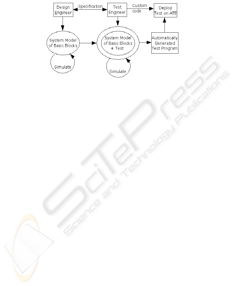
Fig. 1. Work-flow of a design and test process with an integrated system level specification
The above Figure 1, originally developed for the design of an aircraft control system,
points to similar efforts in various engineering disciplines.
The model outlines the roles of both the inter-actors (design and test teams), with
the actual (specification) data being communicated, used directly in generating a sys-
tem model of the design. The system model consists of functional basic block models,
which carry as many parameters with tolerances as required for a particular propaga-
tion and/or measurement in a certain phase of the test-run. In addition they should be
identifiable within the signal paths through indexing or describing previous and fol-
lowing basic blocks, to preserve observability and controllability for all relevant pa-
rameters. Certainly a pre-analysis of the entire model needs to be conducted before-
hand, to identify those parameters. Such methods, proposed in [5], lay the ground-
work for actually pursuing an automatically generated test (program) for a mixed-
signal circuit.As the design and test process phases are iterated, simulated and proto-
typing carried out, the goal is towards a dynamically updated specification, hence
keeping a keen eye on all of the changes, however marginal, are being added into the
information set. Such electronically supported method adds a higher redundancy into
dealing with critical design data, while removing irrelevant overhead data from the
communication.
Therefore the described work-flow contributes toward inter-human communication
supported by a virtual information system, enabling to speed up the process and
achieve human fault elimination – a cause for far too many project failures and missed
deadlines.
3 Data-sheet Integration
A specification or data-sheet of a design is to-date viewed as the means of describing
the overall functionality and characteristics of a device, including operating condi-
tions, electrical parameters, thresholds, etc. While it maybe sufficient, in terms of
automatic test generation for relatively simple devices, such data-sheets carry less
advantages for the test team. It is too extensively considered a marketing tool, rather
than a possible tool in product validation.
105

Our starting point is the specification of a mixed-signal design. A problem often
facing the interaction of the design and test teams is the presentation and format of the
product specifications. These specifications are not always delivered to the test team
in a consistent format. This is drawing additional time resources from the test engi-
neers to manually transfer ratings, electrical and performance characteristics and other
information from the data-sheets to the test program.
The terms “specification” and “data-sheet” would in this case refer to the same col-
lection of data, necessary for a DfT process. We expect this data to include informa-
tion on the system model, basic blocks and sets of blocks, possible signal paths, etc.
We propose creating a unified data-sheet format to be followed from the beginning
of the design phase to the product delivery and throughout the product portfolio. In an
actual corporate environment this would entail first carrying out a data-sheet uniform-
ity analysis, to determine the mappings from current setting to a standard format. The
format alone is of little use to the automated test process. The format and the software
should ideally meet all of the following criteria:
1. A widely accepted, customizable structured data format (XML).
2. Easy insertion and extraction of data.
3. Interface with modeling, design, simulation and test environments.
4. Standard representation:
1. web: HTML
2. print: PDF
5. Quick comparison of files by any parameter(s)
Point 5 in the list outlines an important requirement to promptly create a compari-
son chart of similar products. When data-sheets are given solely as PDF-documents,
this is not easily done, as extracting text and data from a portable document can be a
tedious task. Using an approach to generate this from XML files makes the process
not only faster but also customizable.
The use of a database back-end is not recommendable as it makes the process de-
pendent on yet another component. Implementing the software to support both local
and remote data-sheet repositories is a sufficient solution.
The use of XML carries another major advantage, as it can be interfaced with little
effort with the design and test environments. Using a centralized repository for data-
sheets enables the test engineer to obtain the latest changes in the specification auto-
matically, which increases positive redundancy in the communication between the
design and test engineers. An automatic notifier for latest changes would also keep
both sides up-to-date. A fact, that XML has evolved to become the de facto standard
for communicating customized information, ultimately makes it a logical choice. Fu-
ture work will include applying this concept to a fairly simple mixed-signal design,
consisting of 4-5 basic blocks, to evaluate the approach.
Following Figure 2 depicts the proposed data-sheet approach.
106
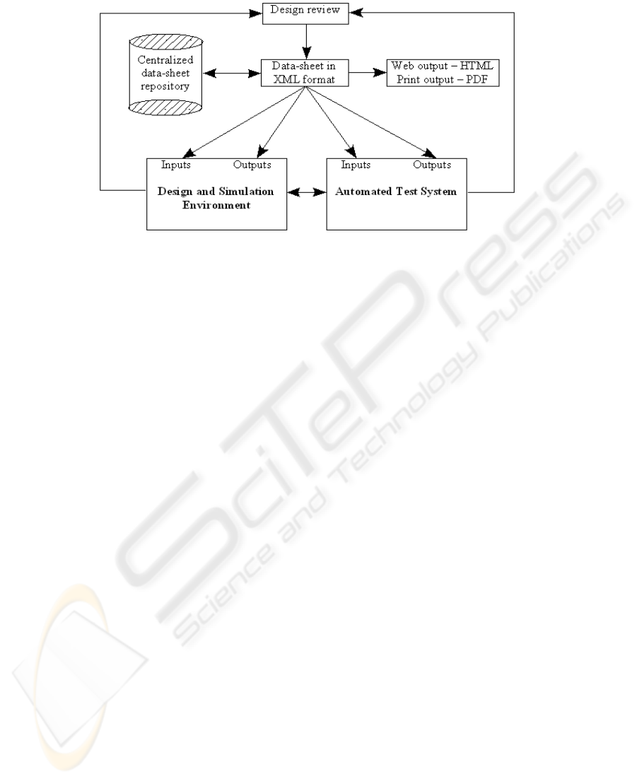
Fig. 2. XML-based data-sheet integration into an iterative design and test process.
The above Figure 2 also visualizes the idea of application level integration and target-
ing less compexity in the IC automated test development process.A strong advantage
for selecting a non-proprietary format for data-sheets is the possible adoption among
the academic community. Several (free) tools exist to process such files, such as Xer-
ces, DOM, XML::Parser for Perl, etc - bringing out the easy-to-handle properties of
the proposed format.
The following structure shows a sample XML-file, describing basic blocks of a
model with the name, classification and index of the block, together with required
parameters and tolerances. A simplified version of an actual XML-based system
model specification, it introduces a much needed hierarhical structure. With browsers
supporting navigating through XML by enabling to open and close sub-levels, it is
convenient for understanding the architecture, sequence and specific parameters.
Example XML-file describing basic blocks within a model, identified by name, class and index.
Parameter set is „closed“ in the second block (LPF).
-<MODEL>
-<BASICBLOCK>
<NAME>AMP</NAME>
- <DATA>
<INDEX>1</INDEX>
<CLASS>Analog</CLASS>
-<PARAMETERS>
<PARAM_1>Gain</PARAM_1>
<PARAM_1_VALUE>2.3</PARAM_1_VALUE>
<PARAM_1_TOL>0.1</PARAM_1_TOL>
</PARAMETERS>
</DATA>
</BASICBLOCK>
-<BASICBLOCK>
<NAME>LPF</NAME>
+<DATA></DATA>
</BASICBLOCK>
</MODEL>
107

4 Application Level
Without referring to any COTS products, using already established modeling, design,
simulation and measurement environments to implement the design and test flow in-
troduced in the previous chapters, carries several advantages both for academic insti-
tutions and corporations. These tasks include:
1. Parametric input from the specification
2. Modeling and simulation of basic blocks
3. Input Signal Propagation, Output Measurements
4. I/O with the DUT (switch matrix control)
5. Results acquisition, analysis and storage
Refer back to Figure 2 for some inter-connections between the above-listed tasks.
Re-using environments capable of handling the above tasks would enable to leverage
the existing competence of applications at a site, rather than vesting resources in de-
veloping an additional design and test software for the purpose.
5 Conclusions
Though this paper targets work-flow improving for a particular domain, namely the
automated test generation for mixed-signal integrated circuits, the author is confident,
that the actual concepts introduced are applicable to several others. With quality and
reliability counting for a major portion of a products overall success, increased and
more efficient interaction between design teams and quality assurance (testing) teams
becomes inevitable. In an ideal view, the two processes should have more and more
overlaps with both providing feedback and input into one another.
Utilizing a set of existing and future technologies and applications to bring this in-
teraction to life, enables for any entity with such needs to begin experimenting and re-
defining their work-flow models promptly.
References
1. J.A.Ochoa and J.R.Porter, “Semiconductor Test Strategies”, IEEE Instrumentation & Meas-
urement Magazine, pp.20-25, March 2003.
2. M. Bushnell and V. Agrawal, “Essentials of Electronic Testing for Digital, Memory, and
Mixed-Signal VLSI Circuits”. Norwell, MA: Kluwer, 2000.
3. S. Ozev and A. Orailoglu, „Path-Based Test Composition for Mixed-signal SOC's“ , South-
west Symposium on Mixed Signal Design, San Diego, CA, pp. 153-158, February
2000.
4. Mathworks, “Model-Based Design of Embedded Control System Software” URL:
http://www.mathworks.com/wbnr5216, November 2004.
5. S. Ozev and A. Orailoglu, „Automated System-Level Test Development for Mixed-Signal
Circuits“, International Journal on Analog Integrated Circuits and Signal Processing, v. 35,
n.2-3, pp. 169-178, May-June 2003.
108
