
CONTROL FOR ELECTRICAL NEUROMUSCULAR
STIMULATOR USING FUZZY LOGIC
Trainning gait in paraplegics
Leonardo Rodrigues da Silva, Percy Nohama
Depto. de Eletrônica, CPGEI, Centro Federal de Educação Tecnológica do Paraná (CEFET/PR), Curitiba, Brazil
Keywords: Electrical stimulation, fuzzy logic, closed loop, electrical goniometers, spinal cord injury, artificial gait.
Abstract: This article presents a personal computer-based control system for an electrical stimulator using fuzzy logic.
The input signal comes from a goniometer and the output is the stimulation level to be applied in the muscle
of the patient. By this way, that control system is made for the therapist that just specifies the desired joint
angle. The movement that the patient will execute can be imitated from a person with normal movements,
storing his or her joint’s angles during the execution of some task, and later reproducing it in the person
without the voluntary movements. Such movements will be more proper of a human than a planned
execution of a computational system, which the movement is structuralized by means of vectors, angles and
times placed of supposed form.
1 INTRODUCTION
The electrical neuromuscular stimulation is the most
adjusted technique to be applied in cases of
atrophied muscle due to the lack of movements
caused mainly by spinal cord injury or vascular
encephalic accident because it can cause
development and increase of muscular strength, even
in those without a voluntary contraction (Quevedo at
al., 1997).
During and after the development of muscles, it
is possible to make the body get used to certain
movements and create a sensorial engram, so that
lately it comes to execute such movements in an
intuitive way, without the necessity of electrical
stimulation.
A closed loop electrical stimulation system using
goniometers as input is described by Quevedo and
Cliquet Jr. (Quevedo & Cliquet Jr., 1995), who
presented an ideia of neural networks-based control,
which presented the disadvantage of needing to
much time for the network’s training for each type
of movement.
In 1998, Zagheni (Zagheni, 1998) developed a
multi-channel computer controlled neuromuscular
electrical stimulation system which by operating in
open loop and containing 8 analog inputs that allow
processing of electrical physiologic signs,
consequently, served as feedback inputs and, thus, to
control the stimulation parameters automatically.
This article presents a new strategy of control
applied to Zagheni’s stimulator, based in fuzzy
logic, aiming to improve the control of the
stimulation and to facilitate its use in the engram’s
development. This control system was developed
with the objective of monitoring the position of the
stimulated member. Using as input, the signals from
electrical goniometer coupled in the joints under
control and the target position, are obtained as
output the amplitude of the stimulatory signal to be
applied on the muscle, via transcutaneous electrodes.
The in-vivo tests were applied to 4 paraplegic
volunteers, controlling the knee extention and hip.
During the tests two goniometers were used,
controlling both knees independently or one knee
and the hip, in this case being applied the same
stimulation to both legs, standing the volunteer up.
According to W. Dalton Dietrich, Scientific
Director of the The Miami Project to Cure Paralysis,
at the University of Miami School of Medicine,
there are 5 steps for the cure to spinal cord injury:
1 - patient selection and pretraining; 2 - surgical
intervetions and neuroprotection; 3 - tranplantation /
regeneration; 4 - overcoming barriers to regeneration
and 5 - rehabilitation (Dietrich, 2005). The system
presented in this article could be used in steps 1 and
5.
266
Rodrigues da Silva L. and Nohama P. (2005).
CONTROL FOR ELECTRICAL NEUROMUSCULAR STIMULATOR USING FUZZY LOGIC - Trainning gait in paraplegics.
In Proceedings of the Second International Conference on Informatics in Control, Automation and Robotics, pages 266-269
Copyright
c
SciTePress
2 PROBLEM FORMULATION
The possibility of the spinal cord injury
rehabilitation could come in a near future. Some
researches are already bringing concrete results in
guineas pigs, like the implantation of stem cells
(Rosano et al., 1999) and cells of Schwann (Oudega
et al., 2001), making a backup of the communication
between the brain and the remaining portion of the
body below of the part affected by the injury
possible.
As for the integral rehabilitation of the disabled
person, we have necessarily to pass through the 5
steps described by Dalton Dietrich (Dietrich, 2005).
So, passing through the pre-training, where it is
needed to fortify the muscle and to verify the
possibility of muscles and bones to support the body.
Also after that possible regeneration of the spinal
cord, we go through a rehabilitation process by
which the not enough trained muscle passes through
the exercising process so that it can fulfill its role. In
these two stages, the use of the electrical stimulator
with closed loop control is important.
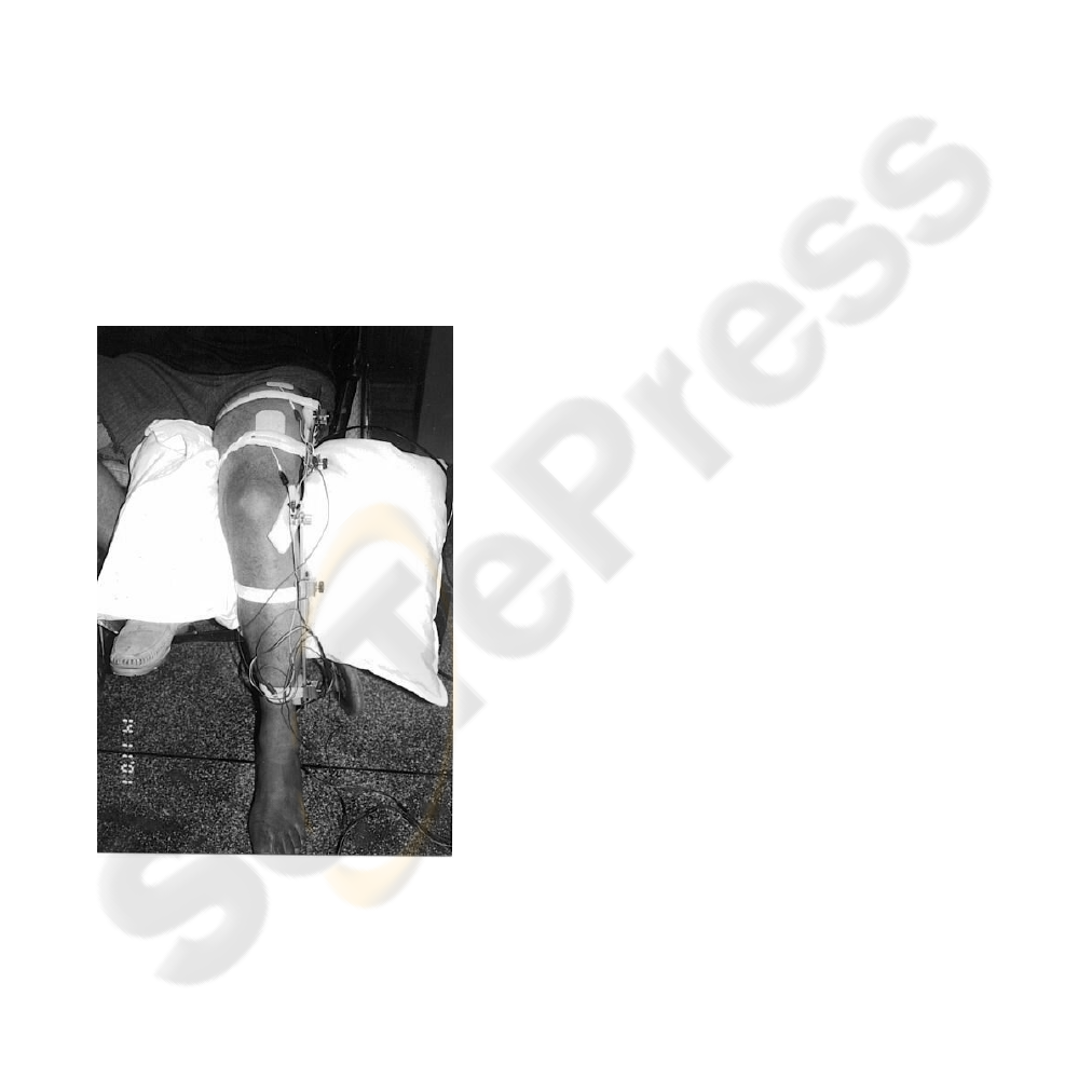
Figure 1: Pacient with electrical goniometer to control
knee joint
The feedback signal of the system is gotten from
one goniometer that measures the joint angle of the
inferior limb under control (fig. 1). The computer
has stored the path that the joint must execute. From
these two pieces of information, the system controls
the amplitude of the stimulation so that the limb
stays in the desired position in an instant of time
determined by the operator of the system. The
control system works according to objectives. The
therapist specifies the movement that the member
must execute, specifying the angle desired for each
moment.
The training for development of sensorial
feedback was applied in cats for the retrain of the
march. A full spinal cord injury was provoked at the
level T13, the locomotion capacity returned
gradually and in 1 to 3 weeks the cat started to have
the locomotion movements of posterior legs, being
able to hold its body’s weight (Rossignol et al.,
2000).
The theory of sensorial feedback is based on the
theory of the neural plasticity of the spinal cord,
from which it was concluded that, among other
things, the spinal cord drive the step processing
complicated sensorial information of the peripheral
nerves (APA, 1998). The training and the learning
are fully specific, because if a cat is trained to take a
step, it will take a step; if it is trained to stand still, it
will do so, but it will not take a step (Rossignol et
al., 2000).
The system can be applied to human beings with
problems in the central nervous system (CNS) so
that they can develop new abilities as it has been
demonstrated by Calancie (Calancie et al.), who says
that there is a central pattern generator (CPG)
located in the spinal cord for the generation of the
step. According to that, a person without voluntary
movements, after spending intensive physiotherapy
sessions walking, even lying down, kept the pattern
of gait, showing that the body had learned. As a
result, we can assume that after the stimulation of
the patient’s muscle to walk, he or she must learn to
do this alone.
3 PROBLEM SOLUTION
So that the system could be tested before its in-vivo
application, a muscle simulator was developed. It
gave some evaluation of the response for a real
stimulation. The simulator takes into consideration
the angle of the joint, the applied force and the
amount of fatigue beyond the amount applied
stimulation (Silva & Nohama, 2000,1)(Silva &
Nohama, 2000,2).
The system was initially developed in the
Simulink of the Matlab (Matlab, 5.2.0). Due to its
assembly, tests and alterations easinesses, besides
providing one easy interaction with the logic fuzzy
blocks used for the control and simulation system.
To establish the artificial gait using fuzzy logic,
first, the control of the knee extension was
developed with the patient sat, attempting an
CONTROL FOR ELECTRICAL NEUROMUSCULAR STIMULATOR USING FUZZY LOGIC - Trainning gait in
paraplegics
267
effective control of quadriceps muscles contraction
and, thereby, control the movement of the member.
The Zagheni’s software for the electrical
stimulator was developed using Visual C++.
Currently, we have upgraded that software with the
fuzzy controller algorithm in two channels of input
and sexteen channels of output, eight for each input.
In the present moment, it allows two goniometers
connected. Therefore, the knees joint and hip were
chosen for tests, made stimulating and controlling
the Rectus femoris, Gluteus maximus and Vastus
lateralis muscles, and used Gastrocnemius to help
stabilising when the volunteer stands up.
The triangular membership functions of the fuzzy
system had been chosen by being the most
commonly employed, being able to be adjusted later.
The controller was designed with an input called
angle input with 3 membership functions, another
input called the difference between active angle and
the desired one, with 5 membership functions and
the output is the difference of stimulation with 5
membership functions (Silva & Nohama, 2000,2).
In the output of the system fuzzy we had the
value to be calculated from the value currently
applied to obtain a new amplitude. To become the
generic system, at first model, all the values are
normalized (between 0 and 1), because the majority
of the parameters vary from patient to patient, thus,
the data needs to be processed for the input after an
output of the fuzzy system.
We did tests in-vivo to verify the necessity for
adjustments in membership functions. In the in-vivo
application we feel the necessity to establish a
minimum value of stimulation, because there is, in
each muscle of each patient, a sensibility threshold,
a contraction threshold value (when the muscle starts
to contract) and a maximum value of stimulation.
Above that maximum value, there is the risk to
cause damage to the muscle.
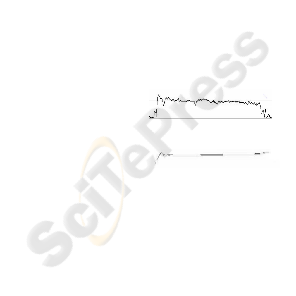
In one test a fixed angle of, more or less, 45
degrees was used as target of the member; the
member was initiating the motion with an angle of
more or less 85 degrees (fig. 1 and 2). That angle
was chosen due the difficulty to be kept during
electrical stimulation.
In figure 3, we have the amount of stimulation
applied to the muscle, we can notice the
compensation that the system makes due to the
fatigue that the muscle is submitted to during the
stimulation, also it is important to place that during
these tests, at any moment the stimulation arrived in
the maximum defined for that muscle, in that
patient. It had a small variation above and below the
objective angle that was left on purpose, because,
during our daily activity, the movements are not
totally precise, so an alteration of stimulation for
small natural variations in the contraction wasn’t
necessary.
The noise present in the input signal will be
filtered in the future.
So that the movement can be more natural and
can have the possibility of a bigger gamma of
movements, with more easiness of configuration, it
is in final phase of development be read the angles
of the joints from a person with normal movements
for posterior reproduction in one patient, through
electrical stimulation. With this feature, the
movement pattern is easier to be constructed than
that one through the planning of computational
systems, where related movements are structured by
means of vectors, on which angles and times are
placed in the way they’re supposed to. In this way,
the movement is better assimilated and later
reproduced through the process of the Central
Pattern Generator demonstrated by Calancie
(Calancie et al.) and also by already existing a
previously stored engram, when the person had the
normal control of its movements, helping the
rehabilitation work if the cure of spinal cord injury
had been discovered.
Figure 2: Leg’s angle during the electrical stimulation
Figure 3: Amount of stimulus applied at Rectus femoris e
Vastus lateralis
4 CONCLUSION
In the continuation, the number of goniometers will
be expanded to be possible doing a gait at a
paraplegic. It needs to make a better design of
goniometers to be better adjusted to each joint.
Assembling a major number of goniometers,
allows us to test more complex movements. The
loop of control is already prepared and software will
need small implementations making possible for the
patient to execute movements like walk, ride a
bicycle or go up stairs, depending only on the
correct pattern of the angles to be executed. For the
future, an input system to acquire the intention of the
patient can be installed (Kostov et al., 1995), to
ICINCO 2005 - INTELLIGENT CONTROL SYSTEMS AND OPTIMIZATION
268

make the system slave of patient volitions and not
only of what is pre-determined by it. The
improvement of this technique will represent a great
advance in the area of functional electric stimulation
for paralyzed members, making the practical
application of this therapeutical feature easier.
These innovations bring a new age in the control
of neuromuscular electrical stimulator, allowing a
person without the voluntary control of its
movements to imitate another one who have full
movements. It could give him or her a much more
worthy and calm life. By using techniques of
implantation of electrodes, which already exist,
through a surgery, apparent wires will no longer be
necessary. And with the movements soften than ones
gotten through the systems of control currently in
use, the deficiency can be unnoticed.
REFERENCES
A. A. F. Quevedo, A. E. Patla, and A. Cliquet Jr., A
Methodology for Definition of Neuromuscular
Electrical Stimulation Sequences: An Application
Toward Overcoming Small Obstacles., IEEE
Transactions on Rehabilitation Engeneering, Vol. 5,
No. 1, pp. 30-39, 1997.
A. A. F. Quevedo, and A. Cliquet Jr., A paradigm for
Design of Closed Loop Neuromuscular Electrical
Stimulator Control Systems., Artificial Organs,
Vol. 19, No. 3, pp. 280-284, 1995.
A. L. Zagheni, Sistema EENM Multicanal Controlado por
Computador para Aplicações em Locomoção
Artificial. Dissertação de Mestrado. CPGEI / CEFET -
PR. Curitiba, 30 abr 1998.
W. D. Dietrich, http://www.miamiproject.
miami.edu/miami-proje t/5steps.htm, 10 apr 2005.
C. Rosano, E. Felipe-Cuervo, and P. M. Wood.
Regenerative potential of
adult O1+ oligodendrocytes. Glia. Vol. 27, pp.189-
202, 1999.
M. Oudega,S. E. Gautier, P. Chapon, M. Fragoso, M. L.
Bates, J. M. Parel and M. B. Bunge, Axonal
regeneration into Schwann cell grafts within
resorbable poly(a-hydroxyacid) guidance channels in
the adult rat spinal cord. Biomaterials, Vol. 22, pp.
1125-1136, 2001.
S.Rossignol, at al., Locomotor plasticity after central tracts
or peripheral nerve lesions in the cat, Symposium on
Spinal Cord Plasticity, Abstracts, Nov 1998. Apud
http://graulab.tamu.edu/Spinal/ Plasticity.html, jul.
2000.
APA. Locomotor Training May Lead the Paralyzed to
Walk. American Paralysis Association, 35 ed.,
Summer 1998,
http://paralysis.apacure.org/publications/ pir35-
summer98.html#LocomotorTraining, 06 ago 1999.
B. Calancie, et al., Involuntary stepping after chronic
spinal cord injury. Evidence for a central rhythm
generator for locomotion in man. Brain, Vol. 117,
Issue 5, pp. 1143-1159.
L. R. Silva, P. Nohama, Controle de Eletroestimulador em
Malha Fechada e Simulação de Resposta Muscular
Utilizando Lógica Fuzzy, XVII Congresso Brasileiro
de Engenharia Biomédica, set 2000.
L. R. Silva, P. Nohama, Estimulador Elétrico
Neuromuscular empregando Lógica Fuzzy, Iberdiscap
2000 - Congresso Iberoamericano 3° de Comunicación
Alternativa y Aumentativa y 1° de Tecnologías de
Apoyo para la Discapacidad, Madrid, 2000
Software Matlab, version 5.2.0, The MathWorks Inc.
A. Kostov, B. J. Andrews, D. B. Popović, R. B. Stein, and
W. W. Armstrong, Machine Learning In Control Of
Functional Electrical Stimulation System For
Locomotion, IEEE Transactions on Biomedical
Engeneering, Vol. 42, No. 6, pp. 541-551, 1995.
CONTROL FOR ELECTRICAL NEUROMUSCULAR STIMULATOR USING FUZZY LOGIC - Trainning gait in
paraplegics
269
