
Model Synthesis from Imprecise Specifications
Bill
Mitchell
1
, Robert Thomson
2
, Paul Bristow
2
1
Department of Computing, University of Surrey, Guilford,
Surrey GU2 7XH, UK
2
Motorola UK
Research Lab, Viables Industrial Estate, Hampshire RG22 4DP, UK
Abstract. The paper defines a formal semantics for MSC scenarios that is a
weakening of the state semantics from [6], whilst permitting some additional se-
mantics in the spirit of Live Sequence Charts (LSCs) [4]. The semantics here
differs from that of LSCs in that mandatory behaviour is defined dynamically
within the domain of possible scenarios. This permits a semantics which uses
domain knowledge to define when compositions of imprecise requirements are
valid. This has been implemented by Motorola UK Research Labs, and is being
used in a pilot study for a new telecommunications mobile 3G handset.
1 Annotated Events
Industrial MSC [7] scenarios have rather imprecise compositional semantics. The paper
describes a weakening of standard model synthesis semantics ([1], [3], [6]) that permits
valid composition of imprecise scenario specifications. This work has been applied to
industrial requirements specifications in Motorola case studies.
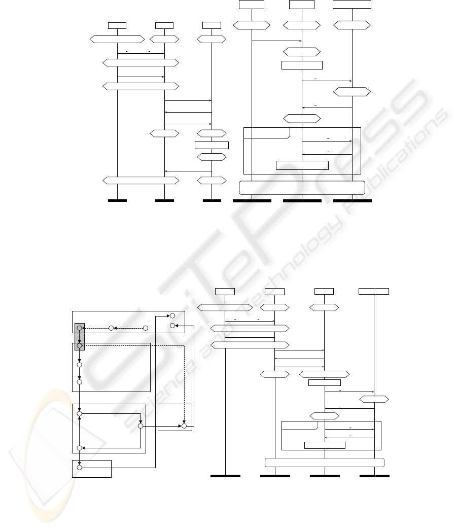
Consider the leftmost MSC in figure 1, which is a requirements scenario for a wire-
less mobile handset. This describes how a WAP ‘Browser’ process downloads a Java
application iteratively from the ‘Air Interface’ process until it receives the ‘EOF’ mes-
sage, or it detects that the file is corrupted.
The extended hexagonals are MSC condition symbols that describe which opera-
tional phase is active at any time. We will refer to them as phase symbols from now on.
Phase symbol labels will be identified with propositional boolean formulae in the paper.
An MSC defines a partial order semantics on the order that system events can be
observed to occur. A message m is translated into a send event !m and a receive event
?m.
Definition 1 Define T (P ) to be the set of traces generated by the process P in an MSC
M.
An event x in an MSC M occurs in the scope of phase symbol u if the first phase
symbol prior to x within the process it belongs to is u. Let P be the set of phase symbols
associated with an MSC M , and let ψ be a map that defines the set of phase names for
each symbol. I.e. ψ : P −→ 2
Ph
, where Ph is the set of phase names.
Where E is the set of events for an MSC M , let φ : E −→ Ph be the function that
maps each event e to the set of phases it belongs to, that is the set ψ(u), where e is in
the scope of u.
Mitchell B., Thomson R. and Bristow P. (2004).
Model Synthesis from Imprecise Specifications.
In Proceedings of the 2nd International Workshop on Verification and Validation of Enterprise Information Systems, pages 20-25
DOI: 10.5220/0002669500200025
Copyright
c
SciTePress
User
Phone
Browser
Java App Download
Idle
Inactive
key
press(java
menu)
Java Menu
select(option)
Download
activate
ack
load(URL)
Load File
Active
Download File
Download
download OK
Inactive
Display Notification
Phone
Browser
Air Interface
Download
Inactive
Channel
load(URL)
Active
Resolve URL
get
handle(file)
Data
file
handle(file)
Read File
read(file
handle)
send(file
handle)
Check For Errors
loop< 0, ∞ >
Alternatives Reference
Fig. 1. MSC Requirement Scenarios
?send(file_handle)
!ack
?load(URL)
?activate
Download
File
!download_OK
Resolve URL
!get_handle(file)
?file_handle(file)
!read(file_handle)
Check For Errors
Check For Errors
corrupt_file(file)
?EOF
Inactive
Active, Load File
Read File
Error Found
Download
User
Phone
Browser
Air Interface
Java App Download
Idle
Inactive
key
press(java
menu)
Java Menu
select(option)
Download
activate
ack
load(URL)
Load File
Active, Load File
Resolve URL
get
handle(file)
Data
file
handle(file)
Read File
read(file
handle)
send(file
handle)
Check For Errors
loop< 0, ∞ >
Alternatives Reference
Fig. 2. Phase Automaton, and Overlap Scenario
21

Definition 2 Define the phase traces for a process P in an MSC scenario M to be
sequences of triples:
(S
0
, e
0
, S
1
) (S
1
, e
1
, S
2
) · · · (S
n
, e
n
, S
n+1
)
where e
0
, . . . , e
n
is an event trace of P , S
i
⊆ Ph, φ(e
i
) = S
i
, and S
n+1
is the last
phase for process P in the scenario M.
Each triple in a phase trace is referred to as an annotated event.
2 Dynamic Constraints
A temporal model T consists of a directed graph G, with vertex labelling ν : G
V
−→
2
Ph
, edge labelling ε : G
E
−→ E, and some vertex i that represents the initial moment.
Temporal formulae are defined as usual:
– T, v ² heiφ iff there is an edge (v, w) ∈ G
E
such that ε(v, w) = e, and T, w ² φ
– T, v ² [e]φ iff for every edge (v, w) ∈ G
E
where ε(v, w) = e, T, w ² φ
– T, v ² ¤φ iff T, v ² φ and T, w ² ¤φ for every edge (v, w) ∈ G
E
– T, v ² ♦φ iff there is some vertex w reachable from v such that T, w ² φ
The satisfiability of ordinary boolean formulae is defined as usual. Formula φ is satisfied
in T when T, i ² φ. φ is valid when it is satisfied in every model, when we write ` φ.
Definition 3 For a set S ⊆ Ph, define
V
S =
V
x∈S
x. For a phase trace t = (S, e, S
0
)·
t
0
, define its temporal semantics as
ktk =
^
S ∧ hei(
^
S
0
∧ kt
0
k)
A context C is any temporal formulae over P and E.
A temporal context controls how phases are related across the requirements scenarios.
Definition 4 For context C we define phase trace t to match phase trace t
0
when
` C ⇒ (ktk ⇒ ♦kt
0
k)
Intuitively t matches t
0
if after some initial delay, t
0
becomes the same as t within the
context defined by C.
Definition 5 Let a = (S, e, S
0
) be an annotated event. When 6` C ⇒ (
V
S ⇒
V
S
0
)
define a to be a phase transition event.
Define a phase transition trace to be a trace of annotated events terminating with a
phase transition event.
Let t
1
be the phase transition trace of the phase trace t
0
consisting of t
1
=
({Inactive}, ?activate, {Inactive}) ({Inactive}, !ack, {Inactive}) ({Inactive},
?load(URL), {Active})
In the rightmost MSC of figure 1 the initial annotated event of process ‘Browser’ is
t
2
= ( {Inactive}, ?load(URL), {Load File}).
From this we can prove ` ¤([load(URL)](Active ⇒ ‘LoadFile
0
)) ⇒ (kt
1
k ⇒
♦kt
2
k).
22

3 Phase transition simulation
P | Q = P ¢ Q + P ¤ Q
a · P ¢ b · Q = a · P ¢| b · Q if a A
C
b
a · P ¢ b · Q = a · (P ¢ b · Q) if a 6A
C
b
P ¤ Q = Q ¢ P
0 ¢ Q = 0
a · P ¢| b · Q = (a ∪ b) · (P ¢| Q) if a A
C
b and ¬η
C
(a)
a · P ¢| b · Q = (a ∪ b) · (P k Q) if a A
C
b and η
C
(a)
a · P ¢| b · Q = a · P + b · Q if a 6A
C
b and η
C
(a)
a · P ¢| b · Q = a · P if a 6A
C
b and ¬η
C
(a)
0¢| Q = 0
a · P k b · Q = (a ∪ b) · (P k Q) if a A
C
b
P k Q = Q k P
0 k Q = Q
a · P k b · Q = a · P + b · Q if a 6A
C
b and b 6A
C
a
Fig. 3. Phase Transition Process Algebra
For annotated events a = (S, e, S
0
) and b = (U, g, U
0
) define a A
C
b when e = g,
` C ⇒ (
V
U ⇒
V
S) and ` C ⇒ (
V
U
0
⇒
V
S
0
). Define P to simulate process Q
within context C, written as P A
C
Q, if ∀a such that Q
a
−→ Q
0
there is some a
0
where
P
a
0
−→ P
0
such that a
0
A
C
a and P
0
A
C
Q
0
.
For annotated events a
i
and phase trace t = a
0
· a
1
· · · a
n−1
, let P
t
−→ P
0
denote
that there are processes P
i
, for 0 ≤ i ≤ n, such that P
i
a
i
−→ P
i+1
, P
0
= P and
P
n
= P
0
.
Definition 6 Define P to simulate the phase transitions of process Q within context C,
written as P D
C
Q, when the following holds. For all phase transition traces t such
that Q
t
−→ Q
0
, and for all phase traces τ that match t, whenever there is a process P
0
such that P
τ
−→ P
0
then P
0
A
C
Q
0
.
Definition 7 Let {M
i
| 0 ≤ i ≤ n} be a set of scenarios, let Q
i
be a process from
M
i
for each i. That is each Q
i
defines exactly the observed behavior of one process in
scenario M
i
.
We define process P to be the phase transition representation of processes Q
i
when
P D
C
Q
i
for each i. Define the overlaps of P to be those phase transition traces of P
that are not contained in any of the Q
i
.
4 Phase Transition Processes
In figure 3 we briefly describe a process algebra that defines how to synthesise a phase
transition representation from a set of processes described by the requirements scenar-
ios.
23

Let A be the set of annotated events. Let η
C
: A −→ B be a boolean valued function
that defines when an annotated event is a phase transition. That is η
C
(S, e, S
0
) = t when
6` C ⇒ (
V
S ⇒
V
S
0
). For annotated events a = (S, e, S
0
) and b = (U, e, U
0
) define
a ∪ b = (S ∪ U, e, S
0
∪ U
0
).
Proposition 8 Given a set Q of processes Q
i
from requirements scenarios M
i
for 0 ≤
i ≤ n, then
P = Q
0
| Q
1
| · · · | Q
n
is a phase transition representation of Q. Where | is defined by the axioms of figure 3.
If P
0
is another phase transition representation of Q, then P
0
A
C
P . That is P is
canonical up to simulation equivalence. Define P to be the phase transition process for
Q.
Figure 2 describes one of the overlaps given by the phase transition process of the
‘Browser’ processes in figure 1.
Definition 9 A phase automaton consists of a set of events E, states P and transitions
from P × E × P. A phase automaton also has a function ψ : P −→ 2
Ph
.
Given a process that has annotated events for actions, we can translate it into a phase
automaton consisting of the following state transitions. Each action transition P
a
−→
P
0
, where a = (S, e, S
0
), defines a state transition u
e
−→ u
0
for each u ∈ ψ
−1
(S), and
u
0
∈ ψ
−1
(S
0
).
Proposition 10 The phase automaton of a phase transition process is always finite.
Figure 2 is the phase transition process of the two ‘Browser’ processes defined in fig-
ures 1 and 1. Those states that belong to the same phase are grouped together in a box
labelled with the phase name. The dotted arrows represent the part of the process be-
havior that is exclusive to figure 1. The solid arrows are the behavior that is defined
by figure 1. The grey box denotes where phase trace t
1
matches t
2
. This match defines
where the two ‘Browser’ processes from figures 1 and 1 are joined together.
In general the phase transition process P is built by joining together specification
scenario processes wherever there is a match between phase transition traces. The pro-
cess algebra of figure 3 captures this idea formally.
For an annotated event a = (S, e, S
0
) let ∗a = e. Let P be a process that has
annotated events as actions. Let A be a state machine that accepts some subset of E
∗
.
Define A A P , if for all P
a
−→ P
0
there is some A
∗a
−→ A
0
such that A
0
A P
0
. That
is when reduced to a process over plain events P can be simulated by A in the usual
sense.
Proposition 11 Let P be the phase transition representation of a set of processes Q
i
from MSC scenarios M
i
, where the temporal context C is a tautology.
Let A be the state chart of the Q
i
processes defined according to the semantics of
[6] where each set of phase names attached to a phase symbol from the M
i
is mapped
to a unique state name.
Then
A A P
24

4.1 Conclusions
The research reported in this paper is a consequence of case studies of Motorola require-
ments scenarios. These highlighted that standard scenario modeling techniques needed
to be extended in order to be legitimately applied to MSC scenarios that are not precise
in their compositional semantics. The work reported here has been incorporated into
the ptk tool suite [2], has been validated against a suite of industrial requirements spec-
ifications, and is being applied in a pilot study for a new mobile handset for Motorola.
References
1. R. Alur, K. Etessami, M. Yannakakis, Inference of Message Sequence Charts, Proceedings
22nd International Conference on Software Engineering, pp 304-313, 2000.
2. P. Baker, P. Bristow, C. Jervis, D. King, B. Mitchell, Automatic Generation of Conformance
Tests From Message Sequence Charts, Proceedings of 3rd SAM Workshop 2002,
Telecommunications and Beyond: The Broader Applicability of MSC and SDL, pp
170-198, LNCS 2599.
3. Yves Bontemps, Pierre-Yves Schobbens, Synthesis of Open Reactive Systems from
Scenario-Based Specifications, Third International Conference on Application of
Concurrency to System Design (ACSD’03)
4. Werner Dam, David Harel, LSCs: Breathing life into message sequence charts, Formal
Methods in System Design, 19(1):45-80, 2001.
5. Johann Schumann, Jon Whittle, Generating Statechart Designs From Scenarios,
Proceedings of the 22nd international conference on on Software engineering, 2000.
6. Sebastian Uchitel, Jeff Kramer, Jeff Magee, Synthesis of Behavioral Models from
Scenarios, IEEE Transactions on Software Engineering, vol. 29, no. 2, February 2003
7. Z.120 (11/99)ITU-T Recommendation - Message Sequence Chart (MSC)
25
