
MODEL BASED MIDDLEWARE INTEGRATION
Fr
´
ed
´
erick Seyler
Laboratoire Informatique de l’Universit
´
e de Pau et des Pays de l’Adour, Universit
´
e de Pau et des Pays de l’Adour
Place Paul Bert, 64100 Bayonne, France
Philippe Aniort
´
e
Laboratoire Informatique de l’Universit
´
e de Pau et des Pays de l’Adour, Universit
´
e de Pau et des Pays de l’Adour
Place Paul Bert, 64100 Bayonne, France
Keywords:
Information Systems Integration, legacy systems, networking, middleware integration, software engineering
Abstract:
In this paper, we describe a process and a meta model that we are defining for the reuse of legacy based sys-
tems. This aims at filing the gap between design level bridges and the implementation of interoperability. Our
proposal is a component based integration process, a metamodel based on welle known component research re-
sults and a reuse architecture allowing an operational integration of legacy applications. The metamodel, called
Ugatze is composed by a set of UML packages covering multiple Viewpoints of the reuse activity. Ugatze is
the Basque name for the Bearded Vulture, it reuses bones of death animals to eat, and its re-integration in
Basque Country seems to be difficult, but it is a challenge.
1 INTRODUCTION
We are interested in the engineering of heterogeneous
distributed information systems based on reuse, to
treat the multiplication and the dissemination of het-
erogeneous information (Singh, 1998). Our approach,
based on the “component” paradigm is in keeping
with (HCSS, 2001). Our proposal is that legacy ap-
plications must be able to interoperate following the
concept of separation between data flow and control
flow. This concept has been introduced into SADT
(Marca and McGowan, 1987), in another context. We
propose a metamodel based process to treat interoper-
ability from design stage to implementation stage. At
first, we do a brief state of the art on reuse, about the
component paradigm, architecture description lan-
guages and the well known standards on which our
works are based on (part 2). Next we will present our
reuse process based on a component metamodel (part
3).
2 THE ISSUES
2.1 Reuse of legacy based systems
More and more, we have to qualify Information Sys-
tems (IS) as distributed and heterogeneous(Singh,
1998). The System Engineering is defined as the defi-
nition stage of a system. It aims at providing the spec-
ifications of its components and the way of their inte-
gration. System Integration is considered as a build-
ing stage of System Engineering, with assembling its
components beforehand realized as well as their in-
teractions. The reuse is an approach of System Inte-
gration allowing to build systems from existing ele-
ments (Cauvet, 1999). To provide the reuse, we need
methods and techniques for reusable component engi-
neering (design for reuse) and for System Engineering
by reuse of components (design by reuse). Reuse of
legacy systems is a wide software domain, keeping
on multiple communication ways, and multiple lev-
els of concerns. Our issue is to treat highly coupled
as well as loosely coupled system integration, with a
model for system integration allowing multiple com-
munication modes, form data propagation to multi-
media transfers.
2.2 Component paradigm and
associated development methods
In the software component paradigm, dependencies
between entities are no more used into these entities,
but defined out of the components (Peschansky
and al, 2000). This concept is called “decoupling”.
Component-based approachs propose several mech-
anisms for input/output communications,((Meurisse
595
Seyler F. and Aniorté P. (2004).
MODEL BASED MIDDLEWARE INTEGRATION.
In Proceedings of the Sixth International Conference on Enterprise Information Systems, pages 595-598
DOI: 10.5220/0002644005950598
Copyright
c
SciTePress
and Briot, 2001)).
As shown in (Cauvet, 1999) and (Marvie, 2002),
research activities on design for reuse and design
by reuse are separate. The component domain do
not consider the integration in a global system as
essential. Indeed Architecture Engineering, with
ADLs (Architecture Description Language) defini-
tion (Medvidovic and Taylor, 1997) mainly focusses
on the interactions between components. In (Dery
et al., 2001) proposals, existing component are
integrated thanks to interactions. An interaction can
capture component calls and provide ”functional”
services. These functions are specified by interac-
tions schemas, in a specification language called ISL
(Interaction Specification Language).
2.3 Using OMG standards for reuse
As shown in part 2.1, System Engineering must keep
on standard definition of their research result. UML
profile can provide concepts to formalise every pro-
posal. Enterprise computing has proposed Enter-
prise Distributed Object Computing profile (OMG,
2002b), a high level component based profile follow-
ing RM-ODP specifications (Putman, 2001). UML
profile for EAI (OMG, 2002a), presented as a spe-
cialisation Flow Component Model(FCM), a subset
of EDOC, addresses Enterprise Application Integra-
tion with the scope of asynchronous communica-
tions. Indeed, UML profiles are only a part of Model
Driven Architecture (MDA)(Soley, 2000). The idea
of MDA is manage ”stable” models, independent of
any middleware, based on the modelling standards
UML (Unified Modelling Language), CWM (Com-
mon Warehouse Metamodel) and MOF(Meta Object
Facility).
2.4 Middleware 2 Middleware
applications, new issues for reuse
In order to integrate component based on heteroge-
neous applications, system integrators have to treat
the problem of middleware to middleware integra-
tion M2M, or ”platform bridging”. The CORBA/IIOP
framework (OMG, 1999) has been used to spec-
ify bridges between CORBA and other platforms
(COM/DCOM, J2EE). Generally, the structure of a
bridge depends on the communication mode used:
synchronous or asynchronous, and the interoperabil-
ity framework : GIOP/IIOP or ad hoc bridges. More-
over, integration not only concerns information flow
or functional exchange, but control integration may
also be treated. In MDA, Inteoperabilty is only treated
as a general principle (Miller and al, 2001). We con-
sider that the specification of interactions between
two or several components on design level can greatly
facilitate the developpment of bridges on the imple-
mentation level.
3 COMPONENT BASED REUSE
PROCESS
Our proposals are a MOF meta model on which com-
ponents are black box representing legacy applica-
tions and interactions are first class elements, and
an integration process exploiting a reuse infrastruc-
ture (ie a component library). The metamodel, called
Ugatze, is composed by three viewpoints which are
a set of abstraction concepts and their well formed
rules.
3.1 Component interface Viewpoint
The componential Viewpoint “Ugatze::Compoenent”,
follows the principles of abstraction, de-coupling be-
tween components and separation between data flow
and control flow. The “Component” intreface is de-
fined as a set of Interaction Points. Those interaction
points allow components to exchange data and control
informations with its envirronment.
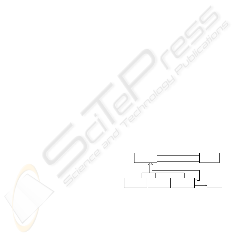
3.1.1 Interaction Points
As the computational specification of ODP, we use
three type of communication modes: signal point for
asynchronous communications, synchronous points
to provide operations and stream points for continu-
ous communications (Figure 1). A field called “kind”
InteractionPoint
+iPKind:IPKind
OperationPoint Operation (from
MOF)
name: String
+ implements
UgatzeComponent
1
+informationPoints
0..*
+component
1
+controlPoints
0..*
+component
SignalPoint StreamPoint
Figure 1: Interface of components
(Figure 1) is used to qualify Interaction points. In-
formation points, IIP (Input Information Point) and
OIP (Output Information Point) are dedicated to the
data flow. SEP(Signal Emission Point) and SRP (Sig-
nal Rececption Point) are dedicated to the control
flow. Control points are sharing the same hierarchi-
cal model as information points, expect from con-
tinuous data flow: control primitive can be carried
by message or signals point, and control operations
as life cycle operations or mobility can be carried
ICEIS 2004 - DATABASES AND INFORMATION SYSTEMS INTEGRATION
596

by operation points. Those MOF concepts are con-
strained by a set of well formed rules. Those OCL
(Object constraint Language) statements come with
the “Ugatze::Component” package and express rules
between these concepts.
3.2 Integration devices: Interaction
ViewPoint
The “Interaction” viewpoint defines all the integra-
tion devices that the reuse architecture provides. This
metamodel is separated from the componential view-
point, because it aims different concerns: design for
reuse and design by reuse. The integration of the
components is based on the interactions points of
their interfaces (see section 3.1). In addition, inte-
gration rests on various interactions types: data, con-
trol and mixed interactions. The MOF package called
”Ugatze::Interaction”, relates to the formalisation of
these interactions. It contains the definitions of all
types of Interaction.
3.2.1 Integration mechanisms
From its most abstract form, the interaction connects
different kind of interaction points. For example, the
direct data interaction is a direct connection between a
OIP and a IIP, its communication mode is given by the
type of interaction points it connects. The concept of
direct “predefined” “Interaction” is similar to the con-
cept of “Binding Object” in the Computational View-
point of RM-ODP. In addition to these predefined in-
teractions, we allow the designer to define ”ad hoc”
interactions. There is three kind of “ad hoc interac-
tions”: data, control and mixed one.
3.2.2 Well formed rules
The well formed rules are used in this package to
build interactions. By example, the pre-defined direct
interactions can be built when the signature of con-
nected interaction points are compatibles, and such a
pre-defined control interaction only connects interac-
tion points whose “kind” is “control point”. More-
over, a “data ad hoc interaction” is defined by a rule
concerning the “kind” of interaction points it con-
nects. All those checks are done by OCL rules.
3.3 Middleware Origin Viewpoint
This Viewpoint, defined by the “Ugatze::Origin”
Package contains the implementation properties of
each legacy application, defining system origin of the
component. Its goal is to allow transformation tools
to generate or reuse the interoperability bridges.
3.4 Integration process
The reuse process we propose is “Architecture Cen-
tred”, it is composed by several transformation and
developpment steps, performed on an graph interac-
tions, and following the separation of concerns.
3.4.1 Application Architecture stage
The Application Achitecture process consists on
building an interaction graph, to perform the integra-
tion on design level. This stage exploits the com-
ponent interface viewpoint and the integration view-
point to provide a platform independant model (PIM)
of the component based distributed application. This
graph represents an interconnection of heterogeneous
components which interact thanks to data or con-
trol interactions, and use several predefined integra-
tion tools as mailbox or shared resources. ASIMIL
Project is a practical application of the integration
process. ASIMIL application graph is built from
ASIMIL components and Ugatze interactions. The
component MAS (Multi Agent System) is intended to
deliver a diagnosis on the behaviour of a learner who
is piloting a flight simulator, the PFC (Procedure Fol-
low Up Component) plays the role of supervisor of
this learner during the flight procedure. The reader
will be able to refer to ((Aniort
´
e and Seyler, 2002))
to have a more precise sight of the project and our
proposals relating to it.
Implementation stage is split into two sub activi-
ties, and can be managed by two roles: a specialist of
M2M inteoperability, and a classical component de-
velopper.
3.4.2 M2M Interaction Integration stage
M2M Interaction Integration stage essentially ex-
ploits the midlleware origin viewpoint. This stage
determines the architecture of interoperability bridges
according to the run time environment of the compo-
nents. The PIM is used to determine the sub graphs
constituted by middleware origins and communica-
tion modes. The graph let appears integration points,
shown by the intersection of each sub graph, and ac-
cording to the communication mode: synchronous
communication channel, or publish/subscribe one in a
CORBA/EJB interoperability bridge, GIOP or adhoc
Corba bridges. In this stage, pre-defined interaction
devices (as mail box, shared resource), and “ad hoc”
interactions are considered as classical components.
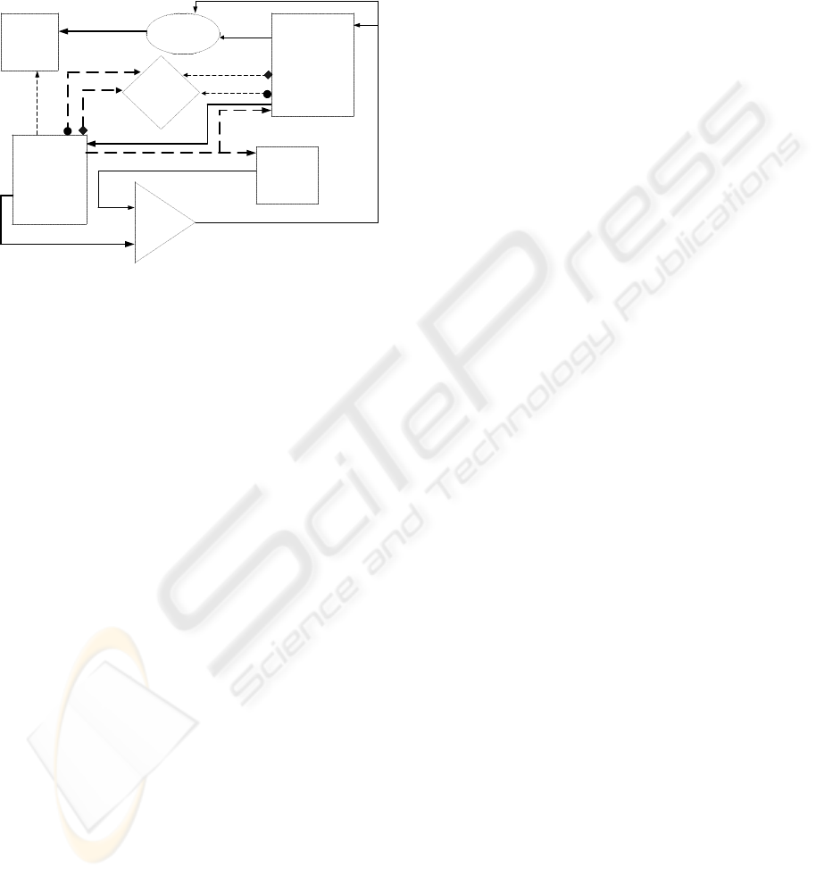
In Figure 2, this view let appear six M2M interactions
between two different run time environments.
3.4.3 Interaction Implementation stage
The Interaction Implementation stage concerns the
implementation or reuse of tools proposed by the plat-
MODEL BASED MIDDLEWARE INTEGRATION
597
form, and of the interactions introduced: by the ar-
chitecture application view: ad’hoc, data, or control
interactions. This development stage exploits a map-
ping of the application model in a given developpment
environment, without any concern on the interoper-
ability problems.
Window
corba
Figure 2: M2M Interactions view of ASIMIL Architecture
4 CONCLUSION
Our main proposal is a model driven integration pro-
cess, which aims to treat middleware to middleware
(M2M) interoperability on multiple abstraction lev-
els: from design to implementation. This process
uses a componential metamodel called “Ugatze”, con-
stituted of several packages allowing a separation of
concerns. This component metamodel allows an in-
tegration for multiple communication modes, and ex-
ploits several interoperability standards as GIOP. This
process is completed by an integration tool, built with
the help of well known OMG’s modelling standards,
on standards Computational concepts, and results to
operational integrations. A first operationnal experi-
ments have been done on an Europeen Project called
Aero user friendly SIMulation based dIstant Learning
(ASIMIL). The work in this projects was to integrate
legacy Applications to provide an e-learning applica-
tion composed of heterogeneous and distributed com-
ponents, this integration has been done by a Ugatze
Component with a Corba/Java event based bridge and
a CORBA based Buid’in Interaction.
REFERENCES
Aniort
´
e, P. and Seyler, F. (2002). A component model
to build a distributed software architecture. In
The 2nd International Conference on Information
Systems and Engineering ISE 2002, volume 34
of Simulation Series, pages 149–154, San Diego.
www.iutbayonne.univ-pau.fr/ seyler/ISE2002.ps.
Cauvet, C. (1999). La rutilisation dans l’ingnierie des
systmes d’information. Herm
`
es Science Publications.
in french.
Dery, A-M.and Blay-Fornarino, M., Moisan, S., Arcier, B.,
and Mule, L. (2001). Distributed access knowledge-
based system: Reified interaction service for trace
and control. In 3rd International Symposium on Dis-
tributed Objects & Applications, DOA’01, pages 76–
84, Rome, Italy.
HCSS (2001). Hcss research needs : a white paper. Tech-
nical report, IWG/IT R& D, White House National
Science and Technology Concil.
Marca, D. and McGowan, C. (1987). Sadt – structured anal-
ysis and design technics. McGraw-Hill.
Marvie, R. (2002). S
´
eparation des pr
´
eoccupations et m
´
eta-
mod
´
elisation pour environnements de manipulation
d’architectures logicielles
´
a base de composants. PhD
thesis, Laboratoire informatique de Lille.
Medvidovic, N. and Taylor, R. N. (1997). A framework
for classifying and comparing architecture descrip-
tion languages. In Jazayeri, M. and Schauer, H., edi-
tors, Proceedings of the Sixth European Software En-
gineering Conference (ESEC/FSE 97), pages 60–76.
Springer–Verlag.
Meurisse, T. and Briot, J. (2001). Une approche base de
composants pour la conception d’agent. Technique et
Science Informatique, 20(4/2001):567–586. in french.
Miller, J. and al (2001). Model driven architecture. Tech-
nical report, Object Managment Group(OMG). Doc-
ument number ormsc/2001-01-10.
OMG (1999). Corba/iiop- 2.3.1 specification. Technical
report, Object Managment Group.
OMG (2002a). Uml profile and interchange models for
enterprise application integration (eai) specification.
Technical report, Object Managment Group. final
adopted specification.
OMG (2002b). Uml profile for enterprise distributed object
computing (edoc). Technical report, Object Manag-
ment Group.
Peschansky, F. and al (2000). Les composants logiciels :
Evolution technologique ou nouveau paradigme? In
Conf
´
erence OCM, pages 53–65. in french.
Putman, J. (2001). Architecting with RM-ODP. Prentice
Hall.
Singh, N. (1998). Unifying heterogeneous information
models. Communications of the ACM, 41(5):37–44.
Soley, R. (2000). Model driven architecture. Technical re-
port, Object Managment Group(OMG). White Paper
Draft 3.2 (www.omg.org/mda).
ICEIS 2004 - DATABASES AND INFORMATION SYSTEMS INTEGRATION
598
