
FEATURE MATCHING IN MODEL-BASED SOFTWARE
ENGINEERING
Alar Raabe
Department of Computer Engineering, Tallinn Technical University, Ehitajate tee 5, 19086 Tallinn, Estonia
Keywords: Model-based development, model-driven architecture (MDA), domain modeling, feature models, software
engineering
Abstract: There is a growing need to reduce the cycle of business information systems development and make it
independent of underlying technologies. Model-driven synthesis of software offers solutions to these
problems. This article describes a method for synthesizing business software implementations from
technology independent business models. The synthesis of business software implementation performed in
two steps, is based on establishing a common feature space for problem and solution domains. In the first
step, a solution domain and a software architecture style are selected by matching the explicitly required
features of a given software system, and implicitly required features of a given problem domain to the
features provided by the solution domain and the architectural style. In the second step, all the elements of a
given business analysis model are transformed into elements or configurations in the selected solution
domain according to the selected architectural style, by matching their required features to the features
provided by the elements and configurations of the selected solution domain. In both steps it is possible to
define cost functions for selecting between different alternatives which provide the same features. The
differences of our method are the separate step of solution domain analysis during the software process,
which produces the feature model of the solution domain, and usage of common feature space to select the
solution domain, the architectural style and specific implementations.
1 INTRODUCTION
Today business processes become increasingly
dependent on the software, and must change rapidly
in response to market changes. Initial results from
software development should be delivered with a
very short delay and have to be deployable with
minimal costs. When the business volume grows, or
the business processes change, supporting software
systems must be able to grow and change along,
without impeding the business process and without a
major reimplementation effort. To achieve different
non-functional requirements (e.g. quality of service)
needed for business information systems, different
implementation technologies, which themselves are
rapidly evolving, are to be used and combined.
As a result, there is a growing need to shorten the
development cycle of business information systems,
and to achieve its independence of underlying
technologies, which often evolve without offering
backward compatibility. Therefore the main body of
reusable software assets of an enterprise should be
independent of implementation technologies.
These problems are addressed by model-based
approaches to software development, e.g. model-
based software synthesis (Abbott et al., 1993),
model-based development (Mellor, 1995), and
model driven architecture (MDA) (OMG, 2001a). In
the model-based software development, the primary
artifact is a model of the required software system,
which becomes the source of the specific
implementation of a given software system created
through synthesis or generation.
We treat the development of business
information systems as similar to domain-oriented
application development technologies (SEI, 2002
and Honeywell, 1996), where business, in general, is
treated as a large general domain containing several
more specific domains (business areas), which refer
to common elements from the general business
domain.
In this article we describe a method that is
applicable to synthesizing business software
implementations from technology independent
business models.
Our method is based on establishing a common
163
Raabe A. (2004).
FEATURE MATCHING IN MODEL-BASED SOFTWARE ENGINEERING.
In Proceedings of the Sixth International Conference on Enterprise Information Systems, pages 163-172
DOI: 10.5220/0002618201630172
Copyright
c
SciTePress

feature space for problem and solution domains for
the business information systems and using the
features of problem domain elements for
synthesizing the implementation from the solution
domain elements.
The problems analyzed in this article are:
• existence and contents of a common feature
space for problem and solution domains,
• a method for the synthesis of implementation
from analysis models based on the common
features of problem and solution domain
elements.
Presented method requires a separate step of
solution domain analysis during the software
engineering process described in (Raabe, 2003).
During both the problem domain and solution
domain analysis, the previously described
techniques of using the extended meta-models
(Raabe, 2002) are used to incorporate feature
models.
The rest of this paper is organized as follows.
Section 2 analyzes briefly the usage of models in
software engineering, section 3 describes the feature
-based methods suitable for solution domain
analysis, and section 4 proposes a feature matching
technique for implementation synthesis from
analysis models.
2 USAGE OF MODELS IN
SOFTWARE ENGINEERING
In the software engineering process, models are
traditionally used for documentation purposes and
in certain cases as source artifacts for automatic
derivation (e.g. generation) of other artifacts.
Models as documentation could be used to
document results of analysis, design, or
implementation phases of software projects.
Models as source artifacts could be used to
represent results of analysis (e.g. description of a
problem statement), or to represent results of design
(e.g. high level description of a solution). In both
cases, models are a source for either a compilation
or generation process where new dependent artifacts
are created or for the interpretation or execution
process, where the models directly drive the
implementation.
2.1 Definitions
We will use the following definitions from UML:
• a domain is an area of knowledge or activity
characterized by a set of concepts and
terminology understood by practitioners in
that area (OMG, 2001b);
• a model is a more or less complete
abstraction of a system from a particular
viewpoint (Rumbaugh, Jacobson & Booch,
1999).
We assume that domains may themselves
contain more specific sub-domains, i.e. there can
exist a generalization relationship between domains
(Simos et al., 1996). Based on this generalization
relationship, domains form a taxonomic hierarchy.
We extend the meaning of the model to represent
not only abstractions of physical systems (OMG,
2001b) but also abstractions of logical systems.
We will use the following definition from
Organization Domain Modeling (ODM) (Simos et
al., 1996):
• a feature is a distinguishable characteristic of
a concept (e.g. system, component) that is
relevant to some stakeholder of this concept.
Features of a given software system are
organized into feature model(s).
Additionally, we introduce the following
definitions:
• a domain model is a body of knowledge in a
given domain represented in a given
modeling language (e.g. UML);
• a problem domain of a software system is a
domain which is the context for
requirements of that software system;
• a solution domain of a software system is a
domain which describes the implementation
technology of that software system;
• an analysis model is a model of a software
system which contains elements from the
relevant problem domain models and is a
combination and specialization of relevant
problem domain models specified by the set
of functional requirements for a given
software;
• an implementation model is a model of
specific implementation of some software
system which contains elements from the
relevant solution domain models and a
combination and specialization of relevant
solution domain models specified by the set
of non-functional requirements for a given
software system;
• a feature space is a set of features, which are
used in a given set of feature models;
• a configuration (or topology) is a set of
interconnected domain elements or concepts,
which collectively provide a certain set of
features.
We use the term implementation model instead
of the design model to stress that this model
represents not only the logical level of design, but
the design of the software system for the specific
ICEIS 2004 - INFORMATION SYSTEMS ANALYSIS AND SPECIFICATION
164
combination of solution domains – a specific
implementation.
2.2 Model-based Software
Engineering Methods
Model-based software engineering covers software
development methods, where models are the main
artifacts and some or all other artifacts are derived
from the models.
Model-based software engineering was first
taken into use in application domains where the
correctness and reliability of software were very
important (i.e. in real-time and embedded systems).
In these cases, extensive usage of models during
analysis and design was inevitable due to the
complexity of the domain and high-level quality
requirements for resulting systems. Existence of up-
to-date models and the need to retain properties of
models in the implementation facilitated their use as
a source for other artifacts during the software
engineering process.
Examples of this approach to the engineering of
embedded and real-time software are Model-
Integrated Computing (MIC) developed in
Vanderbilt University ISIS (Abbott et al., 1993) and
Model-Based Development (MBD) developed by
Shlaer and Mellor (Mellor, 1995).
Later, model-based software engineering was
also taken into use in other application domains like:
• for generative programming with
reusable components – GenVoca developed
in Texas University (Batory and O'Malley,
1992),
• for the development and configuration
of members of software system families (i.e.
product line architectures) – Family-Oriented
Abstraction, Specification, and Translation
(FAST) developed in AT&T (Weiss, 1996),
and
• for the integration and interoperability
of distributed systems – Model-Driven
Architecture (MDA) proposed by OMG
(OMG, 2001a).
In the traditional approach to model-based
software engineering, implementation can be
derived either from the description of very high-
level solution to the problem or from the problem
description itself.
In the first case, an analyst creates an analysis
model which describes the problem, based on the
problem domain knowledge. Next a designer, based
on the solution domain knowledge, creates a design
model that will be automatically transformed to the
actual implementation of the system.
In the second case, the analysis model itself is
directly transformed into an implementation.
These cases both need previously prepared
description of transformation, which incorporates
the knowledge of problem and solution domains.
This description of transformation will then be
reusable for several problem descriptions which all
belong to the same problem domain.
In the present approaches to model-based
software engineering, the knowledge about the
problem and solution domains is implicit (i.e.
embedded into the transformation description) and
the transformation from the problem domain into the
solution domain often depends on the chosen
transformation technology.
While model-based approaches apply the model-
based software engineering paradigm to the
development of actual software, the development of
transformations is usually following the old software
engineering paradigms.
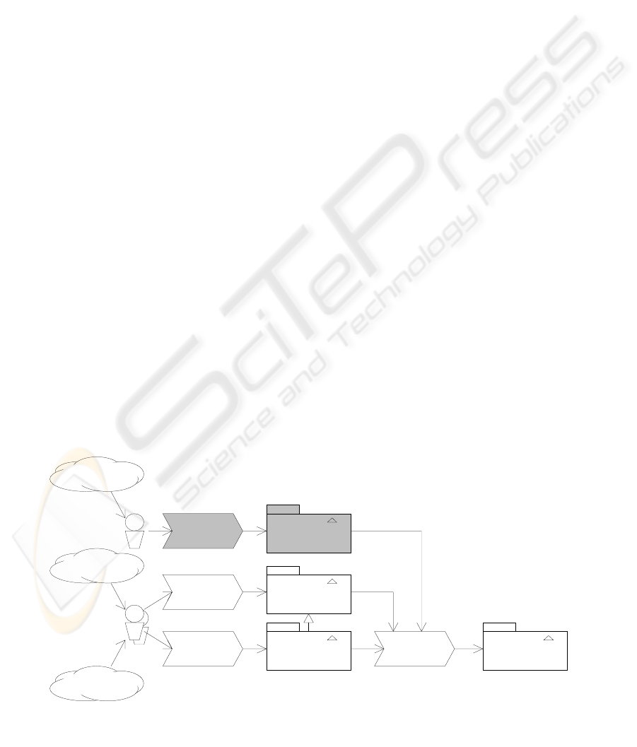
Synthesis of
Specific system
Solution domain
Analysis
Problem domain
Analysis of
Specific system Analysis Model Implementation Model
(Specific software)
Problem domain
System requirements
Analysts
knowledge
Solution domain
knowledge
Analyst
Analysis Model
Analysis Model
Problem Domain
Solution Domain
Analysis
Figure 1: Model-based software engineering process with a separate solution domain analysis step
FEATURE MATCHING IN MODEL-BASED SOFTWARE ENGINEERING
165
2.3 Proposed Model-based Software
Engineering Method
In (Raabe, 2003), we proposed solution domain
analysis as an additional step during the software
process (as shown in Fig. 1). Introducing this
additional step will produce a solution domain
model and will allow us to use formalized results of
problem domain analysis and solution domain
analysis as a basis for deriving the description of
transformation from the analysis model to the
implementation model.
3 DOMAIN ANALYSIS
Domain engineering (SEI, 2002) encompasses
domain analysis, domain design, and domain
implementation. Domain analysis contains the
following activities:
• domain scoping, where relevant domain with
its sub-domains will be selected and the
main area of focus will be defined, and
• domain modeling, where relevant domain
information is collected and integrated into a
coherent domain model.
Domain model defines the scope (i.e. boundary
conditions) of the domain, elements or concepts that
constitute the domain (i.e. domain knowledge),
generic and specific features of elements and
configurations, functionality and behavior.
According to the different domain engineering
approaches, there are several different domain
analysis methods (Czarnecki and Eisenecker, 2000).
3.1 Feature-oriented domain analysis
Feature modeling, also known as feature analysis, is
the activity of modeling the common and the
variable properties of concepts and their
interdependencies.
Feature-oriented domain analysis methods
describe the characteristics of a problem and the
required characteristics of a solution independently
of their structure.
Examples of feature-oriented domain analysis
methods are:
• Feature-Oriented Domain Analysis (FODA)
from SEI (Kang et al., 1990), which became
a part of their MBSE framework (SEI);
• Feature-Oriented Reuse Method (FORM)
developed by K. Kang (Kang, 1998);
• Domain Engineering Method for Reusable
Algorithmic Libraries (DEMRAL) by
Czarnecki and Eisenecker (Czarnecki and
Eisenecker, 2000).
Feature model consists of the following
elements:
• concepts – any elements and structures of the
domain of interest and
• features – qualitative properties of the
concepts.
A feature model represents feature types and
definitions, hierarchical decomposition of features,
composition rules (i.e. dependencies between
concepts) and rationale for features. It consists of a
feature diagram and additional information.
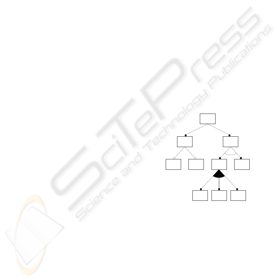
Feature diagram is a tree-like diagram, where the
root node represents a concept and other nodes
represent features of this concept and sub-features of
features. An example of a feature diagram is shown
in Fig. 2.
From the composition point of view, the
following feature types are most commonly used in
feature models:
• mandatory features (e.g. f
1
, f
2
, f
5
, f
6
, f
7
, f
8
, f
9
),
• optional features (e.g. f
3
, f
4
),
• alternative features (e.g. f
5
, f
6
), and
• or-features (e.g. f
7
, f
8
, f
9
).
Composition rules between features are
constraints for composing features for instances of
concepts (e.g. “requires”, “excludes”).
From the domain point of view, it is possible to
describe different feature classes.
FODA (Kang et al., 1990) distinguishes between
context features (non-functional characteristics of
application), operational features (application
functions), and representation features (interface
functions).
FORM (Kang, 1998) distinguishes between
capability features (further divided into functional
and non-functional features), operating environment
features, domain technology features, and
implementation technique features.
DEMRAL (Czarnecki and Eisenecker, 2000)
distinguishes between the following feature classes:
C
f
1
f
2
f
3
f
4
f
5
f
6
f
7
f
9
f
8
Figure 2: Example of a feature diagram
ICEIS 2004 - INFORMATION SYSTEMS ANALYSIS AND SPECIFICATION
166

• features for all the concepts: attributes, data
structures, operations, error handling,
memory management, synchronization,
persistence, perspectives, and subjectivity,
and
• features for container-like concepts: element
type, indexing, and structure.
Additionally, domain features in DEMRAL are
annotated with the priorities representing the
typicality and importance of a given feature.
During the domain analysis, the following
models are created:
• traditional models for
° static structures (e.g. class models, object
models),
° functionality (e.g. use-case models,
scenario models), and
° interactions or behavior (e.g. sequence
models, collaboration models);
• feature models for functional and non-
functional features.
Characteristic configurations of a given domain
are identified during the domain analysis before the
feature modeling and are represented as models of
the static structures.
A feature set of a configuration might be larger
than the sum of feature sets of all the concepts in the
configuration.
Similarly to configurations, it is also possible to
attach a set of non-functional features to the entire
domain.
3.2 Problem Domain Analysis
Taking the insurance domain as an example of a
problem domain, we will study the feature model of
some concepts from this domain. Let us take as an
example a concept Policy which represents an
insurance agreement between an insurer and a policy
holder. In the insurance domain model, this concept
represents an independent business entity. As such,
it has the following features:
• characteristic to the problem domain
(insurance):
° attributes (e.g. policy number, policy
holder);
° processing states (e.g. quote, offer);
° attached business rules (e.g. validity and
consistency conditions);
° business processes attached (e.g. offering,
renewal);
° services (e.g. computing the price, change
of state);
• generic – independent of the problem
domain:
° it has identity;
° it exists independently of other concepts
in a given problem domain;
° it has a state represented by the attributes;
° it is transactional;
° it is persistent and searchable;
° it is viewable and modifiable.
Another example is a concept Renewal, which
represents a process of renewing some of the
characteristics of an insurance agreement. In the
insurance domain model, this concept represents a
business process. As such it has the following
features:
• characteristic to the problem domain
(insurance):
° parameters (e.g. target date);
° attached business rules (e.g. precondition
and post condition);
° it operates on other specific elements of a
problem domain (e.g. policy);
• generic – independent of the problem
domain:
° it has no identity;
° it has no state represented by the
attributes;
° it is transient.
These examples show that apart from features
which are domain dependent, elements of a problem
domain have certain generic features.
3.3 Solution Domain Analysis
Taking J2EE (Singh et al., 2002) as an example of a
solution domain, we will study the feature model of
some concepts from J2EE. Let us take as an example
a concept EntityBean, which represents persistent
data. As such, it has the following features:
• characteristic to the solution domain (J2EE):
° attributes (e.g. context, primary key,
handle);
° processing states (e.g. active, passive);
° attached rules (e.g. constraints on the
state);
° attached processes (e.g. passivation,
activation, etc.);
° services (e.g. create, find);
• generic – independent of the solution domain:
FEATURE MATCHING IN MODEL-BASED SOFTWARE ENGINEERING
167
° it has identity;
° it exists independently of other concepts;
° it has a state represented by the attributes;
° it is transactional;
° it is persistent and searchable.
Another example is a concept Stateless
SessionBean, which represents a functional service.
As such, it has the following features:
• characteristic to the solution domain (J2EE):
° parameters (e.g. context, handle);
° processing states (e.g. active, passive);
° attached rules (e.g. constraints on the
state);
° attached processes (e.g. passivation,
activation);
• generic – independent of the solution domain:
° it has no identity;
° it has no state represented by attributes;
° it is transient;
° it is scalable.
These examples show that apart from the
features, which are domain dependent, elements of a
solution domain and elements of problem domain
have similar generic features.
These generic features, which are common for
the problem and solution domain elements, stem
from the generic requirements toward the software
systems and describe various domain independent
qualities of these elements. In nature, these generic
features may be either functional or non-functional.
Analyzing J2EE as a solution domain, we see
that certain generic features, which we identified in
the problem domain example, require a
configuration of concepts which will collectively
provide them.
For example, to achieve the generic features of
persistence, searchability, viewability, and
modifiability in J2EE, we would have to construct a
configuration consisting of EntityBean, some
database domain concepts (e.g. table), and some user
interface concepts (e.g. JSP).
4 FEATURE MATCHING
If the results of solution domain analysis are
formalized into the models following the same
analysis paradigm as the problem domain analysis, it
will be possible to develop automatic synthesis of
transformation rules. These rules will be
transforming the analysis model of a system in the
problem domain into an implementation model of
the same system in the solution domain, producing
the implementation of the specified system.
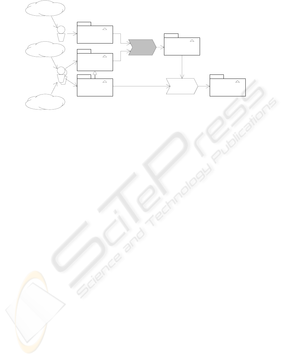
If this automatic synthesis of transformation
rules is based on the features of the solution domain
and problem domain elements, we call it feature
matching (shown in Fig. 3.).
In the proposed method, synthesis of business
software implementation from the technology
independent business analysis model is performed in
two steps.
First, a solution domain and software
architecture style are selected by matching the
explicitly required features of a given software
system and implicitly required features of a given
problem domain to the features provided by the
software architecture style.
Next, all elements of a given business analysis
model are transformed into elements or sets of
interconnected elements of the selected architecture
style, by matching their required features to the
features provided by the elements of the selected
architecture style. During this step, the common
feature model drives the design of software
implementation.
Analysis Model Implementation Model
(Specific software)
Problem domain
System requirements
Analysts
knowledge
Solution domain
knowledge
Transformation
Model
Analyst
Analysis Model
Analysis Model
Problem Domain
Solution Domain
Feature
Matching
Synthesis of
Specific system
Figure 3: Model-based software engineering process with feature matching
ICEIS 2004 - INFORMATION SYSTEMS ANALYSIS AND SPECIFICATION
168
In both steps it is possible to define the cost
functions for selecting between different alternatives
that provide the same features.
4.1 Common Feature Space
In the previous study of applying feature modeling
to problem domain analysis and solution domain
analysis, we discovered that there exists a set of
features which is common to both domains.
Elements of both domains:
• have the following functional features:
° may have or may not have identity,
° can be independent in their existence or
dependent on other elements,
° may have or may not have a state
represented by the attributes (be stateful
or stateless),
° can be transient or persistent,
° in case they are persistent, can be
searchable,
° can be viewable,
° in case they are viewable, can be
modifiable,
° have asynchronous or synchronous
behavior,
• have the following non-functional features:
° efficiency (in terms of speed or space),
° scalability,
° modifiability,
° portability.
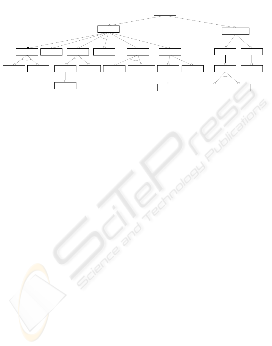
These common features form a common feature
space (Fig. 4), which is a basis to the synthesis of the
implementation of an actual system from a problem
description. This synthesis is a process of finding
mapping between the model in the problem domain
and the model in the solution domain, guided by the
common features of model elements.
4.2 Solution Domain Selection
Usually, in the software engineering process, there
are several different implementation technologies
and architectural styles (Shaw and Garlan, 1996)
available to choose from. In principle, it should be
possible to make a decision on the architectural style
and implementation technology independently, but
often the implementation technology prescribes
certain architectural styles, which are better
supported than others.
In the process of synthesizing implementation
from the model in the problem domain, the first task
is to select the suitable solution domain. This will be
based mainly on non-functional features of solution
domains (e.g. scalability, modifiability). At that
stage, it might happen that one solution domain does
not provide all the required features. In this case, it
would be necessary to combine several solution
domains. This combination of solution domains (e.g.
Java language combined with certain RDBMS to
provide persistence) forms a new solution domain
that is applicable to a given problem.
Examples of selecting architectural style:
• a suitable architectural style for data-entry
application is “central repository”, a front-
end application with the back-end data
storage (e.g. RDBMS);
• a suitable architectural style for signal
processing application is “pipes and filters”,
where “filters” implement transformations on
signals and are connected with “pipes”;
• a suitable architectural style for decision
support system is “blackboard”, where
relatively autonomous agents are cooperating
via common model of situation.
Concept
Functional
Identity Stateful Stateless
Independent Dependent TransientPersistent
Searchable
Viewable
Modifiable
Synchronous Asynchronous
Non-functional
Efficient
Memory Speed
Scalable Modifiable
Portable
Behavior Presentable
Printable
Existence
Figure 4: Common feature space
FEATURE MATCHING IN MODEL-BASED SOFTWARE ENGINEERING
169

4.3 Implementation Synthesis
The next step in the feature matching, when the
solution domain is selected, is actual implementation
synthesis. During this process, for every element of
the problem domain model, a suitable element or a
suitable configuration of elements of the solution
domain model is selected. The result is a mapping
from the problem domain model to the solution
domain model (i.e. implementation). Suitability of
the solution domain element(s) for a given problem
domain model element is decided by their
corresponding features.
Descriptions of concepts (or domain elements)
are given by the sets of their features:
C = F = {f
i
}
and sets of features of configurations of concepts
are the unions of all the feature sets of elements in
the configuration:
{C
1
, ..., C
n
} = F
1
∪ ... ∪ F
n
We represent the mapping between the concepts
of the problem domain and those of the solution
domain:
ƒ : {C
P
}
→
{C
S
}
or simply:
{C
P
}
→
{C
S
}
We reduce finding a suitable configuration in the
solution domain for the generic case to different
specific cases, which cover all situations.
The first case is trivial – when the feature set of a
problem domain element is a subset of the feature
set of a certain solution domain element, then the
problem domain element is mapped directly to this
solution domain element:
F
P
⊆ F
S
⇒ {C
P
}
→
{C
S
}
The second case – when the feature set of a
problem domain element is a subset of the union of
feature sets of a configuration of solution domain
elements, then the problem domain element is
mapped directly to this configuration of the solution
domain elements:
F
P
⊆ F
S
1
∪ … ∪ F
S
m
⇒ {C
P
} → {C
S
1
, … , C
S
m
}
The third case – when there exists a
configuration of problem space elements consisting
of n elements, then if the union of feature sets of
these elements is a subset of the feature set of a
certain solution domain element, the given
configuration of problem domain elements is
mapped to this solution domain element:
F
P
1
∪ … ∪ F
P
n
⊆ F
S
⇒ {C
P
1
, … , C
P
n
} → {C
S
}
The last case is the most complex and describes
also the generic case – when there exists a
configuration of problem space elements consisting
of n elements, then if the union of feature sets of
these elements is a subset of union of feature sets of
a certain configuration of solution domain elements,
the given configuration of the problem domain
elements is mapped to this configuration of solution
domain elements:
F
P
1
∪ ... ∪ F
P
n
⊆ F
S
1
∪ ... ∪ F
S
m
⇒
{C
P
1
, ..., C
P
n
}
→
{C
S
1
, ..., C
S
m
}
This step is driven by the structure of the
problem domain model and the analysis model.
4.4 Selecting Between Alternatives
Different solution domains usually have different
non-functional features or quality attributes (Bass,
Clements & Kazman, 1998). These non-functional
features could be divided to run-time features (e.g.
performance, security, availability, usability) and
maintenance features (e.g. modifiability, portability,
reusability, integrability, testability). The
combination of non-functional features corresponds
to a certain set of business goals (e.g. time to
market, cost, projected lifetime, market share,
rollout schedule).
The non-functional requirements connected to
the problem specification can be used to choose
between possible solution domains and usage styles
of the given solution domain elements (e.g. software
architecture style).
Inside a solution domain there may exist many
configurations of solution domain elements, which
can be used to implement the same functional or non
-functional requirements. There feature matching
algorithm can use different strategies of choosing
between elements and configurations of the solution
domain.
There can be alternatives between the elements
or configurations of the solution space, which offer
similar feature sets:
F
P
⊆ F
S
1
& F
P
⊆ F
S
2
In this case, during the feature matching, it is
possible to use different strategies to make the
decision between alternatives. Possible feature
ICEIS 2004 - INFORMATION SYSTEMS ANALYSIS AND SPECIFICATION
170

matching strategies are maximal, minimal, or
optimal.
The maximal strategy, where the solution
domain element or configuration is selected, if it
provides most additional features for implementing a
given problem domain element:
|F
S
1
\ F
P
| < |F
S
2
\ F
P
| ⇒ {C
P
} → {C
S
2
}
The minimal strategy, where the solution domain
element or configuration is selected, if it provides
least additional features for implementing a given
problem domain element:
|F
S
1
\ F
P
| < |F
S
2
\ F
P
| ⇒ {C
P
} → {C
S
1
}
The optimal strategy, where a solution domain
element or a configuration is selected, based on the
cost function:
cost(F
S
1
) < cost(F
S
2
) ⇒ {C
P
} → {C
S
1
}
where the cost function cost(F) is based on non-
functional features of C
S
i
.
For example, if we take into account the
scalability requirements in the case described above,
we would select the configuration built around the
SessionBean instead of EntityBean for the concept
policy.
When selecting a suitable solution, the domain
can be viewed as global optimization, selecting
suitable configurations in the selected solution
domain can be viewed as local optimization.
5 RELATED WORK
A similar problem has been analyzed in the context
of domain engineering approach in SEI (Peterson
and Stanley, 1994). Peterson and Stanley have
studied mapping of the domain model to a generic
design. In their work, they presented mapping from
the domain analysis results presented in FODA into
the predefined architecture (OCA – Object
Connection Architecture) by architecture elements.
Another similar technique is presented in the
Feature-Oriented Reuse Method (FORM) developed
by K. C. Kang (Kang, 1998). In this method, also a
feature space (result form FODA) is mapped into a
predefined artifact space (an architecture) by using
kinds of features identified in the feature modeling.
Both of these methods allow mapping of the
problem domain results only into predefined
architecture.
The difference of our approach from these two
approaches is that we allow synthesis of
implementations in different, not predefined solution
domains.
Selection of the architectural style, based on
reasoning about the quality attributes of architectural
styles is dealt with in the Attribute-Based
Architecture Styles (ABAS) method (Bass,
Clements & Kazman, 1998).
Lately the MDA initiative from OMG (OMG,
2001a) has been establishing modeling standards
needed to develop supporting tools for mapping
platform independent models (PIMs) into platform
specific models (PSMs). Techniques and tools
presented in the article are in line with MDA and
useful when the MDA approach is applied to the
development of large-scale business systems.
6 CONCLUSIONS
The difference of our method from other domain
specific and model-based methods is the separate
step of solution domain analysis, which results in a
reusable solution domain model, and using a feature
space that is common to the problem and solution
domains, for selecting the solution domain, the
architecture style, and specific implementations.
We have shown that there exists a common
feature space for both the problem domain and
solution domain elements.
We have presented an algorithm based on this
common feature space for selecting the solution
domain, architectural style, and for synthesizing an
implementation.
We have also shown that it is possible to drive
the solution domain selection and implementation
synthesis algorithm with a suitable cost function.
The presented method allows shorter software
development cycles due to the automation of the
implementation phase, reusability of the problem
domain knowledge (i.e. business analysis models)
with different solution domains (i.e. implementation
technologies), and better usability of solution
domain knowledge. It is applicable to OMG MDA
for transformation or mapping of the platform
independent model (PIM) to platform specific
models (PSMs).
In the future, providers of implementation
technologies (e.g. J2EE) may supply also the models
of their solution domains (incl. feature models),
together with other artifacts of a given
implementation technology. Together with the
development of tools that could synthesize
implementations based on the problem domain
models by using feature matching, this would
dramatically reduce the threshold of using new
implementation technologies for software
FEATURE MATCHING IN MODEL-BASED SOFTWARE ENGINEERING
171

engineering. This would require establishment of a
standard for common feature space, and a standard
for representing feature models.
In our next research steps we will study the
common feature space for consistency and
completeness and solution domain configurations
(e.g. emerging new feature sets during synthesis and
the relationship of solution domain configurations to
design patterns).
ACKNOWLEDGEMENTS
Author wishes to gratefully acknowledge Profit
Software Ltd. (Finland) and the Estonian Science
Foundation for their support (Grant 4721).
Author wishes to thank Riina Putting and Kert
Uutsalu for discussions on the subject and many
useful suggestions for improving this paper.
REFERENCES
Abbott, B., Bapty, T., Biegl, C., Karsai, G., Sztipanovits,
J., 1993, Model-Based Software Synthesis, IEEE
Software, May, 10 (3), 1993, pp.42-52.
Bass, L., Clements, P. and Kazman, R., 1998, Software
Architecture in Practice, Addison-Wesley.
Batory, D. and O'Malley, S., 1992, The design and
implementation of hierarchical software systems with
reusable components, ACM Transactions on Software
Engineering and Methodology, Vol. 1, No. 4, pp. 355-
398.
Czarnecki, K., Eisenecker, U., W., 2000, Generative
Programming, Methods, Tools, and Applications,
Addison-Wesley.
Honeywell, 1996, Domain-Specific Software
Architectures, www.htc.Honeywell.com/projects/dssa
Kang, K. C., Cohen, S. G., Hess, J. A., Novak, W. E.,
Peterson, A. S., 1990, Feature-Oriented Domain
Analysis (FODA) Feasibility Study, SEI CMU,
CMU/SEI-90-TR-021
Kang, K. C., Kim, S., Lee, J., Kim, K., Shin, E., and Huh.,
M., 1998, FORM: A feature-oriented reuse method
with domain-specific reference architectures. Annals
of Software Engineering, Vol. 5, pp. 143-168.
Medvidovic, N., Taylor, R. N., 1997, A Framework for
Classifying and Comparing Architecture Description
Languages, Proceedings of the Sixth European
Software Engineering Conference (ESEC/FSE 97), Ed.
by M. Jazayeri and H. Schauer, Springer Verlag, pp.
60-76.
Mellor, S. J., 1995, Reuse through automation: Model-
Based Development, Object Magazine, September
1995.
OMG, 2001a, Model Driven Architecture, OMG 01-07-01,
ftp.omg.org/pub/docs/ormsc
OMG, 2001b, OMG Unified Modeling Language
Specification Version 1.4, OMG 01-09-67,
ftp.omg.org/pub/docs/formal
Peterson, A. S., Stanley, J. L., 1994, Mapping a Domain
Model and Architecture to a Generic Design, SEI
CMU, CMU/SEI-94-TR-008
Raabe, A., 2002, Techniques of combination of
metamodel extensions, Proceedings of the Estonian
Academy of Sciences, Engineering, 8 (1), 2002, pp. 3-
17.
Raabe, A., 2003, Software Engineering Environment for
Business Information Systems, In Proceedings of
ICEIS 2003, 5th International Conference on
Enterprise Information Systems, Angers, France, 23-
26 April, 2003, Volume 3, pp. 129-137.
Rumbaugh, J., Jacobson, I., and Booch, G., 1999, The
Unified Modeling Language Reference Manual,
Addison-Wesley, Reading, Massachusetts.
SEI, 2002, Domain Engineering: A Model-Based
Approach, www.sei.cmu.edu/domain-engineering
Simos, M., Creps, D., Klinger, C., Levine, L., and
Allemang, D., 1996, Organization Domain Modeling
(ODM) Guidebook, Version 2.0, Technical Report for
STARS, STARS-VC-A025/001/00, June 14, 1996.
Singh, I., Stearns, B., Johnson, M. and the Enterprise
Team, 2002, Designing Enterprise Applications with
the J2EE Platform, Second Edition, Addison-Wesley.
Shaw, M., Garlan, D., 1996, Software Architecture:
Perspectives on an Emerging Discipline, Prentice-
Hall.
Weiss, D., 1996, Family-Oriented Abstraction,
Specification, and Translation The FAST Process,
Keynote talk at Computer Assurance Conference
(COMPASS), 19 June 1996,
www.research.avayalabs.com/user/weiss/pubs/compas
s96.ps
ICEIS 2004 - INFORMATION SYSTEMS ANALYSIS AND SPECIFICATION
172
