
ANALYSIS AND RE-ENGINEERING OF WEB SERVICES
Axel Martens
Humboldt-Universität zu Berlin,
Department of Computer Science
Keywords:
Web services, Business Processes, Analysis, Usability, Petri nets
Abstract:
To an increasing extend software systems are integrated across the borders of individual enterprises. The Web
service approach provides group of technologies to describe components and their composition, based on well
established protocols. Focused on business processes, one Web service implements a local subprocess. A
distributed business processes is implemented by the composition a set of communicating Web services.
At the moment, there are various modeling languages under development to describe the internal structure of
one Web service and the choreography of a set of Web services. Nevertheless, there is a need for methods for
stepwise construction and verification of such components.
This paper abstracts from concrete syntax of any proposed language definition. Instead, we apply Petri nets to
model Web services. Thus, we are able to reason about essential properties, e. g. usability of a Web service –
our notion of a quality criterion. Based on this framework, we present an algorithm to analyze a given Web
service and to transfer a complex process model into a appropriate model of a Web service.
1 INTRODUCTION
In this paper, we focus on the application of Web
service technology to distributed business processes:
One Web service implements a local subprocess.
Thus, we regard a Web services as a stateful sys-
tem. From composition of a set of Web services there
arises a system that implements the distributed busi-
ness processes.
Within this setting, the quality of each single Web
service and the compatibility of a set of Web services
are questions of major interest. In this paper, we de-
fine the notion of usability – our quality criterion of
a Web service and present an algorithm to verify this
property. Based on this analysis, we present an ap-
proach to restructure and simplify a given Web ser-
vice model.
1.1 Web services
A Web service is a self-describing, self-contained
modular application that can be described, published,
located, and invoked over a network, e. g. the World
Wide Web. A Web service performs an encapsulated
function ranging from a simple request-reply to a full
business process.
A Web service has a standardized interface and can
be accessed via well established protocols. Thus, the
Web service approach provides a homogenous layer
to address components upon a heterogenous infras-
tructure.
Instead of one new specific technology, the Web
service approach provides group of closely related,
established and emerging technologies to model, pub-
lish, find and bind Web services – called the Web ser-
vice technology stack (Gottschalk, 2000). This paper
is concerned with the application of Web service ap-
proach towards the area of business processes. Thus,
we focus on the behavior of a Web service, defined by
its internal structure.
1.2 Business Processes
A business process consists of a self-contained set
of causally ordered activities. Each activity performs
a certain functionality, produces and consumes data,
requires or provides resources and is executed man-
ually or automatically. A distributed business pro-
cess consists of local subprocesses that are geographi-
cally distributed and/or organizationally independent.
419
Martens A. (2004).
ANALYSIS AND RE-ENGINEERING OF WEB SERVICES.
In Proceedings of the Sixth International Conference on Enterprise Information Systems, pages 419-426
DOI: 10.5220/0002606804190426
Copyright
c
SciTePress

SOAP /
HTTP
BPEL
XML
WSDL
Behavior
Behavior
C horeog rap hy
C horeog rap hy
D at a
D at a
F u n c t ion s
F u n c t ion s
I n t erf ac e
I n t erf ac e
Behavior
Behavior
C horeog rap hy
C horeog rap hy
D at a
D at a
F u n c t ion s
F u n c t ion s
I n t erf ac e
I n t erf ac e
C om m u n ic at ion
C om m u n ic at ion
Web Service A Web Service B
Figure 1: Business processes and Web services
The communication between these subprocesses (via
a standardized interface) realizes the coordination of
the distributed process. Figure 1 sketches the map-
ping between the business terms and the Web service
technologies.
For each aspect of a distributed business process
the Web service technology stack provides an ade-
quate technology, as shown in Figure 1. The core lay-
ers cover the technical aspects: data are represented
by XML documents, the functionality and the inter-
face are defined by help of the Web service Descrip-
tion Language WSDL and the communication uses
standardized protocols, e. g. the Simple Object Access
Protocol SOAP .
The internal structure of a process and the organi-
zational aspects are covered by the emerging layers.
There are different proposals towards a specification
language. We focus on the Business Process Exe-
cution Language for Web services BPEL4WS (BEA
et al., 2002). In combination with the core layers,
BPEL4WS allows to model a business process pre-
cisely, such that the model can be directly executed
by the middleware. Moreover, an abstract model of
the process can be expressed by help of BPEL4WS,
too. Such an abstract model is published to the reposi-
tory such that a potential service requestor can decide,
whether or not that service is compatible to his own
component.
Although the technological basement is given,
there is a lot of open questions: Do two Web ser-
vices fit together in a way, that the composition yields
a deadlock-free system? – the question of compati-
bility. Can one Web service be exchanged by another
within a composed system without running into prob-
lems? – the question of equivalence. Can we reason
about the quality of one given Web service without
considering the environment it will by used in? In this
paper we present the notion of usability – our quality
criterion of a Web service. This criterion is intuitive
and can be easily proven locally. Moreover, this no-
tion allows to answer the other questions mentioned
above.
1.3 Solution
The current paper is part of larger framework for mod-
eling and analyzing distributed business processes by
help of Web services (Martens, 2004). This frame-
work is based on Petri nets. Petri nets are a well
established method for distributed business processes
(van der Aalst, 1998b; van der Aalst, 1998a). As we
will show, Petri nets are also an adequate modeling
language for Web services.
Based on this formalism, we are able to discuss
and define usability of a Web service – our notion
of a quality criterion, and further properties. Due to
our abstract view on behavior and structure of Web
services, the results presented here can be adopted
easily to every concrete modeling language, e. g.
BPEL4WS (Martens et al., 2004).
The remaining paper is structured as follows: Sec-
tion 2 presents very succinctly our modeling ap-
proach. Section 3 establishes the core section of this
paper: Applied to an example, we present the algo-
rithm to verify usability. Besides the verification of
usability, the algorithm generates useful information
for re-engineering. Section 4 presents our approach.
Finally, Section 5 gives an overview of the methods
that belong to our framework.
2 MODELING
The following section presents our modeling ap-
proach. To deal with the problems of distributed busi-
ness processes in a generic manner, we use Petri nets.
Thus, we give a short introduction to Petri nets and
show how to model a Web service. Afterwards we
deal with the composition of those models and dis-
cuss their essential properties.
2.1 Modeling Web services
A distributed business process comes into existence
because of composition of Web services. Each of
these Web services represents a local subprocess. Fig-
ure 2 shows the model of such two subprocess – the
Web service of a travel agency and the Web service of
a customer.
A business process consists of a self-contained set
of activities which are causally ordered. A Petri net
N = (P, T, F) consists of a set of transitions T
(boxes), a set of places P (ellipses) and a flow rela-
tion F (arcs) (Reisig, 1985). A transition represents
an active element, i. e. an activity (e. g. Get Itinerary).
A place represents a passive element, i. e. a state be-
tween activities, a resource or a message channel (e. g.
Itinerary).
ICEIS 2004 - INFORMATION SYSTEMS ANALYSIS AND SPECIFICATION
420

p2
p3
p4
p5
p6
p7
p8
p0
p1
Module
Route
Planning
Itinerary
Means of
Travel
Selection
Get
Itinerary
Collect
Information
Rough
Planning
Detailed
Planning
Send
Schedule
Change
Plan
Provide
Facilities
Route
Planning
p2
p3
p4
p0
p1
Send
Itinerary
Choose
Facilities
Receive
Schedule
Await
Facilities
Module
Customer
Figure 2: A workflow module and its environment
A Web service consists of internal structures that
realize a local subprocess and an interface to com-
municate with its environment, i. e. other Web ser-
vices. Thus, we model a Web service by help of a
workflow net – a special Petri net, that has two dis-
tinguished places α, ω ∈ P to denote the begin (α)
and the end (ω) of a process (van der Aalst, 1998a) –
supplemented by an interface, i. e. a set of places rep-
resenting directed message channels. Such a model
we call workflow module.
Definition 2.1 (Module).
A finite Petri net M = (P, T, F) is called workflow
module (module for short), iff:
(i) The set of places is divided into three disjoint
sets: internal places P
N
, input places P
I
and
output places P
O
.
(ii) The flow relation is divided into internal flow
F
N
⊆ (P
N
×T)∪(T×P
N
) and communication
flow F
C
⊆ (P
I
× T) ∪ (T × P
O
).
(iii) The net N (M) = (P
N
, T, F
N
) is a workflow
net.
(iv) Non of the transitions is connected both to an
input place and an output place.
?
Figure 2 shows on the right side the workflow mod-
ule of a travel agency. The module is triggered by an
incoming Itinerary. Then the control flow splits into
two concurrent threads. On the left side, an available
Means of travel are offered to the customer and the
service awaits his Selection. Meanwhile, on the right
side, a Rough Planning may happen . The Detailed
Planning requires information from the customer. Fi-
nally, the service sends a Route Planning to the cus-
tomer.
2.2 Composing Web services
A distributed business process is realized by the com-
position of a set of Web services. We will now define
the pairwise composition of workflow modules. Be-
cause this yields another workflow module, recurrent
application of pairwise composition allows us to com-
pose of more than two modules.
Figure 2 shows the module of a travel agency and
the module of a customer. Obviously, both modules
can be composed. As a precondition for composition,
we will define the property of syntactical compatibil-
ity of two modules.
Definition 2.2 (Syntactical compatibility).
Two workflow modules A and B are called syntac-
tically compatible, iff the internal processes of both
modules are disjoint, and each common place is an
output place of one module and an input place of the
other.
?
Two syntactically compatible modules do not need to
have a completely matching interface. They might
even have a completely disjoint interface. In that case,
the reason of composition is at least dubious. When
two modules are composed, the common places are
merged and the dangling input and output places be-
come the new interface. To achieve a correct module
as the result of the composition, we need to add new
components for initialization and termination. For
more illustrating examples see (Martens, 2004).
Definition 2.3 (Composed system).
Let A = (P
a
, T
a
, F
a
) and B = (P
b
, T
b
, F
b
) be two
syntactically compatible modules. Let α
s
, ω
s
/∈ (P
a
∪
P
b
) two new places and t
α
, t
ω
/∈ (T
a
∪ T
b
) two new
transitions. The composed system Π = A ⊕ B is
given by (P
s
, T
s
, F
s
), such that:
• P
s
= P
a
∪ P
b
∪ {α
s
, ω
s
}
• T
s
= T
a
∪ T
b
∪ {t
α
, t
ω
}
• F
s
= F
a
∪ F
b
∪ {(α
s
, t
α
), (t
α
, α
a
), (t
α
, α
b
),
(ω
a
, t
ω
), (ω
b
, t
ω
), (t
ω
, ω
s
)}
If the composed system contains more than one com-
ponents for initialization and termination, the corre-
sponding elements are merged.
?
Syntactically, the result of the composition is again
a workflow module. Hence, recurrent application of
pairwise composition allows us to compose of more
than two modules.
Corollary 2.1 (Composing modules): Whenever A
and B are two syntactically compatible workflow
modules, the composed system Π = A ⊕ B is a
workflow module too.
?
This corollary can be easily proven. We therefore
omit the proof here, it can be found in (Martens,
2004).
ANALYSIS AND RE-ENGINEERING OF WEB SERVICES
421
2.2.1 Usability
This paper focusses on distributed business processes.
The composition of two workflow modules A and B
represents a business process, if the composed system
Π = A ⊕ B has an empty interface, i. e. Π is a
workflow net. In that case, we call A an environment
of B.
If a module U is an environment of M, obviously
M is an environment of U too. Thus, the module
Customer shown in Figure 2 is an environment of the
module Route Planning.
In the real world, the environment of a Web ser-
vice may consist of several other Web services. If we
want to reason about that specific Web service, we
don’t have any assumption on its potential environ-
ment. Thus, without loss of generality, we may con-
sider its environment as one, arbitrary structured Web
service.
Given a workflow module and one environment, it
is possible to reason about the quality of the com-
posed system. The notion of soundness (van der
Aalst, 1998a) is an established quality criterion for
workflow nets. Basically, soundness requires each
initiated process to come to a proper final state. Be-
cause a business process arises from composition of
existing components, we use the slightly different no-
tion of weak soundness. See (Martens, 2004) for a
precise definition.
Obviously, the purpose of a workflow module is to
be composed with an environment such that the re-
sulting system is a proper workflow net, i. e. we re-
quire the resulting workflow net to be weak sound.
Thus, we define usability based on weak soundness.
Definition 2.4 (Usability).
Let M be a workflow module.
(i) An environment U utilizes the module M, iff the
composed system Π = M ⊕ U is weak sound.
(ii) The module M is called usable, iff there exists
at least one environment U, such that U utilizes
M.
?
Concerning this definition, the module Customer uti-
lizes the module Route Planning and vice versa. Thus,
both modules are called usable. The notion of usabil-
ity forms the base to derive further properties, e. g. a
detailed discussion on compatibility can be found in
(Martens, 2003a).
3 ANALYSIS
In the previous section we have introduced the notion
of usability. Further essential properties of Web ser-
vices (e. g. compatibility) can be derived from this no-
tion. The definition of usability itself is based on the
existence of an environment. Thus, we cannot dis-
prove the usability of a given Web service, because
we have to consider all its possible (infinitely many)
environments.
Hence, this section provides a different approach:
We derive an adequate representation of the behavior
of a given Web service – the communication graph.
Illustrated by help of an example, we present the al-
gorithm to decide usability. Besides the verification of
usability, we use the communication graph of a Web
service for re-engineering in Section 4.
3.1 Example
To reason about usability, we first take a look on a
example that is complex enough to reflect some in-
teresting phenomenons, but small enough to be easily
understood. Figure 3 shows this example.
Module
Online
Tickets
Standard
Customer
Collect
Information
Premium
Customer
Collect
Information
p18
p2
p3
p4
p5
p6
p7
p9
p8
p11
p13
p10
p1
p12
p0
p19
Acknowledge
Payment
Receive
Payment
Send Special
Offers
Receive
Order
Login
Receive
Order
Receive
Conditions
Acknowledge
Itinerary
Send
Ticket
Send Business
Terms
Send Special
Offers
Send Discount
Level
p14
p15
p16
p17
t1
t2 t3
t4 t5 t6 t7
t8 t9
t10 t12 t13t11
t14 t15
t16
Name
Conditions
Order
Payment
Acknow-
ledgment
Business
Terms
Discount
Level
Ticket
Special
Offers
Figure 3: Module online tickets
In this paper, a Web service implements a local
business process. Thus, the model of a Web ser-
vice often is derived from an existing business pro-
cess model and the structure of the model therefore
reflects the organization structure within the process.
As we will see later, such a Web service model should
be restructured before publishing.
Figure 3 shows a model of a Web service selling
online tickets. Basically, the workflow module con-
sists of two separated parts. After the module re-
ceives the Name of the customer, an internal decision
is made: either the customer is classified as Standard
Customer or as Premium Customer. In the first case,
only the left part of the module is used, and the right
part otherwise. At the end, both cases are join by
sending the ordered Ticket.
Within each case, there are three independent
threads of control – representing three independent
ICEIS 2004 - INFORMATION SYSTEMS ANALYSIS AND SPECIFICATION
422

departments: the marketing dept. sends Special Of-
fers, the canvassing dept. receives the Order and an-
swers by sending the Business Terms or an Acknowl-
edgment, and the accounts dept. manages the finan-
cial part.
To prove the usability of the workflow module On-
line Tickets, we try to derive an environment that uti-
lizes this module. Consider a customer who claims to
be a Premium Customer. He might send his Name and
waits for the Special Offers. Afterwards he sends his
Conditions and expects the information on his current
Discount Level.
Unfortunately, by some reasons he has lost his sta-
tus and he is classified as a Standard Customer. In
that case, the module ignores the Conditions and waits
for the Order and for Payment. The composed system
of such a customer and the module Online Tickets has
reached a deadlock.
Our first approach to find an utilizing environment
was based on the structure of a given module. Al-
though the module Online Tickets is usable – as we
will see later – this approach went wrong. Hence, our
algorithm to decide the usability is based on the be-
havior of a workflow module.
3.2 The communication graph
A workflow module is a reactive system, it consumes
messages from the environment and produces an-
swers depending on its internal state. The problem
is, an environment has no explicit information on the
internal state of the module. But each environment
does know the structure of the module and can de-
rive some information by considering the communi-
cation towards the module. Thus, an environment has
implicit information. We reflect exactly that kind of
information within a data structure – called the com-
munication graph.
Definition 3.1 (communication graph).
A communication graph (V, H, E) is a directed,
strongly connected, bipartite graph with some re-
quirements:
• There are two kinds of nodes: visible nodes V and
hidden nodes H. Each edge e ∈ E connects two
nodes of different kinds.
• The graph has a definite root node v
0
∈ V, each
leaf is a visible node, too.
• There exists a labeling m = (m
v
, m
e
), such that
m
v
yield an definite set of states for each visible
node and m
e
yields a bag of messages to each edge.
?
For the precise, mathematical definition see (Martens,
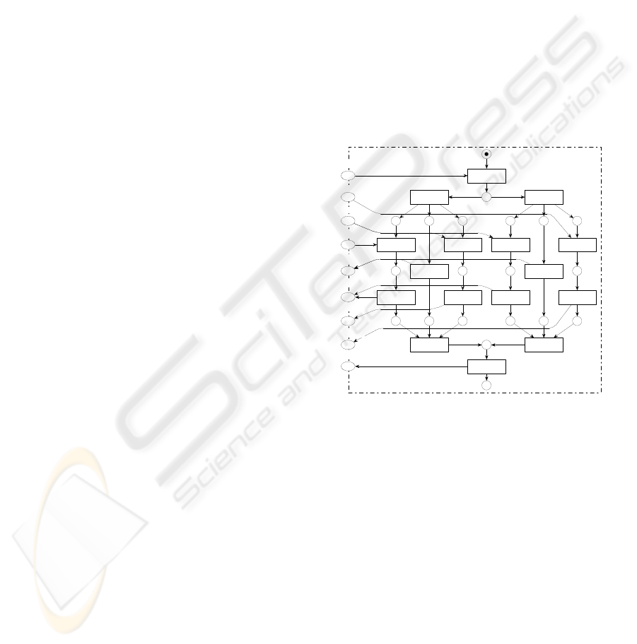
2004). Figure 4 shows the communication graph of
module Online Tickets. Some parts of the graph a
drawn with dashed lines – we will com to this later.
[s]
[o]
[p]
[n]
[c]
[b,t]
[o]
[o]
[o]
[a,t]
[a]
[d]
[d]
[a]
[o]
[a,t]
[o]
[b,t]
[p]
[c]
[b,t]
[d,t]
[o]
[p]
[c]
[b]
[a]
[a]
[ ]
[d]
[ ]
[a,b,t]
[a]
[b]
[a,d,t]
[b,t]
[c]
[a,t]
[a,t]
[d,t]
v4
v2 v3
v1
v0
h2 h3
h1
h0
h12 h13 h14 h15
h10 h11
h9h8h6 h7
h5 h4
v9
v7 v8v6v5
v14
v12
v13
v11v10
Figure 4: Communication graph
The root node v0 is labeled with the initial state of
the module ([0] stands for one token on place p0). An
edge starting at a visible node is labeled with a bag of
messages send by the environment – called input, an
edge starting at a hidden node is labeled with a bag of
messages send by the module – called output. Thus,
a path within this graph represents a communication
sequence between the module an an environment.
Some visible nodes are labeled with more than one
state (e. g. v1). In that case, after the communica-
tion along the path towards this node, the module has
reached or will reach one of these states.
The communication graph of a given module is
well defined and we present an algorithm for its calcu-
lation. But before we can do so, we have to introduce
some functions on workflow modules:
Activated input Concerning a given state of a mod-
ule, an activated input is a minimal bag of messages
the module requires from an environment either to
produce an output or to reach the final state. The
function I NP yields the set of activated inputs.
Successor state Concerning a given state of a mod-
ule, a successor state is a reachable state that is
maximal concerning one run of the module. The
function N XT yields the set of successor states.
Possible output Concerning a given state of a mod-
ule, a possible output is a maximal bag of messages
the is send by the module while reaching a succes-
sor state. The function O UT yields the set of possi-
ble outputs.
Communication step The tuple (z, i, o, z
0
) is called
communication step, if z, z
0
are states of a module,
i is an input and o is an output and (z
0
+ o) is a
successor state of (z + i). S(M) denotes the set of
all communication steps for a given module M .
ANALYSIS AND RE-ENGINEERING OF WEB SERVICES
423

All notions mentioned above are well defined based
on partial ordered run of the workflow module (see
(Martens, 2004)). Because of the limited space, we do
not go into further details. Applying these notions, we
are now able to present the construction of the com-
munication graph. The algorithm starts with the root
node v
0
labeled with the initial state:
1. For each state within the label of v
i
calculate the
set of activated inputs:
S
z∈m(v
i
)
INP(z).
2. For each activated input i within this set:
(a) Add a new hidden node h, add a new edge
(v
i
, h) with the label i.
(b) For each state within the label of v
i
calculate the
set of possible outputs:
S
z∈m(v
i
)
OUT(z + i).
(c) For each possible output o within this set:
i. Add a new visible node v
i+1
, add a new edge
(h, v
i+1
) with the label o.
ii. For each state z ∈ m(v
i
) and for each commu-
nication step (z, i, o, z
0
) ∈ S(M ) add z
0
to the
label of v
i+1
.
iii. If there exists a visible node v
j
such that
m(v
i+1
) = m(v
j
) then merge v
j
and v
i+1
.
Otherwise, goto step 1 with node v
i+1
.
The communication graph of a module contains that
information, a “good natured” environment can de-
rive. That means, the environment always sends as
little messages as possible, but as much as necessary
to achieve an answer resp. to terminate the process in
a proper state. By considering all reachable successor
states together with all possible outputs, the choices
within the module are not restricted.
3.3 The usability graph
By help of the communication graph we can decide
the usability of a module. A communication graph
may have several leaf nodes: none, finitely or in-
finitely many. Figure 4 shows a graph with three leaf
nodes: v4, v13 and v14. In each communication graph
there is at most one leaf node labeled with the defined
final state of the workflow module (v4). All other leaf
nodes contain at least one state, where there are mes-
sages left or which marks a deadlock within the mod-
ule (v13 and v14).
That means: If we build an environment that com-
municates with the module according to the labels
along the path to such a leaf node, this environment
does not utilize the module. Therefore, we call the
communication sequence defined by such a path an
erroneous sequence. Now we can try to eliminate all
erroneous sequences. We call a subgraph of the com-
munication graph that does not contain any erroneous
sequences an usability graph of that module.
Definition 3.2 (Usability graph).
A subgraph U of the communication graph C is called
usability graph, iff
• U contains the root node and the defined leaf node
(labeled with the defined final state of the workflow
module) of C.
• For each hidden node within U all outgoing edges
are within U, too.
• Each node within U lies on a path between the root
node and the defined leaf node.
?
A usability graph of a module describes, how to use
that module. For the precise, mathematical definition
see (Martens, 2004). A communication graph may
contain several usability graphs.
Figure 4 shows the only usability graph of mod-
ule Online Tickets drawn by solid lines. Now we can
construct a more clever customer than we did at the
beginning of this section: A customer send its name
[n] and awaits the special offers [s]. Afterwards, he
sends the order [o].
If he receives the business terms [b], he was classi-
fied as standard customer. Thus, he pays [p] and gets
an acknowledgement and the ticket [a, t]. Otherwise,
he is a premium customer and receives an acknowl-
edgement [a]. In that case, he transmits his conditions
[c] and receives finally the current discount level and
the ticket [d, t].
If we look at Figure 4, there is a path from the node
v1 to the defined leaf node v4 via h5, i. e. the mod-
ule might serve properly the customer from beginning
of this section. But, the decision wether or not the
path to h5 is continued towards the node v4 is up to
the module. An environment has no further influence.
Hence, a utilizing environment must prevent to reach
this node.
3.4 Theorem of usability
An usability graph U can easily be transformed into
an environment of the workflow module – we call it
the constructed environment, denoted by Γ(U). The
next section presents the generation of an abstract rep-
resentation for a given workflow module (Figure 5).
The construction of the environment takes place ana-
logically, just by switching the directions of commu-
nication. We need the constructed environment to de-
cide the usability of some cyclic workflow modules.
Now we can formulate the correlation between the
usability of a workflow module and the existence of a
usability graph:
Theorem 3.1 (Usability).
Let M be a workflow module and let C be the com-
munication graph of M.
• The module M is not usable, if C contains no finite
usability graph.
ICEIS 2004 - INFORMATION SYSTEMS ANALYSIS AND SPECIFICATION
424
• An acyclic module M is usable, if and only if C
contains at least one finite usability graph.
• An cyclic module M is usable, if C contains at least
one finite usability graph U and the composed sys-
tem M ⊕ Γ(U) is weak sound.
?
The proof applies the precise definition and underly-
ing structures of Petri net theory. Hence, we omit
the proof here. All proofs together with informa-
tion about the complexity of our algorithms can be
found in (Martens, 2004). The algorithms are also
implemented within an available prototype (Martens,
2003b).
4 RE-ENGINEERING
As we have shown, the workflow module of the online
ticket service is usable. Nevertheless, the representa-
tion is not adequate for publishing the service within a
public repository. We already have address the prob-
lems of a customer who wants to use this service.
4.1 Views on Web services
Anyhow, it is not correct to call the module shown
in Figure 3 a “bad” model in general. The quality of
a model always depends on its purpose. Concerning
Web services we can distinguish two purposes, that
come along with totally different requirements.
On the one hand, a Web service is modeled to de-
scribe the way it is executed. Such a model is useful
for the provider of the service. Hence, it is called the
private view model and needs to contain a lot of de-
tails on the internal structure. The module shown in
Figure 3 is a good candidate for a private view model,
because it reflects the organization structure (three in-
dependent departments).
On the other hand, a Web service is modeled to de-
scribe how to use it. Such a model has to be easily
understandable, because a potential requestor of the
service wants to decide, whether or not that service
is compatible to his own component. Hence, such a
model is called the public view model. For that pur-
pose the module Online Tickets is no adequate model
of the services.
As a consequence thereof, we need another model
of this services. Because of many reasons, it is not ef-
ficient to build a new public view model from scratch.
Instead the public view model should be automati-
cally derived from the private view model.
4.2 Transformation
Basically, the transformation of private view model
into a public view model is an abstraction from de-
tails. Hence, a common approach focusses on elimi-
nation and fusion of elements within a given model.
In this paper, we present a different approach. A po-
tential requestor of a Web service ist not urgently in-
terested in the (possibly simplified) structure of a pro-
cess. For him, the behavior is of vital importance.
As we have discussed, the usability graph is an ade-
quate representation of the usable behavior for a given
Web service. Thus, the public view model should be
derived from the usability graph of the private view
model.
[s]
[o]
[p]
[p]
[n]
[b] [a]
[d,t]
[a,t]
n
k
w
g
r
a
b
z
t
v4
v2
v3
v1
v0
h2 h3
h1
h0
Usability
graph
?o
?n
?p
!a,t
!s
!a
?c
!d,t
!b
v1
v2 v3
v0
v4
h2
h1
h3
h0
Module
Online Tickets
Public View
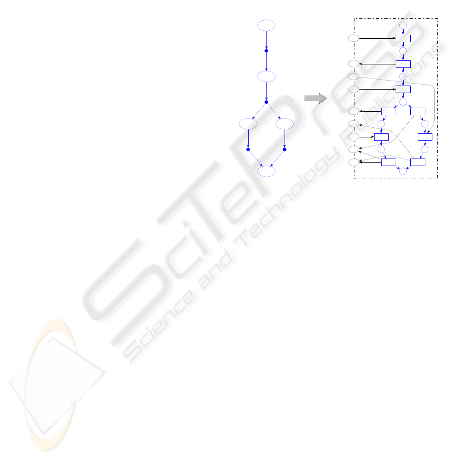
Figure 5: A module and its environment
Figure 5 shows on the left side the usability graph
of the module Online Tickets. We have omit the label-
ing of the visible states, because this is of no interest
for the transformation. On the right side, Figure 5
shows public view model of the online ticket service.
The transformation is very simple: Each node of the
usability graph is mapped to a place within the mod-
ule and each edge of the graph is mapped to a transi-
tion that is put in between the two places representing
the source and target nod of the edge. Finally, the
interface places are added and each transition is con-
nected to these places according to the label of the
edge.
As the result, a customer can easily understand,
how to use the service. The independency between
the canvassing department and the accounts depart-
ment was replaced be a causal order, because now
utilizing environment of this module could commu-
nicate with both departments concurrently.
A public view model of a Web service, that is gen-
erated by our algorithm contains only the usable be-
havior of the original model. Thus, the both views
on the process are not equivalent. We require just a
simulation relation: Each utilizing environment of the
public view model has to be a utilizing environment
of the private view model. In the very most cases this
property holds per construction. There are a few ab-
ANALYSIS AND RE-ENGINEERING OF WEB SERVICES
425

normal cases, where we have to prove the simulation
relation and to adjust the result in case. More details
can be found in (Martens, 2004).
5 SUMMARY
In this paper, we have sketched a framework for mod-
eling business processes and Web services by help of
Petri nets. This framework has enabled us to specify
a fundamental property of such components – usabil-
ity. We have also presented algorithms to verify this
property locally. Moreover, the our approach yields a
concrete example how to use a given Web services.
Beside the results presented here, the notion of us-
ability and the formalism of communication graphs
are the basis for further investigations on Web ser-
vices. On the one hand, the analysis of usability offers
a starting point for the simplification of Web service
models and for re-engineering of such components.
On the other hand, the equivalence of two Web ser-
vices can be decided. This is exceedingly important
for a dynamic exchange of components within a run-
ning system: Does the new component behave exactly
the way the replaced component did?
All presented algorithms are implemented within a
prototype. Currently, we try to improve the efficiency
of the algorithms by the application of partial order
reduction techniques. Due to this approach we will be
able to handle much larger workflow modules which
emerge by transformation of a real world modeling
language into our framework, i. e. BPEL4WS (BEA
et al., 2002).
REFERENCES
BEA, IBM, Microsoft, and SAP (2002). BPEL4WS– Busi-
ness Process Execution Language for Web Services.
Version 1.1.
Gottschalk, K. (2000). Web Services architecture overview.
IBM developerWorks, Whitepaper. http://ibm.
com/developerWorks.
Martens, A. (2003a). On compatibility of web services.
Petri Net Newsletter, (65):12–20.
Martens, A. (2003b). WOMBAT4WS– Workflow Mod-
eling and Business Analysis Toolkit for Web Ser-
vices. Humboldt-Universität zu Berlin, Man-
ual. http://www.informatik.hu-berlin.
de/top/wombat.
Martens, A. (to appear 2004). Verteilte Geschäftsprozesse –
Modellierung und Verifikation mit Hilfe von Web Ser-
vices. PhD thesis, Humboldt-Universität zu Berlin.
Martens, A., Stahl, C., Weinberg, D., Fahland, D., and Hei-
dinger, T. (2004). BPEL4WS– Semantik, Analyse
und Visualisierung. Informatik-Bericht, Humboldt-
Universität zu Berlin.
Reisig, W. (1985). Petri Nets. Springer-Verlag, Berlin, Hei-
delberg, New York, Tokyo, eatcs monographs on the-
oretical computer science edition.
van der Aalst, W. M. P. (1998a). The application of petri
nets to workflow management. Journal of Circuits,
Systems and Computers, 8(1):21–66.
van der Aalst, W. M. P. (1998b). Modeling and analyz-
ing interorganizational workflows. In Lavagno, L.
and Reisig, W., editors, Proceedings of CSD’98, pages
262–272. IEEE Computer Society Press, Fukushima,
Japan.
ICEIS 2004 - INFORMATION SYSTEMS ANALYSIS AND SPECIFICATION
426
