
INCORPORATING THE ELEMENTS OF THE MASE
METHODOLOGY INTO AGENT OPEN
Q.-N. N. Tran, B. Henderson-Sellers, J. Debenham
University of Technology, Sydney, Australia
Keywords: Agent-oriented methodology, MASE, OPEN
Abstract: Enterprise-wide, web-based systems can be assisted in their construction by the use of agents and an agent-
oriented methodology.
As part of an extensive research programme to create such an AO methodology by
combining the benefits of method engineering and existing object-oriented frameworks (notably the OPF),
we have analysed here contributions to the OPF repository of process components from the MASE agent-
oriented methodology, identifying three new Tasks, one additional Technique and two new Work Products.
1 INTRODUCTION
Construction of an enterprise-wide, web-based
system can be assisted by using agents and an agent-
oriented methodology. While there are an increasing
number of stand-alone methodologies (e.g. Gaia:
Wooldridge et al., 2000), none supports all process
elements across the full lifecycle.
Many agent-oriented methodologies extend the
ideas already established in the field of object-
oriented methodologies, adding agent-specific issues
such as social interaction, autonomy and reasoning
processes and modifying and extending other
existing OO support to apply also to agents. For
example, Gaia (Wooldridge et al., 2000) takes as its
basis the Fusion methodology of Coleman et al.
(1994); ADELFE (Bernon et al., 2002) starts with
RUP (Kruchten, 1999)
1
and Agent OPEN
(Debenham and Henderson-Sellers, 2003a,b)
extends the OPEN Process Framework or OPF (e.g.
Firesmith and Henderson-Sellers, 2002).
It is also increasingly being recognized (e.g.
Cockburn, 2000) that the idea of a single process to
suit all kinds of software project is an unattainable
“holy grail” since software projects vary greatly
depending on many factors, such as organizational
constraints, business constraints, technology issues
and application factors (Firesmith and Henderson-
Sellers, 2002). Creating a suite of processes can best
be undertaken using the concepts of method
1
Although the citation is actually to the Unified Software
Development Process of Jacobson et al. (1999)
engineering (Brinkkemper, 1996; Ter Hofstede and
Verhoef, 1997; Ralyté and Rolland, 2001).
Combining these two threads, we propose here a
further extension of the OPF, based on method
engineering, to construct a wide range of process
instances. Preliminary work has been undertaken to
create initial support for agents (Debenham and
Henderson-Sellers, 2003a). Here we report on the
continuing research project that aims to ensure that
all current mainstream AO methodologies can be
supported via method engineering and the OPF by
careful analysis of each AO methodology in turn.
Here, we focus specifically on ensuring that
concepts from the MASE AO methodology of
DeLoach (1999); Wood and DeLoach (2000); Wood
(2000) are either already supported in or provide
candidates for new process components in the OPF
repository.
Section 2 outlines the ideas behind method
engineering (ME) whereas Section 3 describes the
basic characteristics of the OPEN Process
Framework or OPF (Firesmith and Henderson-
Sellers, 2002). In Section 4, we describe the basics
of the MASE methodology and then in Section 5
describe the elements of the agent-oriented
methodology MASE (DeLoach, 1999; Wood, 2000;
Wood and DeLoach, 2000) that not currently
supported in the OPF and which we therefore
propose for addition to the OPF repository.
380
N. Tran Q., Henderson-Sellers B. and Debenham J. (2004).
INCORPORATING THE ELEMENTS OF THE MASE METHODOLOGY INTO AGENT OPEN.
In Proceedings of the Sixth International Conference on Enterprise Information Systems, pages 380-388
DOI: 10.5220/0002597103800388
Copyright
c
SciTePress
2 METHOD ENGINEERING
A method (or methodology) is a combination of a
process and a set of products. The product side is
generally described using a modelling language such
as the UML (OMG, 2001) and a suite of appropriate
diagrams. Consequently, a major interest in method
engineering is in fact the process-focussed elements.
Thus, we will use terms such as method engineering
and process engineering essentially as synonyms and
similarly refer to the method fragments in the
repository as either method chunks (Rolland and
Prakash, 1996) or process components (e.g.
Firesmith and Henderson-Sellers, 2002). The
discipline of method engineering (ME) itself (e.g.
Brinkkemper, 1996) provides a rational approach to
the construction of methods from method fragments,
which are typically stored in a repository. The
method itself is then constructed by selection of
appropriate method fragments (Brinkkemper et al.,
1998; Rolland et al., 1999) followed by their
configuration in such a way as to satisfy the
requirements for the method (Ralyté and Rolland,
2001) and create a meaningful overall method
(Brinkkemper et al., 1998). A method targetted at a
particular project or environment is known as a
situated or situational method and the means of its
derivation known as situational method engineering
(SME) (Ter Hofstede and Verhoef, 1997).
Method engineering implicitly relies on the
existence of a process/method metamodel. By using
the OPF we make this metamodel explicit since a
major characteristic of the OPF is its underpinning
metamodel. It is then easy to both generate method
fragments from the metamodel in a consistent way
and also to ensure that repository-stored process
components have been rigorously defined. In other
words, a metamodel imposes some rules upon how a
method should be constructed. Such rules also
automatically impose some granularity constraints as
noted in Brinkkemper et al. (1998). A second set of
rules is needed to assist in process construction.
3 A BRIEF OVERVIEW OF THE
OPEN PROCESS FRAMEWORK
The OPEN (Object-oriented Process, Environment,
and Notation) Process Framework (OPF) (Firesmith
and Henderson-Sellers, 2002) exemplifies the use of
ME within, at least initially, an object-oriented
software development context. Its metamodel
defines five major high level metaclasses: Work
Product (inputs and outputs to Work Units), Work
Units (describing what jobs need to be undertaken
and how), Producers (the actors, usually human,
expending the effort), Languages (to communicate
ideas and results) and Stages (to impose an overall
temporal sequencing).
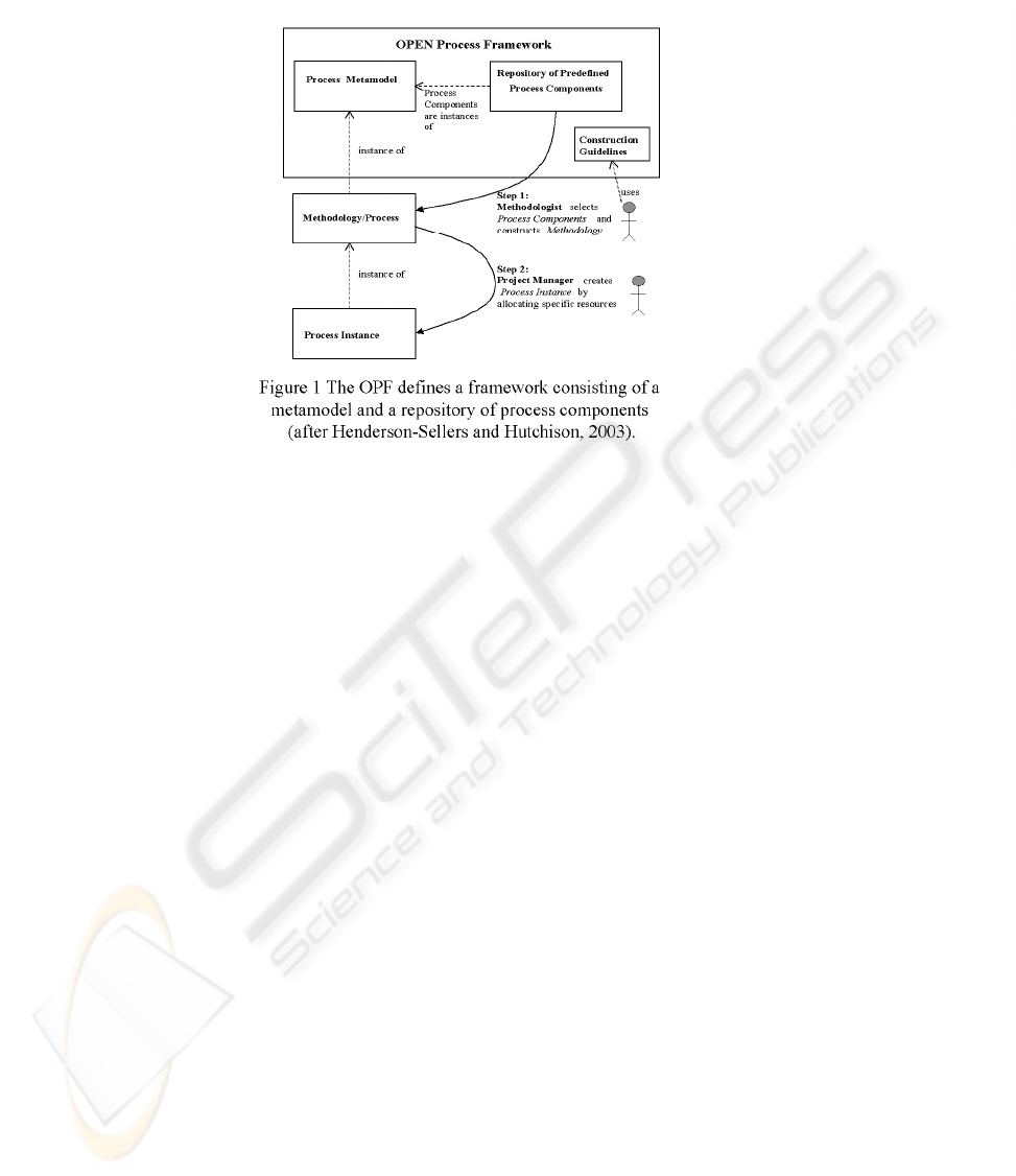
From each metamodel class/subclass, instances
can be generated and stored in the OPF repository
(Figure 1). The OPF calls these process components,
from which a selection is made specifically based on
the current project or organizational demands. This
results in a situational method. Rules for this
situational method engineering are also contained
within the OPF repository. This gives a high degree
of flexibility to the process engineer in undertaking
INCORPORATING THE ELEMENTS OF THE MASE METHODOLOGY INTO AGENT OPEN
381

process construction and tailoring to local
conditions. A company-customized OPEN version is
then “owned” by the organization, becoming their
own internal standard, while retaining compatibility
with the global OPEN user community.
Initially, the OPF repository contained about 30
predefined instances of Activity, 160 instances of
Task and 200 instances of Techniques (the three
main kinds of Work Unit) as well as multiple
instances of Role, Stage, Language etc. Some of
these are orthogonal to all others in their group and
some overlap. For example, there are several
Techniques in the repository for finding objects e.g.
textual analysis, use cases simulations, CRC card
techniques. Consequently, during process
construction both association and integration
strategies (Ralyté and Rolland, 2001) are needed.
4 MAJOR ELEMENTS OF MASE
MASE (DeLoach, 1999; Wood, 2000; Wood and
DeLoach, 2000) aims to guide the designer through
the multiagent-system development process from an
initial system specification to a set of formal design
documents. It includes two phases: analysis and
design. The former deals with the specification of
system goals, use cases, sequence diagrams, roles,
and tasks, while the latter uses the analysis phase’s
outputs to design agent classes, agent interactions,
and agents’ internal components.
MASE is drawn from the legacy of object-
oriented methodologies such as Rumbaugh’s Object
Modeling Technique (OMT) and the Unified
Modeling Language (UML). It also builds upon the
pre-existing work in the realm of agents and
multiagent systems e.g. Kendall and Zhao (1998)
and Kinny et al. (1996). MASE is independent of
any particular agent architecture, programming
language, or communication framework. It is also
capable of tracking changes throughout the
development process. Every model created during
the analysis and design phases can be traced forward
or backward through the different steps to other
related models. However, various limitations of the
methodology are the assumptions that the agent
system is closed, static, and involving only one-to-
one inter-agent conversations.
MASE is supported by agentTool – a
graphically-based, fully interactive software
engineering tool that supports all MASE’s steps as
well as code generation and automatic verification of
inter-agent communications.
4.1 Stages used in MASE
Cycle: MASE is iterative across all phases with the
intent that successive “passes” will add detail to the
models until a complete and consistent system
design is produced. This description fits OPF’s
“Iterative, Incremental, Parallel Life Cycle” model.
Phases: MASE covers Analysis and Design. In
terms of OPEN’s phases, MASE supports
“Initiation” and “Construction”.
4.2 Tasks characterizing MASE
• ‘Capturing Goals’: includes 3 sub-tasks
o ‘Identifying Goals’
o ‘Creating Use Cases’
o ‘Structuring Goals’
• ‘Specifying Roles’ involves identifying and
modelling a set of roles required for the
achievement of the captured goals. In MASE
(and in many other MAS methodologies), role is
considered as a “first-class” concept of analysis
and design, a major focus of modelling. In many
OO approaches, including UML V1.x, role is
downplayed. However, role is pre-eminent in an
OO methodology like OORam (Reenskaug et
al., 1996) and this more significant importance
for role is echoed in the OPF.
• ‘Identifying Tasks’ involves associating each
role with a set of tasks to detail how the role can
fulfil a goal.
• ‘Applying Use Cases’: involves transforming
use cases into sequence diagrams.
• ‘Creating Agent Classes’: involves identifying
agent classes from roles and constructing an
Agent Class Diagram that shows agent classes
and conversations between them.
• ‘Constructing Conversations’: A MaSE
conversation defines a coordination protocol
between two agents. Conversations can be built
by adding all the possible states and transitions
derived from the sequence diagrams and tasks.
• ‘Assembling Agents’: involves identifying and
constructing the internal components of each
agent class. A designer can either define
components from scratch or use pre-existing
components.
• ‘System Deployment’: involves instantiating
agent classes with agents, and allocating the
agents to nodes.
ICEIS 2004 - SOFTWARE AGENTS AND INTERNET COMPUTING
382
4.3 MASE Techniques
• For ‘Identifying Goals’: MASE suggests
analyzing detailed technical documents, user
stories, formalized government specifications,
and scenarios.
• For ‘Creating Use Cases’: MASE recommends
standard ‘Scenario Development’ techniques.
• For ‘Structuring Goals’: MASE suggests
hierarchically organizing goals in the order of
importance. Each level contains goals that are
roughly equal in scope, level of detail and
importance. All sub-goals must relate
functionally to their parent.
• For ‘Specifying Roles’: MASE derives roles
from goals via a generally one-to-one
correspondence. Similar or related goals, and
goals that share a high degree of cohesion, may
combined into single roles. Some goals that
involve distribution may imply distributed roles.
• For ‘Identifying Tasks of each role’: MASE
does not discuss techniques for task
identification. However it denotes that different
roles should not share the same task. Shared
tasks are a sign of improper role decomposition,
and should be placed in separate dedicated
roles.
• For ‘Applying Use Cases’: MASE follows
standard OO techniques for transforming use
cases into sequence diagrams. A few adapt-
ations made to the conventional techniques are
that every participant in a MASE’s sequence
diagram should be a role, and information flows
between participants should represent instances
of events occurring between the two roles.
• For ‘Creating Agent Classes’: MASE derives
agent classes from roles via a generally one-to-
one correspondence. In some cases, multiple
roles may be combined into a single class, or a
single role mapped to multiple agent classes.
• For ‘Constructing Conversations’: MASE
suggests deriving inter-agent conversations
from inter-role Sequence Diagrams and Task
State Diagrams.
• For ‘Assembling Agents’: MASE recommends
three methods for assembling components to
define an agent class: 1) to select a pre-defined
agent architecture and either instantiate the
components as is or modify their attributes and
methods; 2) to use pre-defined components and
assemble them into a user-defined agent
architecture; or 3) to define both components
and agent architecture from scratch.
• For ‘System Deployment’: The instantiation and
allocation of agents in MASE are guided by the
considerations of communication traffic and
processing powers.
4.4 MASE Work Products
• Goal Hierarchy Diagram: this is a simple tree
structure where goals are represented as boxes
and goal-subgoal relationships as directed
arrows from parents to children.
• Use Case Diagrams: (identical to UML)
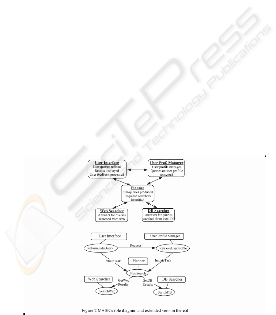
• Role Diagram: MASE adopts the Role Diagram
INCORPORATING THE ELEMENTS OF THE MASE METHODOLOGY INTO AGENT OPEN
383
from Kendall’s (2000) Role Model (Figure 2).
Lines between roles show possible communi-
cation paths between roles. Goals associated
with each role are listed under the role name.
An extended version of the Role Diagram
shows the set of tasks associated with each role
(denoted as ellipses attached to the role).
• Task State Diagram: (corresponds to UML State
Transition/Statechart Diagram)
• Sequence Diagram: (corresponds to UML
Sequence Diagrams, with actors being roles.)
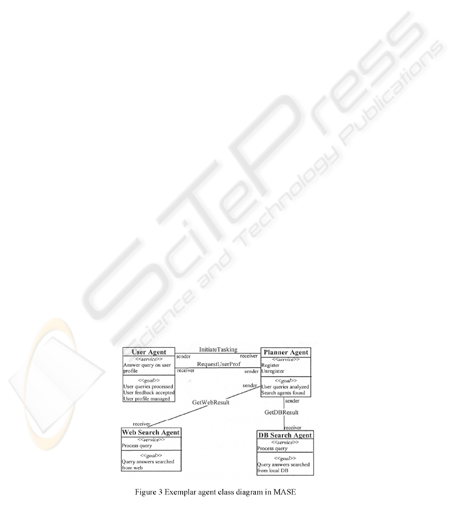
• Agent Class Diagram: different from UML
Class Diagram in terms of
o Class interface: Each OO class has
attributes and operations. Each MASE
agent class has a goal and may or may
not provide services to other agents.
o Semantics of relationships between
classes: in a UML Class Diagram, the
connections represent association,
composition, aggregation or inheritance
relationships between classes. In MASE,
the connections between classes denote
conversations that are held between agent
classes, and the label next to each agent
class represents the role the agent plays
in a conversation. An example of a
MASE-recommended Agent Class
Diagram is shown in Figure 3.
• Communication Class Diagram: corresponds to
UML State Transition Diagram. However, a
Communication Class Diagram focuses on the
states of an agent during a particular
conversation. Two state diagrams are required
for each conversation (one for the initiator and
one for the responder). The labelling on the arcs
follows conventional UML notation rec-
mess(arg1)[cond]
∧
trans-mess(arg2). The
actions specified within a state represent
processing required by the agent.
• Agent Class Architecture Diagram: MASE does
not impose any template for this diagram,
although a UML Component Diagram seems to
be a good substitute, based on MASE’s use of
CBSE. MASE also suggests using a State
Diagram to model the sequence of events
passed from one component to another.
• Deployment Diagram: different from UML
Deployment Diagram as follows:
o The three-dimensional boxes represent
nodes in UML, but agents in MASE
o The connecting lines represent physical
connections between nodes in UML, but
conversations between agents in MASE
o MASE uses dashed-line box around agents
to indicate that these agents are housed
on the same physical platform.
[Note: DeLoach (1999) suggests a Communication
Hierarchy Diagram, which is not mentioned in other
references. This diagram simply defines the
relationships between the various conversations
within MAS. The conversations themselves are
described in Communication Class Diagrams.]
4.5 Languages discussed in MASE
MASE proposes its own modelling languages but
claims to be independent of any particular
implementation language, recommending:
• AgML (Agent Modelling Language): a
graphically based language which describes the
types of agents in the system and their interfaces
to other agents. Although AgML diagrams look
similar to OMT or UML diagrams, they have
additional features and have modified
traditional OO semantics to capture notions of
agency and cooperative behaviour.
• AgDL (Agent Definition Language): based on
ICEIS 2004 - SOFTWARE AGENTS AND INTERNET COMPUTING
384

first-order predicate logic to describe the
internal behaviour of each agent (not supported
in the current OPF repository).
5 ADDING SUPPORT TO THE
OPF DERIVED FROM MASE
In this section, we outline the various Tasks,
Techniques and Work Products that are proposed in
this paper as additions and modifications to the OPF
repository in order to incorporate agency concerns as
identified in MASE. These new process components
Table 1: Mapping between MASE and OPF
MASE Supporting OPF Tasks Supporting OPF Techniques
Capturing goals Model goals OPF user requirements techniques
Tropos techniques
Hierarchical task analysis
Specifying roles Identify agents’ roles Role Modelling
Construct the Object Model
Identify CIRTs
Identifying tasks Model agents’ roles Hierarchical task analysis
Determine agent reasoning Responsibility modelling
Applying use cases Construct the Object Model
Creating agent classes Model agents’ roles Intelligent agent identification
Map roles onto classes Agent internal design (new)
Construct the agent model (new)
Constructing conversations Construct agent conversations (new) Interaction modelling
State modelling
Assembling agents Design agent internal structure (new) Agent internal design (new)
System deployment Create a software/system architecture Coding
Distributed systems partitioning and allocation
have been identified directly from the MASE
literature and are summarized in Table 1.
5.1 Existing support and mapping
between OPF and MASE
The capture of goals is supported in Agent OPEN
through the Task: ‘Model goals’ (Henderson-Sellers
et al., 2003b). Roles are covered by Task: ‘Identify
agents’ roles’ (Debenham and Henderson-Sellers,
2003b) and standard tasks of ‘Construct the Object
Model’ and ‘Identify CIRTs’ which, together, cover
the identification and modelling of roles.
MASE’s Task ‘Identifying tasks’ is mirrored by
Agent OPEN’s “Model agents’ roles” and
“Determine agent reasoning” (Debenham and
Henderson-Sellers, 2003b) because tasks in MASE
represent the functionality of agent roles. ‘Construct
the Object Model’ Task of OPF covers the MASE
Task of ‘Applying Use Cases’ although it should be
noted that actors in the sequence diagrams should be
roles rather than classes and objects.
OPF’s Tasks ‘Construct the Object Model’ and
‘Identify CIRTs’ only cover the identification of OO
classes. Therefore a new Task: ‘Model agents’ roles’
was introduced by Debenham and Henderson-Sellers
(2003a). Using this and the existing OPF Task: ‘Map
roles on to classes’ offers adequate support. While
the linkages between objects in the Object Model
represent association, aggregation, and inheritance
relationships, the relationships between agents in the
Agent Class Diagram represent inter-agent
conversations. Thus, we need to consider whether
the conventional relationships in the context of OO
systems are relevant to AO systems. We thus
propose three new Tasks: ‘Construct the agent
model’, ‘Design agent internal structure’ and
‘Construct agent conversations’ plus a new
Technique: ‘Agent internal design’.
With respect to techniques recommended by
MASE, goal identification is supported in the OPF
by several standard user requirements techniques as
well as the Agent OPEN techniques “borrowed”
from Tropos (Henderson-Sellers et al., 2003b),
together with techniques for structuring goals. In
addition, the pre-existing OPF Technique:
‘Hierarchical Task Analysis’ is also available.
INCORPORATING THE ELEMENTS OF THE MASE METHODOLOGY INTO AGENT OPEN
385

For MASE’s ‘Specification of roles’ techniques,
OPF offers the Technique: ‘Role Modelling’, which
covers various aspects of role modelling, although is
weak on guidance for the identification of roles.
MASE’s ‘Identifying tasks of each role’ technique
corresponds to ‘Hierarchical Task Analysis’ and
‘Responsibility modelling’ techniques in the OPF,
even though these techniques need to be extended to
cater for roles/agent classes. MASE also suggests
producing a State Diagram for each task, not
mentioned in these two OPF techniques.
For techniques to support MASE’s ‘Creating
Agent Classes’, the OPF offers Technique:
‘Intelligent agent identification’. This technique,
however, currently covers only the need for agents
and agent modelling notation. Much extension is
required. OPF also offers various techniques for OO
class identification/modelling (such as ‘Abstract
Class Identification’ and ‘Class Naming’), which
can be extended to support the identification of
agent classes, taking into account the major
differences between OO and agent classes – e.g.,
agent classes are generally more coarse-grained than
OO classes. (The OPF ‘Granularity’ Technique, in
particular, should be extended to account for this
difference). Consequently we propose here a new
Technique: ‘Agent internal design’.
Conversations can readily be constructed using
OPF Techniques: ‘Interaction modelling’ and ‘State
modelling’, perhaps with minor extensions.
Techniques to support the assembly of agents in
MASE are found in OPF’s new Technique: ‘Agent
internal design’. Finally, system deployment issues
are supported by Technique: ‘Coding’ and
distribution allocation issues through Technique:
‘Distributed systems partitioning and allocation’.
Overall, three new Tasks are identified together
with one new Technique. Additionally, two new
Work Products are recommended for inclusion into
the OPF repository (see below).
5.2 New Tasks
An OPF Task describes something that needs to be
done. Its name is verblike, describing an action to be
undertaken. The three new Tasks are described
formally as follows.
TASK NAME: Construct the agent model
Focus: Static architecture
Typical supportive techniques: Intelligent agent
identification, Control architecture
Explanation: An analogue of the “object model” as
the main description of the static architecture needs
to be constructed. This model will show the agents,
their interfaces and how they are connected both
with other agents and other objects within the
system being designed.
TASK NAME: Design agent internal structure
Focus: Internal structure of agents
Typical supportive techniques: Agent internal
design, 3-layer BDI model, Reactive reasoning
Explanation: Using an appropriate model for the
internal agent architecture, such as the BDI model,
the internal structure of each agent needs to be
determined. If a hybrid architecture is used, both
ECA rules (event-condition-action rules) and I-rules
(inference rules) may be needed. If using a BDI
architecture, then goals and plans will be needed
(see Agent OPEN Tasks: Model Goals and Models
Plans: Henderson-Sellers et al., 2003b). When using
Prometheus, high level capabilities are identified and
iteratively decomposed, finally resulting in plans,
internal events and data.
TASK NAME: Construct agent conversations
Focus: Detailed agent-agent interactions
Typical supportive techniques: Scenario
development, Collaborations analysis, Interaction
modelling, State modelling
Explanation: Interactions and their protocols are
modelled in agent-oriented systems by conversations
that formally define the coordination protocol
between any pair of agents. The construction of
agent conversations can be accomplished by
identifying all possible states and transitions which
are themselves in turn derived from an analysis of
the sequence diagrams and tasks.
5.3 New Techniques
An OPF Technique describes how a Task is
accomplished i.e. “how” something is done. One
new Technique is identified and described here.
TECHNIQUE NAME: Agent internal design
Focus: Internal features of an agent
Typical tasks for which this is needed: Design agent
internal structure
Technique description: The fine detail of an
individual agent must be described in terms of its
attributes and operations (as for objects) but more
importantly in terms of its goals, plans, capabilities,
responsibilities, events responded to and pre- and
post-conditions.
Technique usage: Document each of these internal
characteristics (or features) of every agent in the
system. The detail should be sufficient for coding to
take place easily from these design specifications.
Deliverables: Capability diagram
ICEIS 2004 - SOFTWARE AGENTS AND INTERNET COMPUTING
386

5.4 New Work Products
An OPF Work Product describes the input or output
of a Task.
NAME: Goal hierarchy diagram
OPF CLASSIFICATION: Architectural set
RELATIONSHIP TO EXISTING WORK PRODUCT:
None
BRIEF DESCRIPTION: A graphical description of
the hierarchical or tree structure of goals. Goals and
subgoals are represented by boxes and directed
arrows run from each goal to each of its subgoals.
NAME: Role diagram
OPF CLASSIFICATION: Architectural set
RELATIONSHIP TO EXISTING WORK PRODUCT:
Class diagram but emphasizing roles rather than
classes
BRIEF DESCRIPTION: Although a role diagram, as
described in MASE, can be documented using UML,
particularly Version 2, the increased importance of
roles in agent technology as compared to object
technology suggests that this should be a separate,
named diagram type. It can be documented using
standard UML role notation.
6 SUMMARY AND
CONCLUSIONS
As part of an extensive research programme to
combine the benefits of method engineering and the
OPF to create a highly supportive methodological
environment for the construction of agent-oriented
information systems, we have analysed here
contributions from the MASE AO methodology. We
have identified three new Tasks, one new Technique
and two new Work Products, but no additional Roles
or Stages.
ACKNOWLEDGEMENTS
We wish to acknowledge financial support from the
UTS Research Excellence Grants Scheme.
REFERENCES
Bernon, C., Gleizes, M.-P., Picard, G. And Glize, P., 2002,
The ADELFE methodology for an intranet system
design, presented at AOIS2002, Toronto, 27-28 May
Brinkkemper, S., 1996, Method engineering: engineering
of information systems development methods and
tools, Inf. Software Technol., 38(4), 275-280.
Brinkkemper, S., Saeki, M. and Harmsen, F., 1998,
Assembly techniques for method engineering.
Proceedings CAISE 1998, Springer Verlag, 381-400.
Cockburn, A., 2000, Selecting a project’s methodology,
IEEE Software, 17(4), 64-71
Coleman, D., Arnold, P., Bodoff, S., Dollin, C. and
Gilchrist, H., 1994, Object-Oriented Development.
The Fusion Method, Prentice Hall, USA, 313pp
Debenham, J. and Henderson-Sellers, B., 2003a,
Designing agent-based process systems - extending
the OPEN Process Framework, Chapter VIII in
Intelligent Agent Software Engineering (ed. V.
Plekhanova), Idea Group Publishing, 160-190.
Debenham, J. and Henderson-Sellers, B., 2003b, Towards
OPEN methodological support for agent-oriented
systems development, Procs. First International
Conference on Agent-Based Technologies and
Systems, University of Calgary, Canada, 14-24
DeLoach, S.A. 1999. Multiagent Systems Engineering: A
Methodology and Language for Designing Agent
Systems, Procs AOIS ’99.
Firesmith, D.G. and Henderson-Sellers, B., 2002, The
OPEN Process Framework. An Introduction, Addison-
Wesley, Harlow, Herts, UK
Henderson-Sellers, B. and Hutchison, J., 2003, Usage-
Centered Design (UCD) and the OPEN Process
Framework (OPF), Procs. forUSE2003, Second
International Conference on Usage-Centered
Design,
Ampersand Press, USA, 171-196
Jacobson, I., Booch, G. and Rumbaugh, J., 1999, The
Unified Software Development Process, Addison-
Wesley, Reading, MA, USA
Kendall, E.A., 2000, Agent Software Engineering with
Role Modelling. Procs. 1
st
International Workshop on
Agent-Oriented Software Engineering (AOSE-2000),
163-170.
Kendall, E.A. and Zhao, L., 1998, Capturing and
Structuring Goals, Workshop on Use Case Patterns,
Object Oriented Programming Systems Languages
and Architectures.
Kinny, D., Georgeff, M. and Rao, A., 1996. A
Methodology and Modelling Technique for Systems
of BDI Agents” Agents Breaking Away: Procs
Seventh European Workshop on Modelling
Autonomous Agents in a Multi-Agent World,
MAAMAW’96 (LNAIVolume 1038), 56-71.
Kruchten, Ph., 1999, The Rational Unified Process. An
Introduction, Addison-Wesley, Reading, MA, USA
OMG, 2001, OMG Unified Modeling Language
Specification, Version 1.4, September 2001, OMG
document formal/01-09-68 through 80 [Online].
Available http://www.omg.org
Ralyté, J. and Rolland, C., 2001, An assembly process
model for method engineering, in K.R. Dittrich, A.
INCORPORATING THE ELEMENTS OF THE MASE METHODOLOGY INTO AGENT OPEN
387

Geppert and M.C. Norrie (Eds.) Advanced Information
Systems Engineering), LNCS2068, Springer, Berlin,
267-283.
Reenskaug, T., Wold, P. and Lehne, O.A., 1995, Working
with Objects: The Ooram Software Engineering
Method, Manning, 366pp
Rolland, C. and Prakash, N., 1996, A proposal for context-
specific method engineering, IFIP WG8.1 Conf. on
Method Engineering, 191-208, Atlanta, GA, USA
Rolland, C., Prakash, N. and Benjamen, A., 1999, A multi-
model view of process modelling, Requirements Eng.
J., 4(4), 169-187
Ter Hofstede, A.H.M. and Verhoef, T.F., 1997, On the
feasibility of situational method engineering,
Information Systems, 22, 401-422
Wood, M., 2000, Multiagent Systems Engineering: A
Methodology for Analysis and Design of Multiagent
Systems. MS Thesis, USAF Inst. Technol..
Wood, M. and DeLoach, S.A. 2000, An Overview of the
Multiagent Systems Engineering Methodology. Procs.
1st International Workshop on Agent-Oriented
Software Engineering (AOSE-2000), 207-222
Wooldridge, M., Jennings, N.R. and Kinny, D., 2000, The
Gaia methodology for agent-oriented analysis and
design, J. Autonomous Agents and Multi-Agent
Systems, 3, 285-312
ICEIS 2004 - SOFTWARE AGENTS AND INTERNET COMPUTING
388
