
Hazard Analysis for Decentralized Charging Management of Electric
Vehicles
Stylianos Karatzas, Panagiotis Farmakis, Athanasios Chassiakos
and Zoi Christoforou
Department of Civil Engineering, University of Patras, Rio-Patras, Greece
Keywords: Systems, STPA, Hazard Analysis, EVs, Charging.
Abstract: This paper deals with the hazard analysis in the design of an application for decentralized EVs charging
management at all stages of the process, including identification of charging points, selection of the optimum
charging station, charging and successful transactions between user and provider, by applying the non-
deterministic System-Theoretic Process Analysis (STPA). The aim is to explore the possibilities offered by
the proposed systemic model of hazard analysis in a complex system and examine the effectiveness of the
implementation in the development of an application, ensuring the safe operation and interactions between
the various subsystems and processes in charging management. The identification of accident scenarios and
corresponding safety constraints guides safety analysts in the design phase of the application, to prevent losses
and costly interventions during actual operation phase.
1 INTRODUCTION
1.1 Background
Electromobility in a broad sense is becoming an
important solution to avoid atmospheric pollution due
to significant emissions from the transport sector. The
proliferation of electric vehicles requires the
corresponding development of charging points for the
refuelling of vehicles through their connection to a
smart grid, from which electricity will be transferred.
To this direction, the development of new
technologies as Blockchain, as well as technologies
for integrating EVs into a vehicle-to-gird smart
energy network, contributes to the possibility of
secure and decentralized transactions. More efficient
use of existing installed charging points and a
dynamic energy trading scheme will play a vital role,
both in consolidating electric vehicles, and in
upgrading the quality of the services they offer.
Therefore, a question that arises to EV users is what
the best choice for the intermediate charging of their
vehicle is. A proposed solution is the design and
development of an application that would help the
user to make the best decision regarding the
intermediate vehicle charging between offers
provided by several charging points, based on a set of
predefined criteria set by the user. The idea is the
development of a web application to provide a
communication channel between the user and the
energy providers, facilitating the configuration of the
digital energy market while introducing a new
autonomous trading approach for the optimal choice
of charging.
The purpose of this paper is to apply a systemic
model of hazard analysis in the design of the proposed
application, for the recognition and management of
losses in all stages of the charging process. The
System Theoretic Process Analysis (STPA) method
is chosen, which surpasses the traditional hazard
analysis techniques, because it recognizes
interactions of individual subsystems and is
compatible with the characteristics arising from
complex systems. The analysis concludes with a list
of loss scenarios, based on which possible safety
vulnerabilities of the application can be identified.
1.2 Hazard Analysis and Accident
Prevention
Accidents that occur are the result of technical
failures, human error or organizational problems and
result in losses, including loss of human life or injury,
property damage, environmental pollution, mission
failure, financial damage, etc. (Hollnagel, 2004).
The range of the developed accident models is
proportional to the variety of accidents recorded, as
well as the risk analysis methods derived from the
220
Karatzas, S., Farmakis, P., Chassiakos, A. and Christoforou, Z.
Hazard Analysis for Decentralized Charging Management of Electric Vehicles.
DOI: 10.5220/0010482202200227
In Proceedings of the 10th International Conference on Smart Cities and Green ICT Systems (SMARTGREENS 2021), pages 220-227
ISBN: 978-989-758-512-8
Copyright
c
2021 by SCITEPRESS – Science and Technology Publications, Lda. All rights reserved
assumptions of each modelling. The challenge for the
analyst is to choose the most appropriate accident
model and risk analysis method for a specific case, as
each of them offers advantages over the others. The
choice is based on understanding the Accident
Causation (or Accident Causality), which can be
immediate or systemic, a condition necessary for the
successful prevention of the accidents and avoidance
of the risks related to them.
There are several available research methods in
the bibliography, each one being distinguished by its
own features and tools and applied in different fields.
A typical model classification, considering also their
evolution in time, results into three major groups,
namely Linear or Sequential Models,
Epidemiological Models and Systemic Models
(Hollnagel & Goteman, 2014); (Wienen et al. 2017).
Sequential or simple linear models assume that
accidents are the culmination of a series of events or
circumstances that interact sequentially with each
other in a linear manner, and therefore accidents can
be avoided by eliminating one of the causes in the
linear sequence.
Epidemiological accidents models are based on
the study of epidemiological diseases and consider
accidents as a combination of "latent" and "active"
failures within a system, by analogy with the spread
of a disease (Qureshi, 2008).
Traditional Hazard Analysis Methods work well
for losses caused by failures in simple systems but are
limited in their capability to explain accident
causation in the more complex systems. Specifically,
they cannot handle with component interaction
accidents, systemic factors (affecting all components
and barriers), software and software requirements
errors, system design errors and indirect or non-linear
interactions and complexity. The application of
Systems Theory concepts and the development of
systemic models was proposed as a solution
(Hollnagel, 2010). The new generation of accident
modelling thinking has come to recognize that
accident models must be non-linear and that accidents
can be thought of as coming from combinations of
interacting variables that occur in real time. Only
through understanding of the combination and
interaction between these multiple factors, accidents
can actually be understood and prevented. Thus, new
approaches to accident modelling have adopted a
systemic approach that takes into account the
performance of the system as a whole. According to
these models an accident occurs when several causal
factors (human, technical and environmental)
coincidentally appear at a specific time and place
(Hollnagel, 2004).
2 STAMP ACCIDENT MODEL
AND STPA HAZARD ANALYSIS
MODEL
2.1 STAMP Accident Model
Systems-Theoretic Accident Model and Processes
(STAMP) is a relatively new systemic accident
model. The STAMP model (Leveson, 2004) gives
emphasis to the safety constraints and considers an
accident in a complex system not just as the case of
failure of some individual components of the system
but rather the result of either an external factor or a
malfunction within the system which has not been
effectively addressed by the control system (Thomas,
2011). The model differentiates from the traditional
approaches in considering an accident as a sequence
of events and as the result of insufficient control and
ineffective application of constraints on the design,
development, and operation phase of the system
(Ouyang et al., 2010). Safety is viewed as a control
problem rather than a component reliability problem.
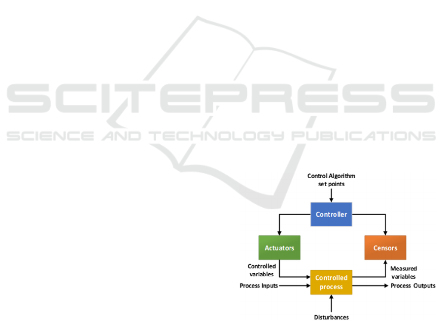
A hierarchical safety control structure is used in
STAMP to represent the system and control loops in
it (a typical control loop is presented in Figure 1),
showing how constraints are enforced. Instead of
addressing accidents as the results of an event-chain,
they are considered to result from a lack of constraints
on behaviour at each level of a socio-technical
system. The design of the initial system needs to
impose appropriate behavioural constraints to ensure
safe operation (Leveson & Thomas, 2018).
Figure 1: Typical Control Loop.
2.2 STPA Hazard Analysis Model
STPA is based on system control theory and not on
reliability theory established in most existing risk
analysis techniques. The basic principles of STPA are
Hazard Analysis for Decentralized Charging Management of Electric Vehicles
221

the following: (Leveson, 2013); (Friedberg et al.,
2017); (Horne, 2017):
• The best way to detect accident chances in
complex systems is to omit causal factors that are
not stochastic or for which no information is
available. Probabilistic analysis results may not
accurately reflect the actual risks and can be
riskily misleading.
• Unlike traditional risk analysis techniques, STPA
is stronger in identifying risk causes and
hazardous scenarios, especially those related to
system design and human behaviour.
• STPA, supporting hierarchical safety control
structures, can be used for both technical design
and organizational planning.
• STPA can be applied to any emergent system
property in the system engineering and product
lifecycle, apart from safety.
• Because STPA is a top-down approach, system
safety engineering can be used early in the system
development process to create high-level security
requirements and constraints.
Also, STPA analysis can be integrated into the entire
system engineering process resulting in a significant
decrease in the cost of engineering for safety
(Karatzas et al., 2020).
The objectives of this paper are by using the main
principles of this relatively new systemic model in the
proposed EV charging management application to:
- Provide guidance to analysts and detect accident
scenarios that cover the entire accident process
and not just individual components
- Provide the necessary information to guide the
design process, rather than requiring design
configurations before risk analysis begins. STPA
results can then be used to guide architecture,
preliminary and detailed design, make decisions in
the implementation phase and improve control
structure.
3 METHODS AND MATERIALS
3.1 Architectural Design of the System
A prerequisite for the hazard analysis of the system,
is the understanding of its operation and the
interactions between its subsystems, so that to
identify inadequate controls within it. Therefore, it is
necessary to present the basic architecture and the
processes of the electric vehicles within the context
of the charging management application. The
proposed application through the use of a mobile
phone will provide interaction between the EV driver
and Charging Stations (CSs). It will act as a
communication channel between the driver, the
vehicle control unit (VCU) and the Charging Point
Control Unit (CPCU), handling the entire charging
process. The proposed web application consists of
four consecutive phases. In the Identification phase,
an electric vehicle interacts with the application and
submits a request for charging including information
about the region R within it moves, the time horizon
T in which plans to charge, and the desired amount of
energy e. In the Bidding phase, charging stations
within region R, sends one or more offers to a
Distributed Ledger, responding to the user request.
CSs belonging to the R region that are able to respond
to the EV user request make one or more bids B.
Subsequently, during the Selection phase, the
optimum station is selected through a series of
parameters, such as the price of energy, the costs of
travel, the distance between the electric vehicle and
the charging station, as well as other variables entered
as preferences by the EV user. Finally, during the
Charging Phase, the electric vehicle communicates
directly and approaches the selected station for
charging and finalizing the transaction.
The objective function, which will suggest the
optimal solution among the charging points
alternatives, will be composed of the following
parameters: • The cost of energy supply • The cost of
moving the electric vehicle from current location at
the time of request to each potential charging station,
taking into account distance travelled and traffic
conditions using GPS data. • The specifications of the
vehicles (battery capacity, maximum required
charging energy, connection and disconnection times
of electric vehicle). • The status of charging stations
(availability, charging status, billing status).
3.2 STPA Implementation
STPA is a process consisting of four phases with
interconnected activities, thus can be considered as a
repetitive process constantly updated with feedback
from the evolving system design. The individual
phases are briefly presented below.
Define Purpose of the Analysis: The definition of
the purpose of the analysis is the first step in any risk
analysis method. The types of losses that the analysis
intends to prevent, the hazards that emerge, and the
system boundaries are defined.
Model the Control Structure: In the second phase
analysts generate the Control Structure which is a
schematic representation of the system. A control
SMARTGREENS 2021 - 10th International Conference on Smart Cities and Green ICT Systems
222
structure depicts the system as a set of feedback
control loops, including the functional relationships
of subsystems and the interactions with each other.
The control structure usually starts at a very abstract
level and is constantly being developed in depth to
incorporate more details about the system.
Identify Unsafe Control Actions: In the third phase,
the Control Actions (CAs) evolving from the control
structure study, are analysed and examined to
determine the conditions under which they could lead
to losses. Thus, Unsafe Control Actions (UCAs) are
identified and recorded, which in turn are used to
establish a list of functional requirements and
constraints for the system.
Identify Loss Scenarios: In the final phase, STPA
identifies the reasons that unsafe control actions may
occur, and loss scenarios are generated to explain:
• Whether incorrect feedback, inadequate
requirements, design errors, component failures
and other factors could cause unsafe control
actions and ultimately lead to losses.
• How safety control actions can be provided but not
followed or performed correctly, resulting in losses.
Once loss scenarios are identified, they can be used to
create additional Safety Requirements, leading to
updated design proposals, if STPA is used during the
design phase (Leveson & Thomas, 2018).
In the present study, the SafetyHAT modelling
tool, developed by the US National Transportation
Systems Center (Volpe, 2014) is applied for
modelling and mapping the different components as
defined in the STPA methodology. SafetyHAT is
selected due to its simplicity and maturity in relation
with other software tools that support STPA analysis
e.g., A-STPA (Krauss et al., 2015) and XSTAMPP
(Abdulkhaleq et al. 2015).
4 STPA RESULTS
The STPA risk analysis examines the risks of the
proposed web application during its design phase,
regarding the losses that can result from both unsafe
control actions in the individual subsystems, as well
as from their connection and communication.
Specifically, the reported losses may include:
Malfunction of Individual Components:
• Blockchain Technology: Privacy issues (e.g.
disclosure of the electric vehicle location or
energy need).
• Electric Vehicle Supply Equipment (EVSE):
Damaged or modified charging equipment (e.g.,
corrupted Residual Current Device (RCD), a
sensitive safety device which automatically
shuts off the power supply in a fault event for
the protection against electric shock or fire).
• Optimization Algorithm: Errors that lead to non-
optimum decisions regarding the selection of the
charging station (e.g. non-convergence of the
algorithm, errors in algorithm logic).
Communication between Subsystems:
• Interoperability: Compatibility between the
software subsystems and the charging system
(e.g. charging equipment incompatibility,
incompatibility between charging equipment
and distributed ledger technologies).
• Data Reliability: Data collected from
unrecognized source origin (e.g. unreliable user
identification, unreliable timestamp of requests,
unreliable estimation of energy demand,
unreliable price offered by a provider).
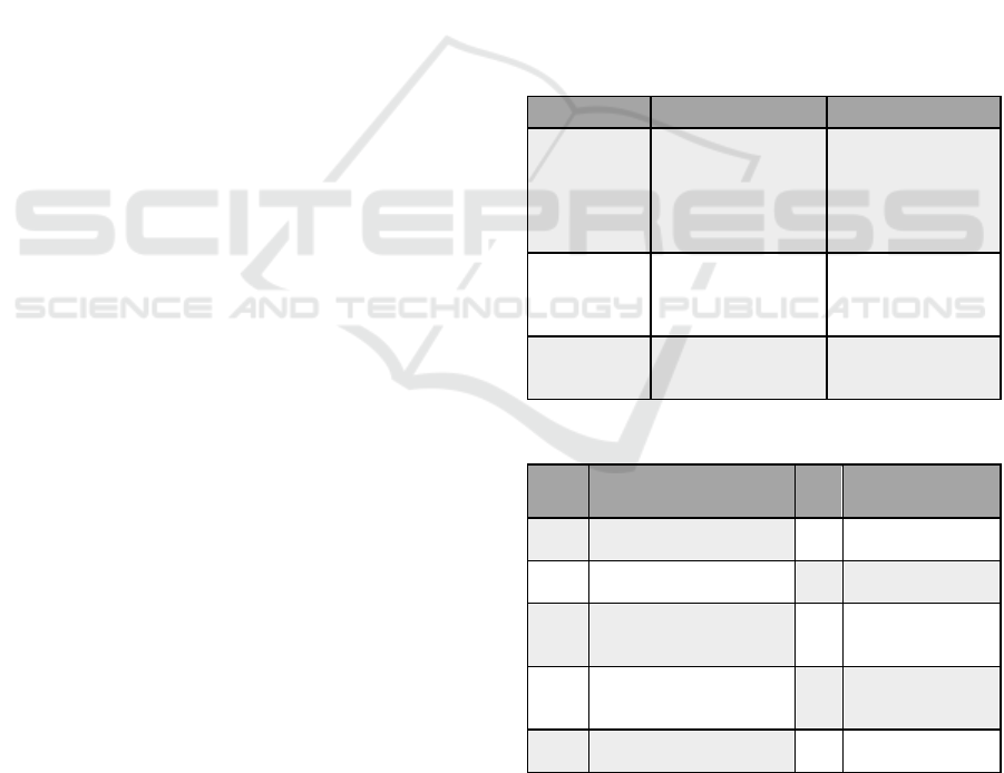
Table 1: Values and objectives of the stakeholders.
Stakeholders Values Goals
EV user
Preferences
Personal data
protection
Data reliability
Transactions security
Equipment integrity
Transfer from point
A to point B
EV Intermediate
Charging
Finding the best
charging option
Application
Ensuring user
privacy
Data reliability
Secure Transactions
Achieving EV -
CS communication
Satisfaction of users
& energy providers
Charging
Stations
Data reliability
Secure Transactions
Equipment integrity
Energy supply
Energy storage
Profit
Table 2: System losses.
Α/Α Losses Α/Α Losses
L-1
Unable to transfer from
AtoB (EV)
L-6 Unreliable data
L-2
Damage or destruction
of EV equipmen
t
L-7 Unsafe transactions
L-3
Unsuccessful
intermediate charging
process
L-8
Unable to supply
energy (CS)
L-4
Inability to satisfy
users & providers
L-9
Damage or
destruction of CS
equipmen
t
L-5
Loss of sensitive
information
L-10 Loss of energy
4.1 Define Purpose of the Analysis
The first task of this step is the recognition of losses,
which is accomplished through the next three steps.
Hazard Analysis for Decentralized Charging Management of Electric Vehicles
223
Step 1: Identification of all stakeholders engaged to
the system under examination, which are the
Electric vehicle EV user, the Application
and the charging station (CS).
Step 2: Recording values and goals of each
stakeholder (Table 1).
Step 3: Induction of their values and goals in
potential losses (Table 2).
The second task includes the definition and setting of
the system boundaries, the recognition of system
hazards at system level and their linkage to the losses
(Table 3). The logic underneath is represented as:
<Hazard Specification> = <System> & <Unsafe
Condition> & <Link to Losses>
The third task is the identification of safety
constraints at system level and their linkage to the
Hazards, as represented in the system logic sentence:
<System-Level Constraints> = <System> &
<Condition to Enforce> & <Link to Hazards>.
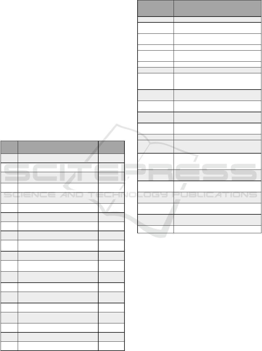
Table 3: Hazard specification.
Α/Α System – Level Hazards Losses
H-1 The EV is not sending request 1,3
H-2 The EV enters incorrect data 1,2,6,9
H-3
The application does not receive
the reques
t
1,3,4
H-4 The application loses data 5
H-5
The application does not transfer the
reques
t
1,3,4
H-6 The CSs do not take the request 1,3,4
H-7 The CSs do not send bids 1,3,4
H-8 The CSs send incorrect data 1,3,4,6,9
H-9 The application does not receive bids 1,3,4
H-10
The application does not provide an
optimal choice
3,4,6
H-11 The EV is not commit best bid 1,3,4,6,8
H-12
The CS does not receive
the commitment
1,3,4,6,8
H-13
The application does not transfer the
commitment & navigation plan
1,3,4,6,8
H-14 The EV does not reach the selected CS 1,3,4,6,8
H-15
The CS does not verify the
commitment
1,3,4,6,7,8
H-16 The EV cannot get charged 1,3,4,8
H-17
The EV is not satisfied upon the
reques
t
2,3,4,6,7
H-18 The EV is damaged 2,4
H-19 The CS is not satisfied upon the offer 3,4,6,7,10
H-20 The CS is damaged 9,10
Table 4: Control actions and feedback.
Control Action
/
Feedback
Description
Reques
t
The EV use
r
submit request for charging.
Request
Transmission
The Distributed Ledger transmits
the reques
t
to the CSs.
Request
Processing
CSs in the R area test whether they can
satisfy it.
Bidding CSs make one or more bids.
Bid
Ttransmission
Bi is transferred from CS to EV.
Optimum bid The application sorts the available bids.
Selection EV user selects the optimum CS
Commitment
The EV user confirms CS booking by
sending a commitment request to the
application.
Commitment
Transmission
The application forwards the commitment
request to the selected CS.
Commitment
Verification
The selected CS accepts the commitment
request.
Smart
Contrac
t
A smart contract is drawn up between the
user and the CS.
GPI
Navigation
EV user is navigated to the selected CS.
Driving The EV use
r
drives to the selected CS.
Commitment
Confirmation
The commitment and timestamp are
confirmed upon EV arrival at the CS.
Connection
Confirmation
If both the commitment and the timestamp
are valid, CS allows the connection with
the EV.
Energy
transmission
The energy e is transferred from CS to EV
as agreed in the contract.
Charging
Completion
CS shuts off the energy supply.
Payment
Reques
t
CS sends a request to the EV user to
submit the payment.
Payment
The EV user pays the amount agreed in the
contract.
Payment
Confirmation
The CS confirms that it has received
payment from EV.
Release The CS releases the EV.
For example, for the H-1, the corresponding
safety constraint SC-1 is that the EV must send a
request.
4.2 Control Structure Modelling
The control structure consists of functional Blocks
connected by downward arrows representing Control
Actions (CAs), as well as upward arrows symbolizing
the Feedback). The gradual addition of data to the
control structure makes it easier for both the reader to
understand and accept the control structure of the
system and the analyst himself to avoid hasty
decisions and connections. Based on the above, it is
understood that each system, no matter how complex
or simple, does not have a unique control structure, as
it depends on the level of modelling.
SMARTGREENS 2021 - 10th International Conference on Smart Cities and Green ICT Systems
224
The modelling starts at a high level, where it
includes the subsystems and the connection between
them (Figure 2) and continues at lower levels, in
which additional details for the design of the system
are additionally incorporated.
Figure 2: High level control structure with subsystems.
The control actions of the controllers and the
corresponding feedback in each control loop is
extracted and presented in Table 4.
4.3 Recognition of Unsafe Control
Actions
During this task the Unsafe Control Actions (UCAs)
for each control action are determined, through which
subsequently the Controller Constraints are defined.
There are four ways in which a Control Action (CA)
can become unsafe which are represented by the
following phrases (Leveson & Thomas, 2018):
• Control Action Not Provided
• Control Action Provided incorrectly
• Control Action Provided Too early / Too late / Out
of order
• Control Action Stopped too soon / Applied too
long)
There has been identified a non-exhaustive list of 64
unsafe control actions by following the structure:
<UCA Specification>:<Source> <Type> <Control
Action><Context><Link to Hazard>
and are organized into a table by control action, (an
example shown in Table 5) which contains an
indicative list of CA and UCAs. Controllers
constraints, consequently, arise as countermeasures
to unsafe control actions.
Table 5: Unsafe Control Actions.
Control Action
- CA
Not Provided Provided incorrectly
Provided Too early / too
late / Out of order
Stopped too soon /
Applied too long
Request
[ UCA -1]:
The application does
not secure the user's
personal data [L4, L5,
L6]
[ UCA -5]:
The user does not submit the
various parameters correctly
[L1, L2, L3, L8]
[ UCA -8]: The user sends
the request too late
[L1, L4, L8]
[ UCA -9]:
User stopped the submission
process early and the request
was not sent to the application
[L1, L3, L4]
Bidding
[ UCA -15]:
The CSs does not
process the request
[L3, L4, L8]
[ UCA -17]: The CSs does not
correctly estimate the available
energy capacity, availability or
compatibility with EV. [L1,
L2, L3, L4, L8, L9, L10]
[ UCA -19]:
The CSs submit bids before
checking available energy
capacity, availability or
compatibility [L1, L2, L3,
L4, L8, L9, L10]
[ UCA -22]: The CSs submit
bids with excess delay [L3,
L4]
Selection
[ UCA -24]:
The application
algorithm does not
send the bids
hierarchical lis
t
[L1, L4]
[ UCA -26]:
The user does not select
correctly from the bids list [L1,
L3, L4]
[ UCA -28]: The user
selects too early without
anticipating all bids from
CSs [L3, L4]
[ UCA -31]: User stopped the
process early and no CS was
selected [L3, L4]
Payment
[ UCA -56]: User does
not pay [L4, L7]
[ UCA -57]:
The user does not deposit the
correct payment amount [L4,
L7]
[ UCA -59]: The user pays
without completing the
charge [L1, L7, L8, L10]
N/A
Table 6: Loss Scenarios.
Unsafe Control
Action - UCA
Loss Scenario - LS Loss Scenario Type
[UCA-1]:
The application does not secure
the user's personal data
[LS-1]: The Distributed Ledger of the application
receives the EV user's personal data correctly but
manages it incorrectly, disrespecting the EV user
privacy
The auditor receives correct feedback /
information, but misinterprets or
ignores it
system
CS
subsystem
Web App
subsystem
EV
subsystem
Control actions
feedback Input / Output
Hazard Analysis for Decentralized Charging Management of Electric Vehicles
225
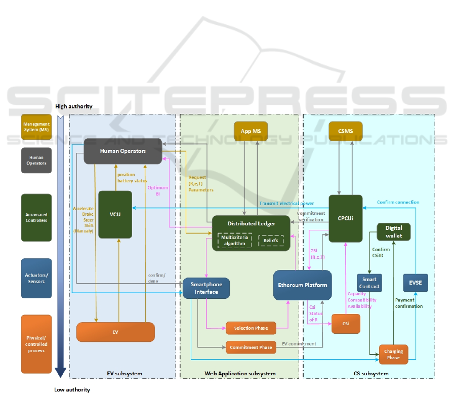
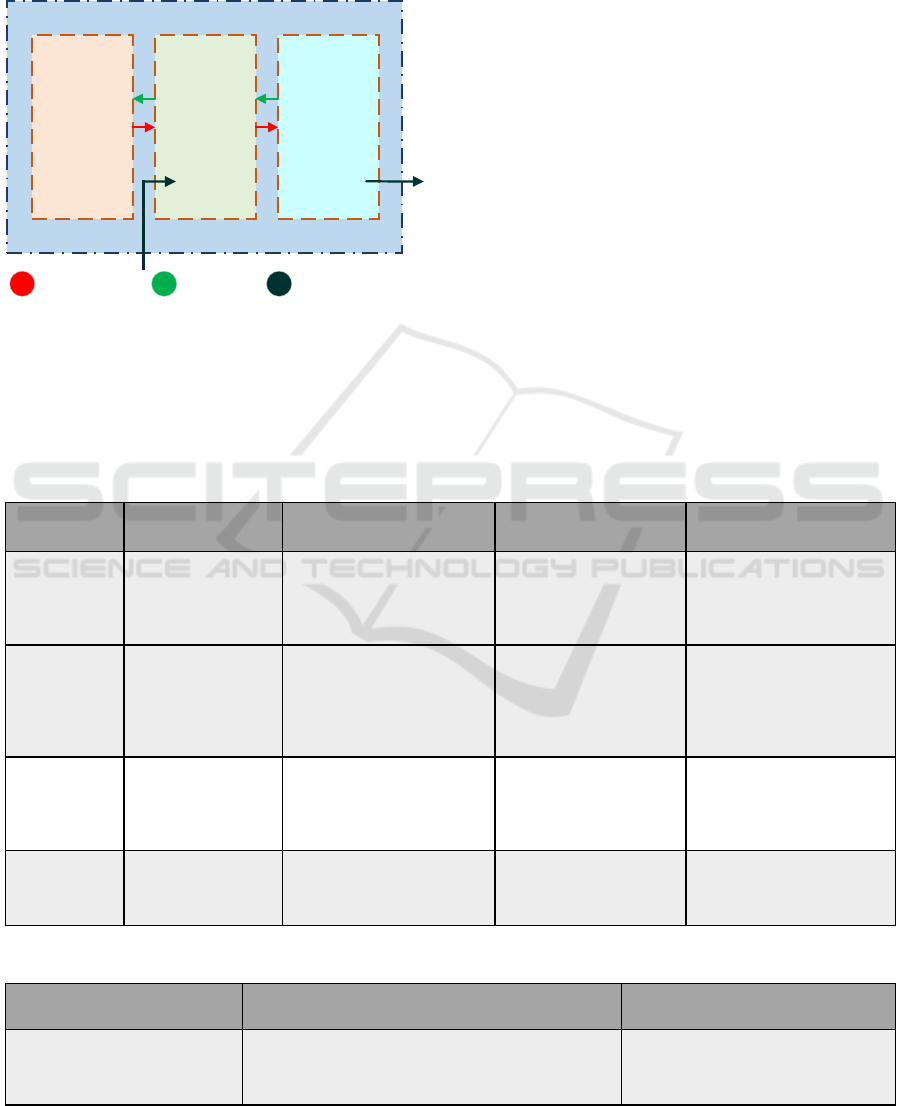
4.4 Detection of Loss Scenarios
At fourth step the loss scenarios are defined, by
answering (Leveson & Thomas, 2018):
(a) Why do unsafe controls occur?
(b) Why are the control actions performed improperly
or not at all, leading to risks?
The process that the feedback is detected (e.g. with
sensors) and control actions are performed (e.g. with
actuators) is added through the reformation of the
control structure (Figure 3).
Based on this structure, scenarios leading to
unsafe control actions are initially identified,
indicatively depicted in Table 6.
This type of script can be created starting with a
UCA and working backwards to explain what might
cause the controller to provide (or not provide) this
control action. To create scenarios that include UCAs,
the causal factors (CFs) responsible for the unsafe
behaviour of the controller that triggered the UCA
must be considered. . In this process, CFs are the main
reasons that can lead control actions to become
UCAs. Following the CFs identification, and in order
to provide information on how to reduce the CF-
related risk associated with UCAs, the next step is to
identify appropriate “safeguards” for each CF. The
safeguards are actions required to either prevent the
causal scenario from occurring or reduce the impact
on the scenarios perceived by the relevant CF
(Karatzas et al., 2020).
5 RESULTS, DISCUSSION AND
CONCLUSION
The results of hazard analysis are the scenarios losses
which can be used to develop additional safety
requirements, define new safety constraints or
improve existing ones, and guide systems redesign
decisions before the actual development of the
proposed application. Through STPA
implementation, general observations have been
made:
• The STPA steps facilitates the work of the
analysts without strong experience in system
design.
• The control structure scheme contributes to a
better understanding of the system functional
characteristics and consequently to the
identification, visualization and confrontation of
operational performance gaps.
Figure 3: Control structure with actuators and sensors.
SMARTGREENS 2021 - 10th International Conference on Smart Cities and Green ICT Systems
226

• The gradual integration of information into the
control structure allows the smooth transition of
the reasoning process from an abstract schematic
representation to more detailed ones, avoiding
hasty and possibly unfounded conclusions of
analysts.
• The schematic representation of the control
structure of complex systems, as well as the
recording of the basic concepts for each step due
to the large extent of the tables, can sometimes be
challenging. This complexity issues are mitigated
with the use of software tools such as SafetyHAT.
Since the STPA method focuses on defining system-
level hazards, while there is no practical or reliable
way to assess each of the reported UCAs or
safeguards. The major advantage is that having the
whole system view can help in the hazard assessment
process when attempting to comprehend and evaluate
the efficiency of control measures. This mechanism
is useful in understanding where gaps in current
operational structures may exist and in implementing
targeted strategies through standard approaches of
risk assessment. This point is reinforced by the fact
that while there is potential for evolution in risk
management frameworks that place higher stress on
risk controls, such operational hazard assessment
methods in providing these controls still does not
exist (Karatzas et al., 2020).
The suggested method encourages analysts to
begin by studying an abstract control structure, which
is gradually redefined by incorporating more
information, such as the input of actuators and sensors
into each control loop, it is expected that with each
deepening the analysis improves. The analysis
conducted in this paper are basic prerequisites for the
redesign of the proposed charging application, in
order to correct the identified blurred points and avoid
losses during its actual development.
FUNDING
“This research is co-financed by Greece and the
European Union (European Social Fund- ESF)
through the Operational Programme «Human
Resources Development, Education and Lifelong
Learning 2014-2020» in the context of the project
“Development of Dynamic Pricing and Autonomous
Trading Application for Electric Vehicle Charging in
the Digital Energy Market context” (MIS 5047183).”
REFERENCES
Abdulkhaleq, A. & Wagner, S., 2015. XSTAMPP: An
eXtensible STAMP Platform for Safety Engineering. In
2015 STAMP Workshop, MIT, Boston, USA.
Friedberg, I., Mclaughlin, K., Smith, P., Laverty, D., &
Sezer, S., 2017. STPA-SafeSec: Safety and security
analysis for cyber-physical systems. In Journal of
Information Security and Applications, 34, 183-196.
Hollnagel, E., & Goteman, O., 2004., The functional
resonance accident model. In Proceedings of cognitive
system engineering in process plant, 155-161.
Hollnagel, E., 2004. Barriers and accident prevention,
Burlington, Hampshire, England, Burlington, VT:
Ashgate.
Horney, D., 2017. System-Theoretic Process Analysis and
Safety-Guided Design of Military Systems, M.S.
Thesis, MIT, Cambridge, MA (USA).
Karatzas S, Chassiakos A. System-Theoretic Process
Analysis (STPA) for Hazard Analysis in Complex
Systems: The Case of “Demand-Side Management in a
Smart Grid”. Systems.2020;8(3):33.
Krauss, S., Rejzeka M. & Hilbesa C., 2015. Tool
qualification considerations for tools supporting STPA.
In Procedia Engineering, 128, 15-24.
Leveson, N. & Thomas, J. ,2018. STPA Handbook, MIT
Press, Massachusetts, USA
Leveson, N., 2004. A new accident model for engineering
safer systems. In Safety Science, Vol. 42, pp. 237 – 270
Leveson, N., 2012. Engineering A Safer World: Systems
Thinking Applied to Safety, MIT Press, Cambridge,
MA.
Leveson, N., 2013. An STPA Primer, MIT Publication.
Ouyang, M., Hong, L., Yu, M. H., & Fei, Q., 2010.
STAMP-based analysis on the railway accident and
accident spreading taking the China-Jiaoji railway
accident for example. In Safety Science, 48:5, pp. 544-
555.
Qureshi, Z., 2008. A Review of Accident Modelling
Approaches for Complex Critical Sociotechnical
Systems, Defence Science and Technology
Organisation (DSTO), Australia.
Thomas, J.; Leveson, N.G., 2011. Performing hazard
analysis on complex, software and human-intensive
systems. In Proceedings of the 29th ISSC Conference
about System Safety, Las Vegas, NV, USA.
Volpe, The National Transportation Systems Center, 2014.
Transportation Systems Safety Hazard Analysis Tool
(SafetyHAT), Cambridge, MA.
Wienen, H. C. A., Bukhsh, F. A., Vriezekolk, E.,
&Wieringa, R. J., 2017. Accident Analysis Methods and
Models - a Systematic Literature Review, Centre for
Telematics and Information Technology (CTIT),
Technical Report No.TR-CTIT-17-04.
Hazard Analysis for Decentralized Charging Management of Electric Vehicles
227
