
Electronic Circuits Extrinsic Evolutionary Platform
Pedro Henrique Gouvea Coelho, J. F. M. do Amaral and M. C. Bentes
State Univ. of Rio de Janeiro, FEN/DETEL, R. S. Francisco Xavier, 524/Sala 5001E, Maracanã, R. J., 20550-900, Brazil
Keywords: Genetic Algorithms, Artificial Intelligence Applications, Evolutionary Electronics.
Abstract: This paper presents an electronic circuit evolution platform based on genetic algorithms with different
modes of operation. The platform has an extrinsic structure for evaluating individuals, making calls to a
circuit simulator for each possible solution evaluated. The platform can perform evolutions in search of
values for components, additional topologies to a fixed circuit and a search with total variation in the types
of components, values and connections. The assessed fitness can be based on a single objective, evaluating
only the output of the circuit, but also based on several objectives. The chosen method for this quantification
of multiple objectives is based on a Fuzzy System in order to facilitate the designer's specification. The
evolutions can be carried out in the time domain as well as in the frequency domain, being possible for the
user to change the operating mode without changes in the code already created. The exchange between the
operating modes, inputs used and the use of functions present on the platform is performed directly through
configuration variables, without the need to change the source code of the platform. In order to verify the
performance of the platform, each mode can be evaluated using different circuits with varying complexities.
Some selected case studies are shown in the paper to corroborate the feasibility of the method.
1 INTRODUCTION
With the advancement of technology in the area of
electronic engineering, the devices had their
processing capacity expanded and the space required
for implementation was reduced. This made it
possible for the equipment to become smaller and
smaller and with greater performance. Due to this
miniaturization capacity and high performance,
electronic devices have been used in a dedicated
way in the most diverse applications. Such devices,
known as Embedded Systems, allow to aggregate in
a single piece of equipment all the processing
necessary to perform a certain action. The additional
tools that a device can contain range from basic
diagnostic systems to additional tools to the
functions performed by the device. Whatever the
addition to the basic system, all aim to improve the
user experience by requiring minimal user
interference and integrating with other systems used.
The separation of systems into parts dedicated to a
specific task (modules) makes it possible to more
easily identify defective divisions and carry out
replacement more quickly. Such separation also
makes it possible to update the system by replacing
one module with another with superior performance.
However, despite facilitating the repair and updating
of systems, this segmentation does not seek to solve
any internal flaws. Such an approach considers the
use of devices until the appearance of failures and,
consequently, disposal of the defective module and
replacement with another with appropriate behavior.
Thus, this methodology directly affects the negative
technological impact on the environment,
contributing to the increase in electronic waste. In
addition to the concern with the environmental
impact of the accelerated disposal of devices, there
are applications that do not allow an easy
replacement of the modules. Applications in the
areas of space exploration and oil exploration
demand solutions to functional failures in a fast and
automatic way, due to the cost and complexity
associated with any required repair. For such
applications, a tool is sought that, associated with
the functioning of the devices, is able to circumvent
or mitigate the problems caused by any defective
part. This search comprises a specific line of study.
In order to enable adaptability to devices, a line of
research called Evolutionary Electronics (Haddow
and Tyrrell, 2018) can be used. This line of research
is based on the Evolutionary Computing technique,
which is inspired by Darwinian Evolution for
752
Coelho, P., M. do Amaral, J. and Bentes, M.
Electronic Circuits Extrinsic Evolutionary Platform.
DOI: 10.5220/0010480307520759
In Proceedings of the 23rd International Conference on Enterprise Information Systems (ICEIS 2021) - Volume 1, pages 752-759
ISBN: 978-989-758-509-8
Copyright
c
2021 by SCITEPRESS – Science and Technology Publications, Lda. All rights reserved

problem solving (Coello, 1999) (Coello, 2013)
(Labati et. al., 2016). The application of this
research, used in self-repair, seeks to evolve the
functioning of electronic circuits in an autonomous
way (Sinohara, 2001) (Santos et. al., 2012). This
paper is organized in four sections. The second
section describes the basics of evolutionary
environment and the proposed platform. Section
three discusses case studies in connection with the
evolutionary circuits platform. Finally section four
ends the paper with the conclusions.
2 EVOLUTIONARY STRUCTURE
2.1 Evolutionary Electronics
Along with the application of Computational
Evolution in the area of Electronics Engineering a
new line of research has emerged. This line of
research is called Evolutionary Electronics. In this
line of research, evolution is carried out through the
evaluation of electronic circuits and the objective is
to evolve such circuits until the desired specification
is obtained. (Greenwood and Tyrrel, 2007) (Reorda
et. al., 2017). To carry out the evolution of these
circuits, the same operators and the operating logic
used in Evolutionary Computing are used. However,
these characteristics must be adapted for this type of
evolution. When using Genetic Algorithms in the
evolution of circuits, the evaluated individuals are
the circuits instead of numerical solutions as in
Evolutionary Computation. The representation of
each individual is adapted to represent a specific
characteristic of circuits, a characteristic that will be
the target of the evolution process. The concepts of
population and generation are transported from one
line of research to the other without any change in
meaning. For both lines of research, the population
of individuals represents a set of possibilities or
representations for the target characteristic of
evolution. In the evolution of circuits, circuit
topologies evolve. This characteristic may vary
according to the designer, and may, for example,
represent the value of components or their tolerance.
Once the characteristics of a set of solutions are
determined, such individuals can be evaluated and
selected by the process responsible for assessing the
suitability of each possible solution or selection.
This selection and modification of the next
generation is then performed in an iterative way up
to the stopping criterion previously established for
the evolved circuit. This criterion can be used to
evaluate the response observed by the circuit or the
time required for the process, that is, a maximum
number of cycles or generations available for the
search process. The operators responsible for
modifying the population (set of solutions) will
exhibit the same behavior previously presented,
behavior responsible for the efficiency of the
method. The combination operator (Crossover) will
be responsible for merging the representations in
search of a better performing solution. The rate of
the population that will perform the combination
directly affects the speed of evolution, as it
determines the speed of variation observed in each
search cycle. The mutation process will be carried
out on the combined individuals, attributing a
random character on the evolved characteristic. This
allows evolution to discover promising
characteristics without restricting those belonging to
the generating individuals. Thus, the understanding
of the evolution of a topology through Genetic
Algorithms is interchangeable with the way that a
population becomes immune to a disease through
Natural Evolution. Once the operation mode for the
evolution of circuits has been defined, the Genetic
Algorithm can be inserted in platforms dedicated to
the evolution of circuits. Such platforms are called
Evolutionary Platforms and are classified according
to their mode of operation. Evolutionary Platforms
can be used to act on circuits and adapt them in the
event of faults. In this type of application,
reconfigurable platforms are able to restructure their
connections and devices used to achieve a desired
response, an answer that can be analog or digital.
These platforms are classified according to the type
of project carried out, the nature of the evolved
project and the operating structure of the platform.
The type of project carried out is classified
according to the objective of the evolution carried
out. This objective can be the optimization of an
existing circuit or the synthesis of a circuit topology
that satisfies a certain desired output. The
classification of the nature of the project refers to the
nature of the evolved topology. This nature
corresponds to the type of quantity observed at the
topology output and assesses whether the circuit has
an analog or digital output. These platforms are
classified according to the type of project carried
out, the nature of the evolved project and the
operating structure of the platform. The type of
project carried out is classified according to the
objective of the evolution carried out. This objective
can be the optimization of an existing circuit or the
synthesis of a circuit topology that satisfies a certain
desired output. The classification of the nature of the
project refers to the nature of the evolved topology.
Electronic Circuits Extrinsic Evolutionary Platform
753
This nature corresponds to the type of quantity
observed at the topology output and assesses
whether the circuit has an analog or digital output.
Regarding the operating structure, the classification
observes the evaluation method performed by the
platform. The evaluation of circuits can be carried
out internally or externally to the application
platform. When the evaluation process is carried out
internally, individuals are loaded directly onto the
platform and the suitability of each representation is
given by observing the response obtained when
leaving the platform. This type of platform receives
the classification of Intrinsic Platform. Such
technique guarantees an aptitude value perfectly
compatible with the final performance of the circuit,
since this aptitude is evaluated directly on the
hardware platform where the topology will be
applied. On the other hand, the assessment of
individuals can be performed outside the platform
where the topology will be applied. This evaluation
mode uses circuit simulators to evaluate the response
of each topology and assigns the fitness value
according to the simulated performance of each of
the representations used. This type of assessment
does not have an aptitude assessment as reliable as
the assessment of Intrinsic Platforms. However, the
use of simulators in the evaluation guarantees a
more flexible assessment of each evolved topology,
being more appropriate for experimentation.
Platforms with evaluation using simulators are given
the name of Extrinsic Platforms, that is, outside the
platform where they will be used. Thus, the mode of
operation of Intrinsic and Extrinsic platforms differs
only in the way of evaluating individuals of
evolution. Works focused on accurate knowledge of
the response after implemented, instead of a
simulated approach, normally use Intrinsic
Platforms. In this type of work, the system must
have a permanent interface with microcontrolled
hardware for the exchange of information.
2.2 Evolutionary Platform
The choice of the environment used in this paper
focused on the development of a platform that was
able to evolve topologies that used commercial
component values. In this way, the evaluation
process can be carried out in an agile way and the
response observed by the topologies is very close to
the actual response observed. The developed
platform consists of an extrinsic platform whose
circuit simulation will be performed externally by a
specific simulator. The chosen simulator was the
LTSpice XVII, developed by the integrated circuit
manufacturer Linear Technology Corporation, which
is now part of the multinational Analog Devices.
This choice is justified by the fact that it is a globally
used and distributed simulator, available for both the
Windows operating system and the MAC, and
because it is a free distribution software, not
requiring a license for its operation. The platform
will carry out the evolution of analog circuits, that is,
it will be a platform of an analog nature. In addition
to the classification as to the nature of the observed
response, there is a classification as to the nature of
the process carried out. As will be presented, the
platform will have three modes of operation. As the
platform evolves component values, it will be
classified as a topology synthesis platform. The
classification of topology synthesis is also given to
the way in which a complete change of components
and connections is carried out in order to obtain a
satisfactory topology. In the component addition
mode, there is an initially fixed topology that should
be improved by adding components. This mode that
seeks to correct the operation of a topology is
classified as a platform of an optimization nature.
The platform used for programming and,
consequently, responsible for making calls to the
simulator and operating the algorithm was
MATLAB, including GAOT (Genetic Algorithm
Optimization Toolbox). The communication
between GAOT, contained in MATLAB, and the
circuit simulator is carried out through netlist files,
that is, description files of circuit connections. In
this way, MATLAB will create the files with the
topologies to be tested and will read the files with
the sampling resulting from the simulation process.
So MATLAB will adjust the evolution parameters
and also exchange information between the Genetic
Algorithm - GAOT and the circuit simulator -
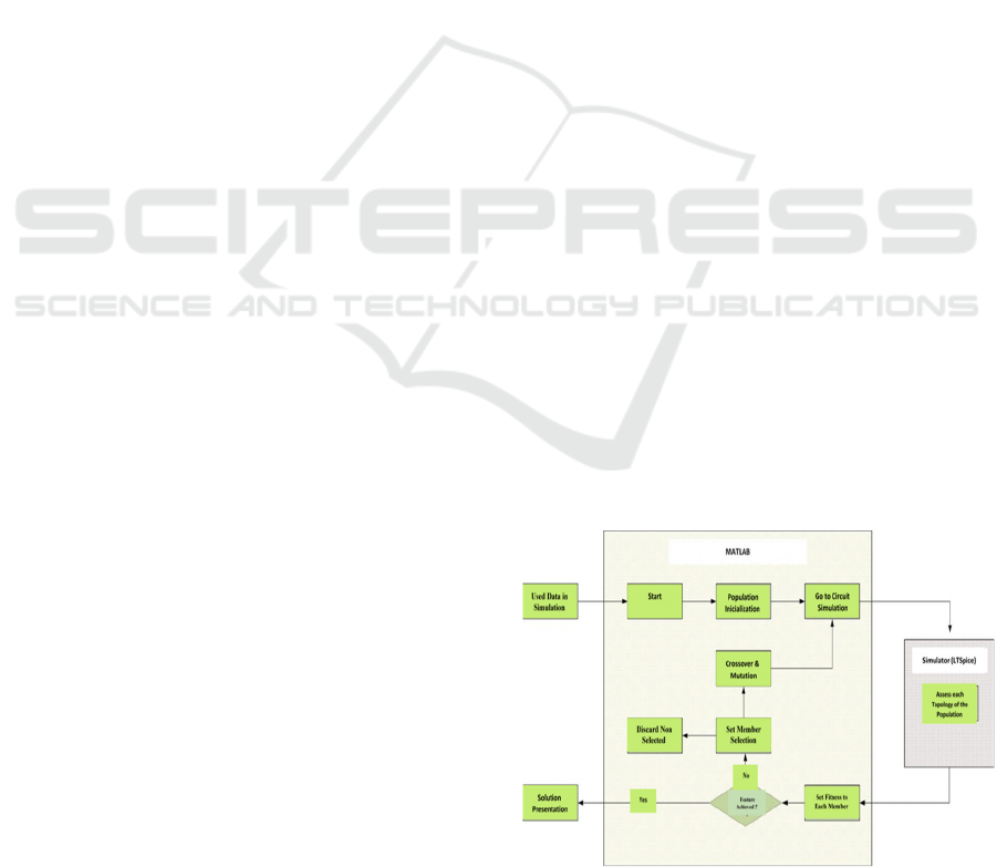
LTSpice. A structure of the developed platform can
be seen in Figure 1.
Figure 1: Flowchart of operation of the developed
platform.
ICEIS 2021 - 23rd International Conference on Enterprise Information Systems
754

The fitness function to assess the evolutionary
adequacy is defined in equation 1 and 2.
(1)
(2)
In the chosen formula, the error between the desired
output and the output obtained by the evolved circuit
is considered in module and on average. Such an
assessment was used to ensure that the individual
value of each sample is considered as the final value,
preventing positive error values from being offset by
negative error values. Once the error is considered in
module, the suitability value will be a value between
zero and one. This restricted range of fitness allows
the use of both the roulette selection method and the
standardized selection method available by the
evolution algorithm used as a basis. In order to
connect the LTSpice simulator to MATLAB, calls
are made to the simulator in the background.
Simulator calls are made in the background for each
simulated circuit. Making calls in the background
frees the user from successive interventions in the
course of evolution. This type of call to the
simulator also allows the user to focus and monitor
the progress of the evolution. The simulator, despite
having a graphical interface, will use a text file
called netlist. Netlist files are simplified text files
that contain the representation of electrical circuits.
In these files, components are specified, their
respective values, the nodes to which they are
connected and basic syntax rules that define
simulation characteristics. MATLAB, the main
language used in the development of the system,
uses this standardized characteristic of the netlist
files to create them and transmit them to the circuit
simulator. The different topologies will be evaluated
according to their different characteristics and used
syntaxes.
2.2.1 Modes of Evolution of a Circuit
The developed platform has three evolution modes.
Each mode of operation will have a specific type of
chromosome and, consequently, a proportional
search space. The choice of the mode of operation
and the supply of the variables corresponding to the
mode are made before the execution of the evolution
process.
The first option is the Component Variation
evolution mode which is used in cases where the
topology to be evolved is fixed and only the value of
the components is evolved. In this evolution mode,
the user informs the fixed topology to the evaluation
function and the types of components used and the
evolution will seek the best set of values for the
desired output. In this evolution mode, the search
space is minimized since it is composed only by the
values of the components used.
The Component Add evolution mode is used in
cases where there is an initial fixed topology and the
evolution algorithm will add components to that
topology, with the goal of achieving the desired
output. In this evolution mode, the user informs the
topology attached to the evaluation function and the
types of components used. From there evolution will
seek a complementary topology that approaches the
desired output. The fixed topology will consist of a
structure similar to the first option -Variation of
components. The type of each component, defined
together with the fixed circuit, will also be used in
defining the new components added. After writing
the fixed circuit, the evolution algorithm will add
elements to it, up to a maximum number of elements
defined by the user before the evolution process. The
search space is considerably larger than the previous
mode. This increase in the search space is due to the
fact that positioning nodes are part of the evolution.
The last mode considered in this paper is the
Complete Variation evolution mode which is used in
cases where the user wants to perform a complete
evolution in search of a solution. In this mode, the
user informs the maximum number of components
to be used and the maximum number of nodes to
which these components must be connected. These
variables, together with the variables already used in
previous modes, such as the amount of component
values available, will determine the evolution to be
performed. From there, evolution will seek a
complete topology, which should approach the
desired output. The type of each component, as in
the previous modes, is defined by the user at a time
before the execution of the evolution. Based on the
types of components made available to the
algorithm, it will perform a complete evolution of
the topology, changing even the node defined as the
circuit output.
3 CASE STUDIES
After a discussion and considerations aspects
involving the development of the platform, case
studies were carried out to verify its operation. Such
analysis will be performed for each of the operating
modes that make up the platform and evaluated
1
1
Fitness
error
=
+
1
() ()
N
Goal Observed
i
Output i Output i
error
N
=
−
=
Electronic Circuits Extrinsic Evolutionary Platform
755
according to the complexity of the circuits used. For
all case studies, the crossover rate used was 85%. A
large number of case studies were carried out from
which 3 were selected.
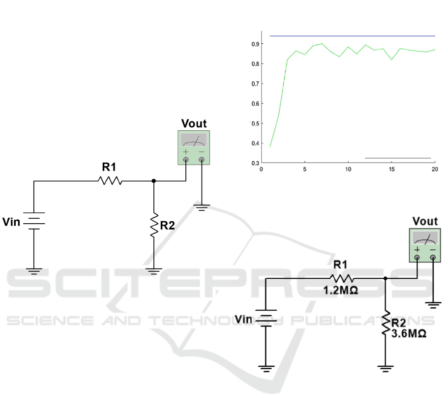
3.1 Case Study 1: Voltage Divider
The first circuit evaluated by the platform was a
basic voltage divider circuit. This circuit, seen in
Figure 2, will be used to confirm the platform's
operation and verify the impact of certain variables
on the evolution process.
Figure 2: Voltage divider circuit.
This evaluation will be carried out for the three
modes that make up the developed platform. Once
performed, it is possible to increase the complexity
of the evolved circuits and verify the evolution
behavior performed by the platform.
3.1.1 Evolution by Variation of Values
The first evolution was carried out in the variation
mode of component values where fixed values were
assigned to the parameters related to selection and
mutation and the evolution of individuals over the
generations was observed. The used parameters were
20 generations with 25 individuals. The crossover
rate was fixed at 0.85, the same as for the other
evolutions, and the selection rate for geometric
normalization and the mutation rate are fixed. Such
an evolution can be seen in Figure 3. Figure 4 shows
the topology obtained using 7 generations of 5
individuals.
3.1.2 Evolution by Adding Components
The evolution by Adding Components is used for
cases in which there is a fixed circuit in operation,
but in which the response does not correspond to the
desired one.
Figure 3: Evolution Using Fixed Mutation and Selection.
Figure 4: Topology Obtained Using 7 Generations of 5
Individuals.
Such an evolution mode can be understood as an
evolution to failures, in which an unwanted response
is observed in a circuit and the evolution algorithm
must add components to this circuit in order to
improve it. In the evolution of the voltage divider
topology, a resistor burn is simulated, which is no
longer part of the circuit (open circuit) and,
consequently, influences the obtained output. From
there, the algorithm will add components to the
topology and evaluate the addition in the presented
answer. At the end of the evolution, an additional
topology is sought that approximates the post-fault
response of the circuit to the previously desired
response. For this evolution a maximum of ten
components and five nodes will be used and all of
them will be resistors. Using the topology that
---------Best Result
-----------Average
OBSERVED FITNESS
GENERATIONS
Simulation History
20 Generations - 93.97 Fitness - 85 Ind.
ICEIS 2021 - 23rd International Conference on Enterprise Information Systems
756
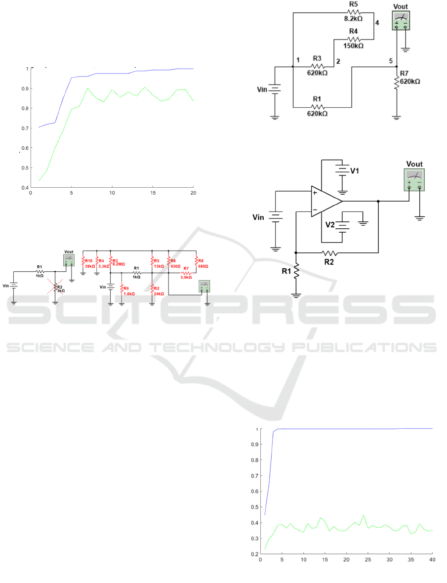
yielded the best performance in the evolution of this
circuit, a compatibility of 99.91% with the observed
response is obtained. This response and the evolved
topology can be seen in Figures 5 and 6 respectively.
Figure 5: Best performance evolution curve for voltage
divider in component addition mode.
Figure 6: Evolved topology for voltage divider in
component addition mode.
3.1.3 Evolution by Complete Component
Change
The next evolution mode corresponds to the
complete component change mode. In this way,
alternative topologies are sought through the
complete variation of the variables in question, that
is, topologies not known directly to the problem.
The topology with the shortest evolution time,
highest performance (Fitness of 100 %) was
considered the best result depicted in figure 7.
3.2 Case Study 2: Amplifier
After performing the evolution for the voltage
divider circuit, the algorithm is used to evolve the
topology of an amplifier circuit. Such evolution aims
to observe if the algorithm is capable of evolving
topologies for more complex circuits. A basic
topology of an amplifier circuit can be seen below in
Figure 8.
Figure 7: Evolved topology for voltage divider in full
evolution mode.
Figure 8: Basic amplifier circuit for case study 2.
3.2.1 Evolution by Variation of Values
The first evolution carried out consists of the
evolution of values of the basic topology of the
amplifier circuit of gain 3. Figure 9 and 10 shows
the evolution curve and the evolved topology
respectively.
Figure 9: Evolution curve for case study 2 – variation of
values.
Observed Fitness
_____
Best Result
______ Average
Generations
20 Generations, Fitness: 99.91 % - 25 individuals
_____ Best Result
______ Average
Observed Fitness
GENERATIONS
40 Generations, Fitness 99,99 %, 65 Individuals
Electronic Circuits Extrinsic Evolutionary Platform
757
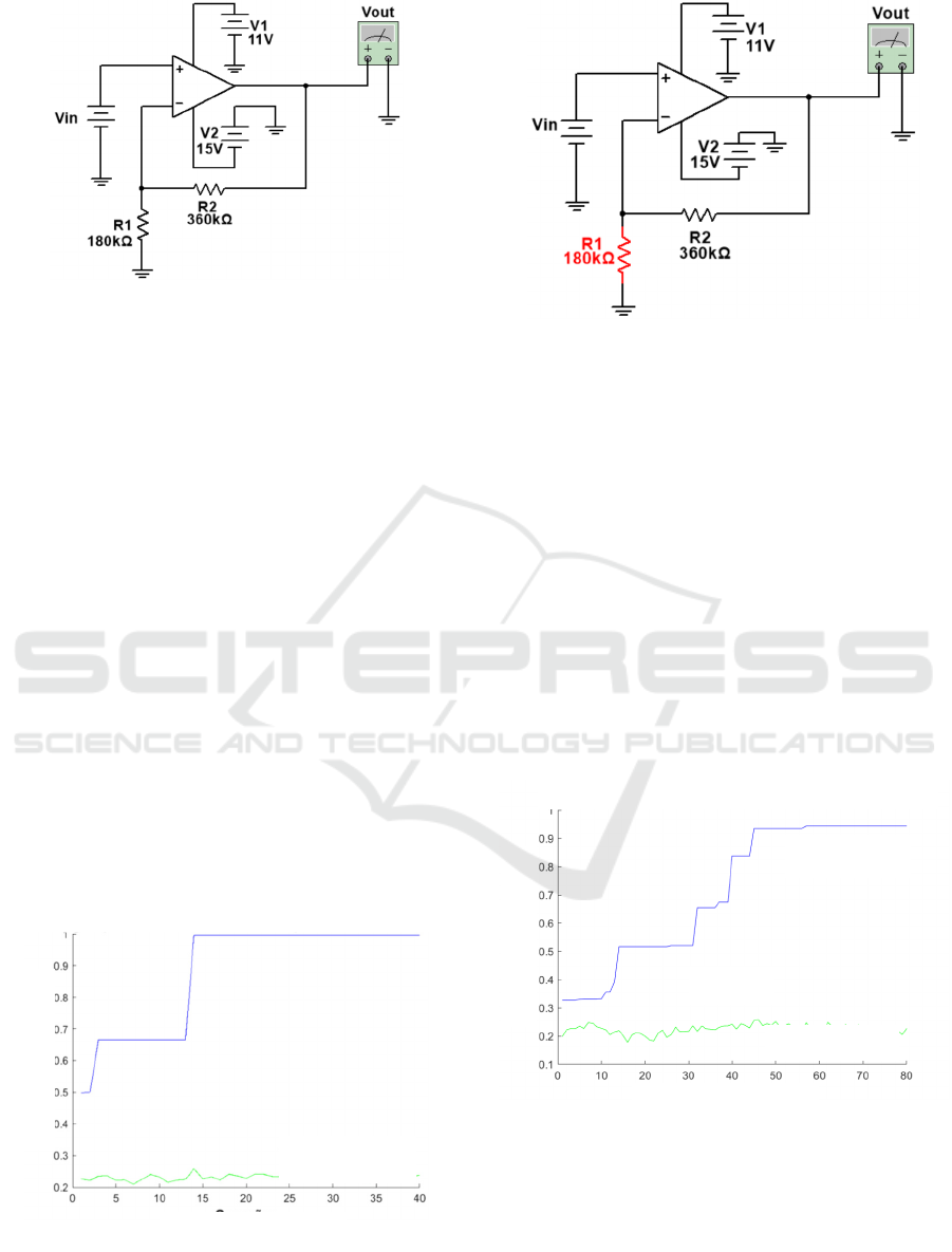
Figure 10: Evolved topology for case study 2 in variation
of values mode.
3.2.2 Evolution by Adding Components
After performing the evolution of a topology for the
amplifier circuit, we will simulate a failure situation
in the evolved circuit. This simulation will test the
platform for a solution to the failure using the
Component Addition mode. The simulated fault will
be the burning of one of its resistors, more precisely
the resistor with a value of 180 kΩ. After the
burning of this resistor, the connection of the nodes
of this component is considered to be non-existent.
From the resulting circuit, the algorithm will add
components to the topology and evaluate such
addition in the observed response. At the end of the
evolution, an additional topology that is capable of
correcting the operation of the amplifier circuit is
sought. It is possible to observe that the evolution
accomplished obtained in response the topology
previously used. Such response was obtained by
adding another resistor with the same value as the
burnt resistor. The evolution curve and the evolved
circuit are depicted in figures 11 and 12 respectively.
Figure 11: Evolution curve for case study 2 – adding
components.
Figure 12: Evolved topology for case study 2 in adding
components mode.
3.2.3 Evolution by Complete Component
Change
After the evolution by adding components, the change in
the Component Modification mode will take place. In this
evolution, the entire topology will be evolved in search of
an adequate solution. This search may not use a starting
solution, which in this case will be the topology evolved in
the evolution of values. The evolved topology and its
observed response at the end of the evolution process can
be seen in Figures 13 and 14 respectively.
It can be seen
that the evolved circuit does not resemble the topology
known for the circuit. However, the output presented by
this topology is very close to the desired one. This
indicates that the platform is capable of searching for
unusual topologies that satisfy a certain desired output.
Figure 13: Evolution curve for case study 2 – complete
components change.
GENERATIONS
___
Best Result
___Average
4
0
G
e
n
e
r
at
i
o
n
s
– Fi
t
n
ess
99.
\
66
–
65
in
d
i
v
i
dua
l
s
G
E
N
ERATI
ONS
80 Generations – Fitness 94.41% - 65
individuals
Best Result
Avera
g
e
Obse
r
ved
Fitn
ess
Obse
r
ved
Fitn
ess
_____
Best Result
______ Average
ICEIS 2021 - 23rd International Conference on Enterprise Information Systems
758
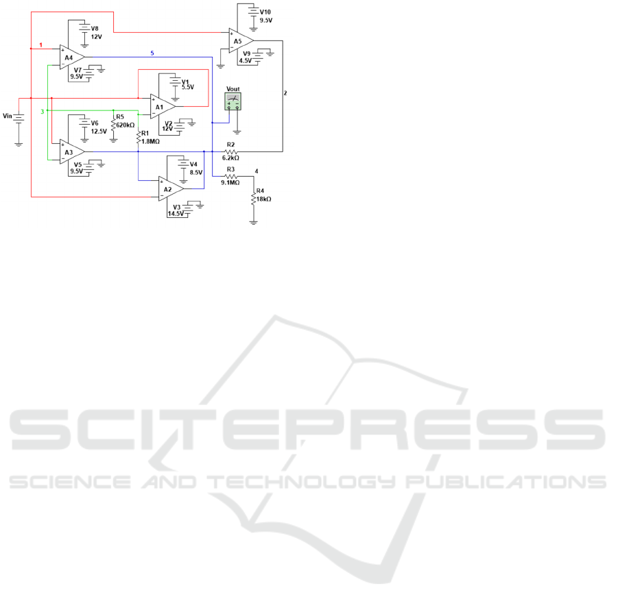
Figure 14: Evolved topology for case study 2 in complete
components change mode.
4 CONCLUSIONS
The results achieved for each of the existing modes
of operation, with different circuits of complexities
and types of different analyzes, indicate good
flexibility for the most diverse experiments. The
designed platform allows the designer to quickly and
easily change the specification of the circuit to be
evolved without complex changes in the code.
Changing the topologies analyzed, the inputs used
and the type of input can be easily modified from the
information passed to the platform. It is the role of
the platform to create the files necessary for
communication with the simulator and the files
resulting from this evolution, without the need for
user interference. In order to optimize the evolution
process, reducing the processing, all case studies
were performed using a virtual disk in the
computer's RAM memory. This type of disk is
called RAM Disk and optimizes the speed of access
and writing of files during accesses. This
optimization occurs because the disk works at the
speed of the respective RAM used, which is
considerably higher than the respective speeds on a
conventional hard drive. Regarding possible future
work it is suggested studies with the objective to
continuously identify faults in circuits. Through this
identification, it would be possible to make
automatic calls to the developed platform and,
consequently, the evolution with automatic circuit
repair from these failures. Another possibility is the
use of topologies evolved in reconfigurable circuits.
In this way, the results evolved by the platform
would be automatically loaded in such circuits and,
consequently, would be available for use in
automatic mode. Based on the performance of
virtualized disks over time another possibility to
further increase performance would be the use of
graphics processing units (GPUs) to optimize the
processing of these circuit evolutions. Such units,
available on video cards, can decrease the time
needed to carry out the evolutions studied in this
paper and in the evolutions of more complex
circuits. The main contribution of the developed
platform is the possibility of changing each
parameter used. Such capacity enables detailed
future studies on the impact of each parameter on the
evolution of circuits.
REFERENCES
Haddow, P. C.; Tyrrell, A. M., 2018. Evolvable Hardware
Challenges: Past, Present and the Path to a Promising
Future. Inspired by Nature, Emergence, Complexity
and Computation 28. Springer International
Publishing.
Santos, F. M. da C., da Silva, I. N ., Suetake, M., 2012. On
the application of intelligent systems for fault
diagnosis in induction machines - An overview, SBA
Control & Automation, v.23, n.5, p.553-569, 2012. (In
Portuguese).
Sinohara, H. T., 2001. Automatic Repairs and
Adjustments of Electronic Circuits Through
Evolutionary Electronics. Rio de Janeiro, Master's
Dissertation (Department of Electrical Engineering -
PUC-Rio). (In Portuguese).
Coello Coello, C. A., 2013. Multi-objective evolutionary
algorithms in real-world applications: some recent
results and current challenges. Advances in
Evolutionary and Deterministic Methods for Design,
Optimization and Control in Engineering and
Sciences, Vol. 36 of the series Computational Methods
in Applied Sciences pp 3-18.
Coello Coello, C. A., 1999. A comprehensive survey of
evolutionary-based multiobjective optimization
techniques. Knowledge and Information Systems,
Volume 1, Issue 3, pp. 269–308.
Labati, R. D., Genovese A., Muñoz, E.. Piuri, V., Scotti,
F., Sforza, G., 2016. Computational intelligence for
industrial and environmental applications, IEEE 8th
International Conference on Intelligent Systems.
Greenwood, G. W., Tyrrel, A. M., 2007. Introduction to
Evolvable Hardware: A Practical Guide for Designing
Self-Adaptive Systems”. IEEE Press Series on
Computational Intelligence. David B. Fogel Series
Editor.
Reorda, M. S, Sterpone, L., Ullah, A., 2017. An Error-
Detection and Self-Repairing Method for Dynamically
and Partially Reconfigurable Systems. IEEE
Transactions On Computers, Volume 66, No. 6.
Electronic Circuits Extrinsic Evolutionary Platform
759
