
Generating Relationship between Design Pattern and Source Code
Mika Ohstuki and Tetsuro Kakeshita
Computing Division, Saga University, Honjo-machi 1, Saga City 840-8502, Japan
Keywords: Educational Support Systems, Software Engineering, Software Process, Design Pattern, Source Code.
Abstract: Software engineers need to learn a variety of knowledge and skills to develop various artifacts, such as
software specification, software design, source code, and test code, during the software process. We are
developing a visualization tool named VRale-SCM for various artifacts and the relationship among them in
VR space. A software engineer can freely navigate the artifacts to deeply understand the artifacts and the
relationship among them. In this paper, we propose a mechanism to generate a relationship between the design
pattern and Java source code. Integration of the proposed mechanism to VRale-SCM will enrich the
educational contents of the system so that the educational effect will be further improved.
1 INTRODUCTION
In today's world, the realization of various services
depends on computer software. With the increasing
sophistication and complexity of software, the
training of advanced software engineers who are
responsible for the life cycle of software, including
planning, development, and operation, is of high
social importance.
The software development process consists of
various processes such as planning, requirements
analysis, design, programming, and software testing
(ISO, 2017). Software engineers need to learn a
variety of knowledge and skills to develop artifacts at
each process.
We are developing a visualization tool named
VRale-SCM for the artifacts of each process and the
relationship among them in VR space (Kishikawa,
2020). A software engineer can freely navigate the
artifacts to deeply understand the artifacts and the
relationship among them. In this paper, we propose a
mechanism to generate a relationship between the
design pattern and Java source code. Integration of
the proposed mechanism to VRale-SCM will enrich
the educational contents of the system so that the
educational effect will be further improved.
Design patterns (Gamma, 1995) are abstract
descriptions of recommended conventions of object-
oriented software design and are useful for teaching
systematic software design. We have proposed
xPIML to describe the structure and description of
design patterns (Ohtsuki, 1998 and 2011). The
mechanism proposed in this paper utilizes xPIML and
defines a mapping between the design pattern and
corresponding Jave source code.
This paper is organized as follows. We shall
explain the related works in Section 2 with a
discussion of the originality of our work. We shall
introduce VRale-SCM and xPIML in Sections 3 and
4 respectively. The entire framework of the mapping
between the design pattern and source code is
proposed in Section 5. The actual mapping is
described using a CSV file, which is explained in
Section 6 with a demonstrating example using the
Template Method pattern.
2 RELATED WORKS
Various works have been conducted on environments
and tools that support the education of knowledge and
skills for software engineers especially for
programming (Caiza, 2013). However, there is no
known educational environment that covers the entire
software development process. Also, there is a lack of
education to deepen the understanding of the
relationship between deliverables in each process.
Several methods for applying design patterns
have been proposed in the past. For example, there
have been many tools for describing design patterns
in some form and generating source code from them,
such as design tools (Kobayashi, 2000) and
development environments (Shizuki, 2000), led by
(Budinsky, 1996). In recent years, it is often
288
Ohstuki, M. and Kakeshita, T.
Generating Relationship between Design Pattern and Source Code.
DOI: 10.5220/0010472502880293
In Proceedings of the 13th International Conference on Computer Supported Education (CSEDU 2021) - Volume 2, pages 288-293
ISBN: 978-989-758-502-9
Copyright
c
2021 by SCITEPRESS – Science and Technology Publications, Lda. All rights reserved

incorporated as a feature in design tools and
integrated development environments, both
commercial and non-commercial.
However, few of these application tools maintain
a correspondence between the result of the
application and the original design pattern. Even if it
is maintained, it is only for things developed within
the tool and does not deal with correspondences
within general libraries such as the Java language
library. Since we need to visualize the
correspondence with not only the source code of the
examples but also general libraries in our lectures, we
aim to realize visualization as an independent tool.
On the other hand, many attempts to detect design
patterns in the source code have been proposed in the
past. One of the earliest attempts to detect design
patterns in Java source code was a method using
UML descriptions (Albin-Amiot, 2001). Recently, a
neural network-based detection method (Dwivedi,
2019) has been proposed.
Currently, due to the small size of the source code
of our examples and the limited range of libraries we
use, we do the mapping manually. In the future, when
the scale of the source code targeted by PBL becomes
larger, we would like to consider these automatic
extraction methods.
3 EDUCATIONAL TOOL
VRALE-SCM UTILIZING VR
SPACE
Individual software consists of many artifacts, and
there are interrelationships among them. To
understand these interrelationships, there is a limit to
what can be displayed on a screen in two dimensions.
For this purpose, we developed VRale-SCM, a tool
for displaying the artifacts in three-dimensional
space.
VRale-SCM visualizes the source code of a
project which consists of multiple Java files. The tool
also visualizes the parse tree of the source code.
VRale-SCM provides the following functions.
The tool shows a folder or a file in the VR
space. When a student clicks any folder then
the tool displays its child elements such as
folders and files.
When a student clicks a file in the VR space,
the tool aligns the files.
When a student clicks a name of a class,
method, or variable on a source code, the
system displays the name table of the
corresponding name according to the type of
the clicked name.
The name table contains a list of definitions
and references of the clicked name. When a
student clicks an entry of the list, the system
shows the corresponding definition or a
reference within the source code.
The system displays a parse tree for the
selected source code file.
If a student clicks on a name node of a parse
tree, the system displays the corresponding
name table. The student can jump to the place
within the source code by clicking an
appropriate entry of the name table.
By using VRale-SCM, students can understand
the structure of the source code and how source codes
and the parse tree concretely relate to each other.
Figure 1: Entire Structure of VRale-SCM.
The entire structure of the tool is represented in
Figure 1. A student interacts with the tool as a VR
application developed using Unity. The Java project
contains source code and other documents of the
target project for visualization. We utilize JavaParser
to convert Java source code to JSON format.
We will add to this system the ability to map
design patterns to source code, so that students can
understand what the source code was designed for.
4 DESIGN PATTERN
DESCRIPTION LANGUAGE
XPIML
PIML (Pattern Information Markup Language), a
language for describing design patterns, was designed
as SGML in 1998 (Ohtsuki, 1998). xPIML
(Extensible Pattern Information Markup Language) is
a redesign of PIML as XML in 2011 (Inoue, 2011).
While xPIML can describe both descriptive text
and structural information of design patterns, this
paper describes the structural information used for
Generating Relationship between Design Pattern and Source Code
289
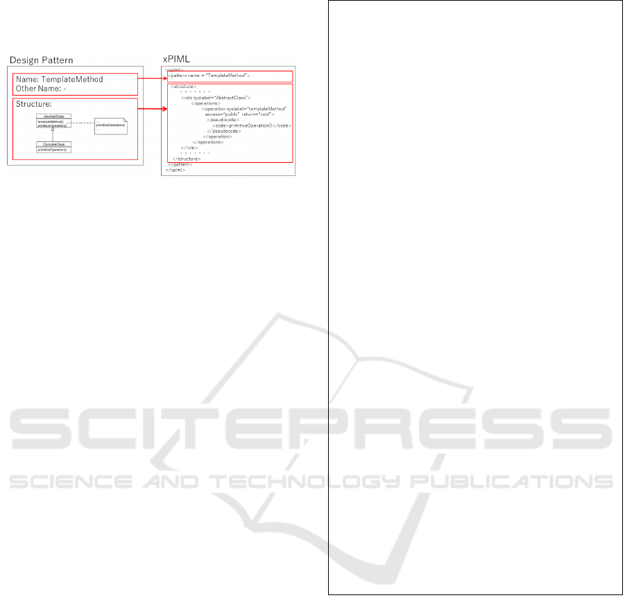
correspondence. The structure information is
described in the "structure" element as shown in
Figure 2.
Figure 2: Describing a Design Pattern in xPIML.
4.1 Description Structure
The structural information, including the behavior
described in the pseudocode, is described in three
parts: the relation definition group, the role definition
group, and the clonable group, based on the
information obtained from the UML class diagram.
First, relationships between classes, such as
inheritance, are described in the relation definition
group section "relations".
Next, the classes in the class diagram are called
roles and are listed in the "roles" section of the
role definition group. Each role is described in the
"role" element, and the operation of the role is
described in the "operation" element. The
behavior that may be described in operations is
described using Java-like pseudo-code.
Finally, some roles and operations that may exist
in multiple implementations are described in the
"clonables" section as replicable combinations.
For example, the method
primitiveOperation() of AbstractClass
of TemplateMethod can be implemented multiple
times with different names. In that case, multiple
primitiveOperation() of ConcreteClass
must be implemented as well. For this reason,
ptimiviveOperation() of AbstractClass
and primitiveOperation() of
ConcreteClass are defined to be "clonable"
as a set.
4.2 Description Example
Figure 3 shows an example of the TemplateMethod
design pattern description. For reasons of space, only
a part of this article has been excerpted.
Figure 3: TemplateMethod design pattern described in
xPIML.
5 MAPPING OF DESIGN
PATTERNS TO SOURCE CODE
We shall propose the entire structure of the mapping
between the design pattern and Java source code in
this section.
The use of frameworks and APIs is essential in
modern software development. To understand the
software structure, it is necessary to understand
architecture patterns and design patterns used in those
frameworks and APIs. These patterns are also used in
the design process of individual software. For this
<xpiml>
<pattern name = “TemplateMethod”>
<structure>
<relations>
<inheritance
origin="ConcreteClass"
target="AbstractClass"/>
</relations>
<clonables>
…
<clonable>
<celem type="op"
id="AbstractClass::
primitiveOperation"/>
<celem type="op"
id="ConcreteClass::
premitiveOperation"/>
</clonable>
</clonables>
<roles>
<role syslabel=“AbstractClass”>
<operations>
<operation
syslabel=“templateMethod
access=“public”
return=“void”>
<pseudocode>
<code>
primitiveOperation()
</code>
</pseudocode>
</operation>
…
</operations>
</role>
…
<roles>
</structure>
</pattern>
</xpiml>
CSEDU 2021 - 13th International Conference on Computer Supported Education
290

reason, we thought that it would be possible to deepen
the understanding of the learners if we could relate
these patterns, which are design knowledge, to source
code, which are artifacts of the implementation
process, and visualize the correspondence so that
design support and inspection can be performed.
In designing this system, we made the following
assumptions. Java will be used as the development
language in the lectures in our department. First, we
will cover the 23 design patterns of the GOF Book
(Gamma, 1995). It assumes the use of those in the
Java language library and popular frameworks such
as java.util, java.awt, and java.sql.
5.1 Visualization UI Concept
The image of the mapping between design patterns
and source code is shown in Figure 4. The
documented design pattern is displayed as a diagram,
and the correspondence between each element in the
design pattern and the corresponding code is
indicated using colors.
Figure 4: Example mapping between design patterns and
source code.
In Figure 4, the design pattern on the left side is
the TemplateMethod which has two roles. One role
AbstractClass is colored with blue and the
corresponding class AbstractDisplay in source code
is also colored with blue. The other role
ConcreteClass is colored with green and the
corresponding classes CharDisplay and StringClass
are also colored with green. When the
templateMethod in AbstractClass is selected and
highlighted with red, then the corresponding method
display() in AbstractDisplay is also highlighted with
red.
5.2 Mapping Algorithm
For documenting design patterns, we use xPIML, a
description language we developed previously
(Inoue, 2011). Since multiple design patterns may be
implemented within a single class, this description
language distinguishes the element that corresponds
to a class by calling it a "role". The element
corresponding to a method is called "operation".
To map the classes and interfaces in the
implemented source code to roles and the methods
contained in them to operations, it is necessary to
describe the mapping. A CSV file is used for this
description.
If there are multiple design patterns in an issue or
project, the mapping CSV files are created for all of
them. The following mapping algorithm is used for
the generation of each design pattern.
1. Do for each role in the design pattern.
1.1. If the role is implemented as multiple
classes, list them as one-to-many
correspondences.
1.2. If the role is implemented as a multi-level
class hierarchy, map it to the top-level
interface or class.
1.3. If there is a one-to-one correspondence
between the role and a class, describe it as
they are.
1.4. Do for each method in the role
1.4.1. If the operation is implemented as
multiple methods, list them as one-to-
many correspondences.
1.4.2. If multiple operations of a design
pattern are implemented together as a
single method, list them as a many-to-
one relationship.
1.4.3. If there is a one-to-one correspondence
between the operation and a method in
the source code, describe it as they are.
This kind of mapping makes it possible to
visualize the relationship between design patterns and
source code.
5.3 Folder Structure
The structure of the folder in which the data used in
this mapping system is stored is shown in Figure 5.
Here, the java folder contains the implemented
Java source code. Source code should be organized
by issue or project. The figure shows two folders, one
with the issue name "ex2020120101" and the
other with an example implementation of the design
pattern TemplateMethod. The source code may
include a nested hierarchy such as
"TemplateMethod/Sample". This folder also
includes the source code of the Java language library
such as java.lang and java.util in "java.base"
folder.
Generating Relationship between Design Pattern and Source Code
291

The xpiml folder contains the design pattern
description documents written in xPIML. It has the 23
design patterns of the GOF Book, which have been
described in previous studies.
The xpiml2java folder contains the CSV files
that describe the mapping between design patterns
and Java source code. The subfolder containing the
CSV files corresponds to the subfolder of the same
name of the source code of the issue or project placed
in the java folder.
data/
java/
ex2020120101/
Main.java
mypack/
Point.java
…
java.base/
…
(Java Language Library)
…
TemplateMethod/
Sample/
AbstractDisplay.java
CharDisplay.java
Main.java
StringDisplay.java
xpiml/
AbstractFactory/
Adapter/
...
(GOF 23 patterns)
...
TemplateMethod/
TemplateMethod.xml
Visitor/
xpiml2java/
ex2020120101/
TemplateMethod.csv
TemplateMethod/
TemplateMethod.csv
Figure 5: Folder structure used in the mapping system.
6 CSV FILE FOR MAPPING
The individual mapping between design patterns and
Java is described using a CSV file. The concrete
mapping rules are proposed in this section. The
validity of the rule is demonstrated using the example
described in Section 5.2.
6.1 Description Rules
The CSV file in which the mapping between design
patterns and Java source code is described is
composed as follows. The mappings between roles or
operations and classes or methods are generated using
the algorithm described in Section 5.2.
First, specify the location of the source code to
be targeted at the beginning. Use the relative
position from the data folder to specify the
position of the source code.
Next, list the mapping between the role
element specified by XPath and the class.
Classes should be written in a way that
includes packages.
Besides, list the mapping between the
operation element specified by XPath and the
method. Methods should be prefixed with the
class name, and the method name should be
written after "::".
java:TemplateMethod/Sample
/xpiml/structure/roles/role[@syslabel
="AbstractClass"],AbstractDisplay
/xpiml/structure/roles/role[@syslabel
="AbstractClass"]/operation[@syslabel
="templateMethod"],AbstractDisplay::d
isplay()
/xpiml/structure/roles/role[@syslabel
="AbstractClass"]/operation[@syslabel
="primitiveOperation"],AbstractDispla
y::open()
…(omitted)…
/xpiml/structure/roles/role[@syslabel
="ConcreteClass"],CharDisplay
/xpiml/structure/roles/role[@syslabel
="ConcreteClass"]/operation[@syslabel
="primitiveOperation"],CharDisplay::o
pen()
…(omitted)…
/xpiml/structure/roles/role[@syslabel
="ConcreteClass"],StringDisplay
/xpiml/structure/roles/role[@syslabel
="ConcreteClass"]/operation[@syslabel
="primitiveOperation"],StringDisplay:
:open()
Figure 6: CSV file for mapping TemplateMethod design
pattern and its implementation example.
6.2 Description Example
An example of a CSV file describing the
correspondence between the TemplateMethod pattern
and its implementation example is shown in Figure 6.
The source code for the implementation example
is located in "TemplateMethod/Sample" under
the java folder, the Java source code repository.
This location is specified in the first line
"java:TemplateMethod/Sample".
The AbstractDisplay class corresponds to
the AbstractClass role of the TemplateMethod
CSEDU 2021 - 13th International Conference on Computer Supported Education
292

pattern. In the second line, we map the xPath of
AbstractClass role to the AbstractDisplay
class. This mapping is generated from the algorithm
step 1.3 defined in Section 5.2.
In the line below, the templateMethod of
AbstractClass role in the TemplateMethod
pattern is mapped to the display() method of the
AbstractDisplay class. This mapping is
generated from the algorithm step 1.4.3.
Further down the line, the open() method is
mapped to the primitiveMethod operation.
Several other methods correspond to
primitiveMethod, such as close(), but they
have been omitted for the sake of space. This
mapping is generated from the algorithm step 1.4.1.
The two classes corresponding to
ConcreteClass are CharDisplay class and
StringDisplay class. This mapping is generated
from the algorithm step 1.1.
Under the row where these classes are mapped to
the ConcreteClass role, the
primitiveMethod operation and the open()
method are mapped, respectively. This mapping is
generated from the algorithm step 1.4.3.
7 CONCLUSIONS
We propose a mechanism to generate a mapping
between the design pattern and source code in this
paper. The mechanism will be integrated into VRale-
SCM to develop a design pattern source code
correspondence display system as one of the
functions to understand and check the relationship
between the artifacts of the design process and the
ones of the implementation process. We used the
previously designed description language xPIML to
describe the design patterns. The designed new
mapping rules are described in CSV files to map them
to the source code.
Currently, based on this design, we are working
on mapping the design pattern description to the
source code. In the future, we will design and develop
a function to display them in the VR space and allow
learners to view them.
ACKNOWLEDGEMENTS
This research is supported by JSPS Kakenhi Grant
No. 20K03232. We also appreciate the students
working on the development of VRale-SCM and
other tools.
REFERENCES
Albin-Amiot, H., Gueheneuc, Y., 2000. Metamodeling
Design Patterns: application to pattern detection and
code synthesis, In Proc. of Workshop on Adaptative
Object-Models and Metamodeling Techniques at
ECOOP'01.
Budinsky, F., Finnie, M., Vlissides, J., Yu, P., 1996.
Automatic code generation from design patterns, IBM
Systems Journal, 35(2).
Caiza, J.C., Del Alamo, J.M., 2013. Programming
assignments automatic grading: Review of tools and
implementations, In Proc. 7th Technology, Education
and Development (INTEND 2013), pp. 5691-5700.
Dwivedi, A., Rath, S., Satapathy, S., 2019. Neural Network
Based Patterns Detection in Object-Oriented Program,
2019 9th Annual Information Technology,
Electromechanical Engineering and Microelectronics
Conference (IEMECON), Jaipur, India, pp. 183-188
Gamma, E., Helm, R., Johnson, R., Vlissides, J., 1995.
Design Patterns: Elements of Reusable Object-
Oriented Software, Addison Wesley Professional
Inoue, H., 2011. xPIML: Structured Document Framework
for Design Patterns using XML, A Graduation Thesis
in Department of Information Science, Faculty of
Science and Engineering, Saga University.
ISO/IEC/IEEE 12207:2017 Systems and software
engineering — Software life cycle processes
Kishikawa, M., Kakeshita. T., 2020. A Visualization Tool
for Relationship between Source Code and Parse Tree,
9th International Conference on Learning
Technologies and Learning Environments (LTLE2020),
pp. 203-208
Kobayashi, T., Kamo, M., Sanui, T., Saeki, M., 2000.
Object-Oriented Modeling of Software Patterns, In
Proc. of ISPSE2000.
Ohtsuki, M., Segawa, J., Yoshida, N., Makinouchi, A.,
1998. Visual Aids for Cataloging and Code Generation
for SGML-based Documents of Design Patterns,
Proceedings of Third World Conference on Integrated
Design and Process Technology 1998 (IDPT’98), pp.
829-834
Ohtsuki, M., Yoshida, N., Makinouchi, A., 1999. A Source
Code Generation Support System Using Design Pattern
Documents Based on SGML, Proceedings of
APSEC99, pp. 292-299
Shizuki, B., Toyoda, M., Shibayama, E., Takahashi, S.,
2000. Smart Browing among Multiple Aspects of
DataFlow Visual Program Execution, Using Visual
Patterns and Multi-Focus Fisheye Views, Journal of
Visual Languages and Computing, 11(5).
Generating Relationship between Design Pattern and Source Code
293
