
Energy Efficiency of Low Voltage Direct Current Supplies
Including PV Sources
Anis Ammous
1
, Ammar Assaidi
1
, Abdulrahman Alahdal
1
and Kaiçar Ammous
2
1
Department of Electrical Engineering, College of Engineering and Islamic Architecture, Umm Al-Qura University, K.S.A.
2
Department of Electrical Engineering, National School of Engineers of Sfax, University of Sfax, Tunisia
Keywords: Renewable Energy, Power Electronics, LVDC, Energy Efficiency.
Abstract: The low Voltage Direct Current (LVDC) system concept has been growing in the recent times due to its
characteristics and advantages like renewable energy source compatibility, more straightforward integration
with storage utilities through power electronic converters and distributed loads. This paper presents the
energy efficiency performances of a proposed LVDC supply concept and others classical PV chains
architectures. A PV source was considered in the studied nanogrids. The notion of Relative Saved Energy
(RSE) was introduced to compare the studied PV systems energy performances. The obtained results
revealed that the employment of the LVDC chain supply concept is very interesting and the use of DC loads
as an alternative to AC loads, when a PV power is generated locally, is more efficient. The installed PV
power source in the building should be well sized regarding to the consumed power in order to register a
high system RSE.
1 INTRODUCTION
The photovoltaic electricity was primarily
established for standalone applications deprived of
any connection to a power grid. Such was the case of
satellites or isolated habitations. Currently, PV's are
found in many power applications like personal
calculators, watches and other objects of daily use,
they can supply many individual DC loads without
difficulty. The main objective of this paper is to
investigate the energy efficiency performance of a
proposed Low-Voltage Direct Current (LVDC) PV
system regarding to a classical LVDC architecture
and classical PV systems using AC loads. All the
studied PV chains are on-grid ones and are supposed
supplying offices.
In general, electric energy consumption in office
applications and housing is achieved by using the
alternative current plugs even for Grid Tie PV panel
systems. In this case the use of AC's can increase
system losses especially when DC current is used at
the load levels.
LVDC systems have been gaining more interest
during the past few years both in academia and
industry. LVDC systems offer many advantages
covering higher energy efficiency and easier
integration of modern energy resources in
comparison to conventional AC systems.
Direct use of DC power would reduce many
power conversion losses by exploiting self-
consumption of the energy produced on site and
decreasing imports of electricity from the grid. DC
loads used in households and office buildings, also
operate on DC, heating/cooling systems and larger
equipment used in industry such as variable
frequency drives have also adopted DC motors.
Direct current power systems are essentially more
efficient than their AC counterparts; since in DC
systems do not suffer from skin effect or reactive
power (Leonardo et al., 2016; IEC, 2016; D. Kumar
et al., 2017; Gyuyoung Yoon et al., 2019).
A literature research has exposed the study of the
first system analysis explored the use of very low
voltage (<120 V) in small-size systems, particularly
residential dwellings (J Pellis, 1997).
Subsequently, Lasseter R.H proposed the
concept of the DC Microgrid as a low voltage
distribution network. This concept was projected as
the future low voltage distribution systems which
were facing revolutionary variations at the time due
to emanation of distributed generation and market
liberalization. The basic idea behind this concept is
to combine micro sources and loads into one entity
188
Ammous, A., Assaidi, A., Alahdal, A. and Ammous, K.
Energy Efficiency of Low Voltage Direct Current Supplies Including PV Sources.
DOI: 10.5220/0010471001880195
In Proceedings of the 10th International Conference on Smart Cities and Green ICT Systems (SMARTGREENS 2021), pages 188-195
ISBN: 978-989-758-512-8
Copyright
c
2021 by SCITEPRESS – Science and Technology Publications, Lda. All rights reserved

which could be interpreted as a single dispatch-able
load that could respond in short time to meet the
transmission system needs (R. H. Lasseter, 2002).
For many years, The LVDC system has been
developed for specific applications like aerospace,
automotive and marine (A. Ghareeb et al., 2013),
(Ahmed T et al., 2015), (Jifei Du et al., 2019).
Literature review reveals that over the last decades,
LVDC systems are growing rapidly for industrial
applications, essentially in the telecommunication
industry, ships and buildings. Adopting Direct
Current in data centers improve efficiency, decrease
capital cost, increase reliability and boost power
quality (AlLee et al., 2012). In data centers, LVDC
architectures have been widely studied. Various
leader projects have been installed in Europe, the
United States, Oceania and Asia. From these
projects it was registered that the profit of DC in
data-centers are about 10% to 30% reduction in
energy consumption, about 15% lower capital costs,
simpler design, potential increase in reliability, less
physical area requirements, a smaller carbon
footprint and less cooling demand (Tomm Aldridge,
2009), (Brian Fortenbery, 2011).
The most significant challenge that DC
distribution systems face today is the lack of
standardization inducing varied architectures and
operations of DC distribution systems (Kiran and
Hassan, 2020), (Paul, Robert and Sean, 2010).
The work presented in (V. Vossos et al., 2014)
was accomplished in many various locations through
the country, with different types of system
topologies. Further, distribution topologies were
carried out for both two cases with and without
energy storage.
Studies conducted in (V. Vossos et al., 2014),
(Paul, Robert and Sean, 2010) aim to accomplish 25-
30% of energy savings. The environment
conditioning loads are very significant part in
Buildings and should be explored in further studies.
The authors in (Patterson, B. T, 2012) reported
that the majority of electricity used in on office
building passes through power converters enclosing
further conversions. Average conversion efficiency
is closed 68%. When using high quality electronics,
only a 10% loss from each stage of conversion is
considered as generous number.
The DC power is directly produced from
residential solar panels and inverter is commonly
added to supply AC loads.
Despite that the multi-stage conversion is basic
to extract power from the solar panel into the server;
losses resulting from these conversions are expected
to be between 10% and 25%.
Through review of the available literature
(Leonardo et al., 2016), (Gyuyoung Yoon et al.,
2019), (Kiran and Hassan, 2020), (Yu Zhang et al.,
2020), local DC grids are a promising option for
buildings to link natural DC power sources such as
photovoltaic power systems with DC loads like
lighting applications and data centers (Tomm
Aldridge, 2009), (Kiran and Hassan, 2020).
(A. AMMOUS and H. Morel, 2014) reported that
DC microgrids are alternatives promising to
conventional AC distribution networks especially for
the integration of renewable energies. They allow,
for example, to reduce consumption energy of 25%
when supplying buildings directly from sectors and
by photovoltaic panels.
The majority works on DC distribution grids
assume that converters are installed at each
household, which connect the local DC or AC
nanogrids (Patwa and Saxena, 2020) ,(X. Yue et
al.,2018). In case of distributed energy resources,
nanogrids in buildings could be functioned
separately from the main grid in islanding mode (X.
Yue et al.,2018) and typical low voltage subsystems
like 48V, 24V, or 12 V can be applied (Rodriguez-
Diaz et al., 2016). They could, for example, be used
for low power LED lighting or for connecting loads
by USB Type-C connector and USB Power
Delivery.
In the first part of the paper, we focused our
study on the state of the art related to the use of the
LVDC supply concept and the proposition of an on-
grid LVDC PV chain. The disadvantage of the use
of classical on-Grid PV systems and of using AC
plugs to supply electric DC loads are shown. The
used average model of power converters is then
presented in the second part. This model allows the
evaluation of the different converters efficiencies in
the studied PV chains. The last part of the paper
treats the energy efficiency performances of the
proposed LVDC system compared to others classical
ones. For this purpose, offices loads are considered
and Jeddah location (in KSA) was chosen in our
study.
2 THE PROPOSED LVDC PV
SYSTEM
Electronic appliances, such as computers, gaming
consoles, printers, economic LED lights, televisions
and so on need DC supplies. Additional AC to DC
converters are needed in such equipment.
Energy Efficiency of Low Voltage Direct Current Supplies Including PV Sources
189
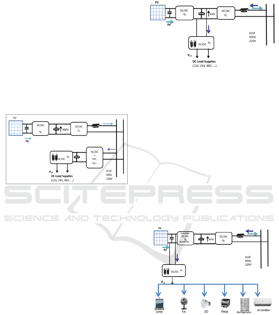
Figure1 shows one of classical chain used to
connect PV panels to the low voltage grid with a
transformerless solution. The DC/DC converter,
Converter #1, allows the extraction of the maximum
power from the PV panels when climatic conditions
changes. The Maximum Power Point Tracking
(MPPT) algorithm is used to act on this DC/DC
converter control.
The DC/AC converter, Converter #2, transfers
the PV generated power to the grid and ensures the
regulation of the DC voltage value (400 V) of the
inverter input. This DC value is mainly used value
for single phase PV systems allowing to obtain
easily the standard 230 V AC. The injected current
to the grid has a quasi-sinusoidal waveform.
Figure 1: Classical configuration (syst1) of the On-Grid
PV system and DC load powered from AC sockets.
A main used LVDC photovoltaic architecture is
shown in figure 2. This system involve direct current
chain form PV to load. The regulated DC bus (400
V) was used for this purpose and a DC/DC converter
(η
3
) adapts LVDC loads supplies to this DC bus.
The efficiency of each PV conversion chain
depends on different considerations like the type of
used power semiconductor devices and the
magnitude of the transferred power.
Following we will present the proposed new PV
architecture for DC loads supplies and the developed
average model of power converters. The proposed
LVDC PV chain uses the DC bus available directly
after the PV panels. This bus is not regulated but it's
value varies in a given range depending on PV
panels associations (parallel/series) and open circuit
voltage across each panel.
The regulation of the DC voltages supplying
loads are regulated by DC/DC converters (in general
Buck ones). The proposed architecture is the one
shown in figure 3. The DC/DC converter connecting
the PV panels to the inverter become a reversible
DC/DC converter (Buck-Boost).
Figure 2: Possible LVDC classical architecture (syst2).
The last converter allows the transfer of power from
PV panels to the inverter when the generated power
is higher than the consumed power. This reversible
converter works as a Buck converter in the case
when the consumed power is higher than the PV
generated one. Both, system2 and system3 use the
same number of converters, the advantage of the
proposed architecture (syst3) is that the path of the
power from the PV source to the Load is shorter
during a day. during a luck of PV power, sure the
path of the power become higher from the grid to the
load. In order to judge the efficiency of the different
configurations a simulations was performed during a
typical days (24 hours/day) in each season and then
the saved energy will be evaluated during a
complete year (365 days). The effect, of the
generated energy magnitude by the load consumed
energy magnitude, on the systems performances was
studied too.
Figure 3: Proposed LVDC architecture (syst3).
3 POWER CONVERTERS
MODELS
Modeling is required to analize the dynamic
behavior of a power converter in several
applications. Since both accuracy and simulation
SMARTGREENS 2021 - 10th International Conference on Smart Cities and Green ICT Systems
190
rapidity are essential particularly for long time
simulations and for complicated circuits, the
averaging method is the widely used technique for
complex power electronics systems. Based on the
classical averaged model, the converter is considered
to be a linear system using ideal switches, however
the non-linear averaged model is established on
semiconductor device models including static and
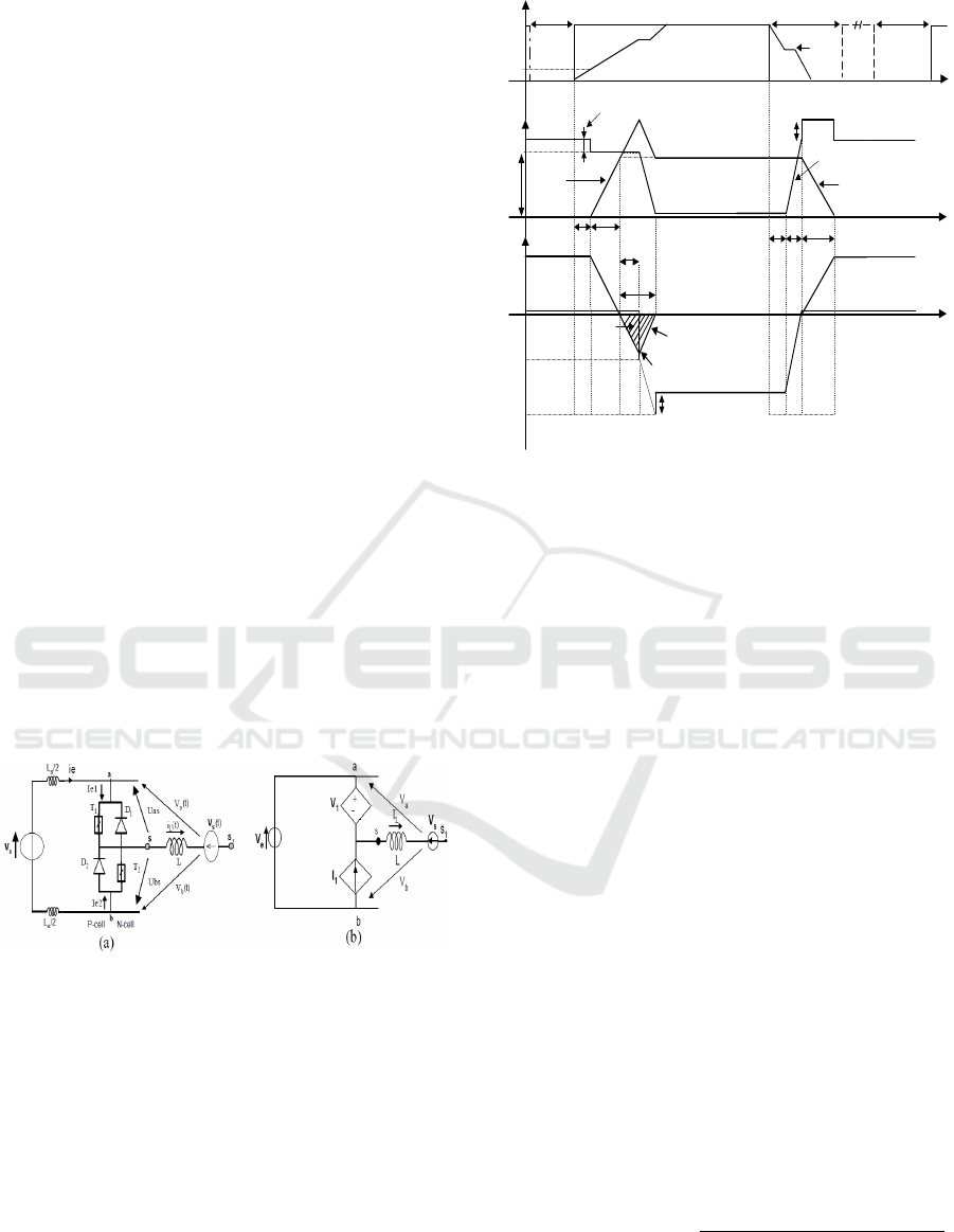
dynamic characteristics of the switches. Figure 4(a)
shows the considered inverter leg with two active
switches (IGBTs or MOSFETs) directly controlled
by external control signals and two passive switches
(DIODEs). In Figure 4(b), the adopted leg circuit
based on the used averaged model is presented. In
this developed model, the leg switches are replaced
by a controlled voltage source V
1
in series with a
controlled current source I
1
given by (A. AMMOUS
et al., 2003
).
as
1
VU=
and
1e2
Ii=
(1)
With
as
U
and
e2
i
are the time averaged values of
the instantaneous terminal waveforms of U
as
(t) and
i
e2
(t) respectively over one cycle Ts (switching
period of the controlled switches).
Figure 5 shows the adopted switching waveforms
of the active switch (U
as
(t), i
e1
(t)) and the passive
switch (U
bs
(t), i
e2
(t)) during the switching period T
s
.
The driving signals e
g1
and e
g2
are the control signals
of T
1
and T
2
respectively.
Figure 4: (a) The PWM-switch, (b) The corresponding
averaged model.
The power losses of semiconductors (P
switch
and
P
diode
) are estimated using this analytical
representation of the switching characteristics which
including both conduction and switching losses, and
considering the various conduction and switching
times.
Different static and dynamic power devices
parameters can be deduced from their data sheets or
by experiments.
V
e
+V
d
V
t
V
st
I
L
i
e1
(t)
U
as
(t)
i
e2
(t)
U
bs
(t)
t
don
t
r
t
rr
t
IRM
t
doff
e
g1
(t)
t
t
t
T
on
T
s
V
str
V
q
dI
F
/dt
dI
R
/dt
e
g2
(t)
Q
r
(dI
F
/dt)
off
I
RM
0
-(V
e
-V
t
)
dV
DS
/dt
L
st
.(dI
F
/dt)
V
X
V
RM
t
0
t
4
t
1
t
3
t
2
V
d
t
fi
t
rv
t
5
t
6
t
7
t
8
V
th
V
gs
(t)
V
gp
Figure 5: Adopted switching characteristics for the switch
and the diode components in the PWM-switch cell.
The developed average model allows computing
all the dissipated power in the semiconductor
devices and then deducing the different converters
efficiencies (A. AMMOUS et al., 2003). Time
domain simulations will be more rapid for the whole
PV chain system.
The efficiencies of the different converters used
in the different chains were evaluated by mean of
refined simulations. The evolutions of these
efficiencies as a function of the transferred power
ɳ(P) are shown in figure 6. The used, controlled,
devices in the converters are the N-channel SiC
power Mosfet's SCT3080KL. Internal anti-parallel
diode of the Mosfet is used for reverse current in the
switch.
We defined the saved energy, W
i
(i=1,2,3), by a
PV chain, the excess of energy injected in to the grid
after satisfying the load need. It is the energy
balance per month. We note that the chosen
maximum power generated by the PV panel is
1500W for a 25˚C Temperature and 1000W/m
2
Irradiance conditions.
4 STUDY OF LVDC SOLUTIONS
EFFICIENCIES
Jeddah-KSA location (21° 32′ 34″ N, 39° 10′ 22″ E)
was chosen to perform energy efficiency
performances of the different studied PV chains.
Energy Efficiency of Low Voltage Direct Current Supplies Including PV Sources
191
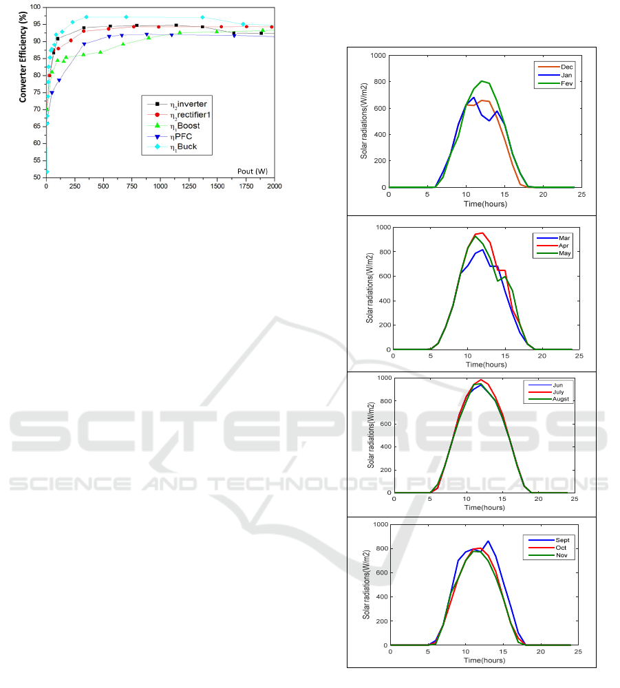
Figure 6: Different converters efficiency.
Jeddah features an arid climate under Koppen's
climate classification, with a tropical temperature
range.
The following graphs in figure 7 shows the solar
radiation during a typical day in each month for
Jeddah city, which was monitored from the station
of University King Abdul-Aziz. In the figure graphs
typical days divided by seasons. A higher value of
solar radiation in July and reaches nearly to more
than 984 W/m
. The generated power by the panels
during a typical day of January in Jeddah is shown
in figure 8. The PV panels generated energy in this
case is 6600 Wh/day.
The annual generated energy by the used PV
panels W
PV
is equal to 3.006 MWh.
First, a load profile of an office was chosen in
order to make comparison of the saved energy by the
three studied PV chains. The profile of the load is
shown in the following figure 9 and the daily
consumed energy by one office is 2919 Wh.
The annual consumed energy by one office is
supposed to be about W
Load
= 1.068 MWh.
The considered office load is composed by,
Desktop computer (180 W), Laptop (50 W), Laser
printer (600W peak, 150 W average during a cycle),
two Led lamps (20W), small TV (20 W) and a fan
(25W). Since the DC/DC converter(η
3
) is common
for the three studied converters and located just
before the load, it's effect was not taken into account
in the study.
Matlab simulator tool was used to study the
different power PV systems efficiencies. The saved
energy by the three models during each month of the
year in Jeddah city is shown in figure 10. It is
evident that the saved energy decreases with the
increase of consumed power. From figure 10, it's
clear that the proposed new LVDC architecture
(syst3) is the best one and register a higher saved
energy (W
3
=1.467 MWh/year when only one office
load is considered) compared to the other chains
(W
2
=1.357 MWh/year and W
1
=1.319 MWh/year
when only one office load is considered too).
Figure 7: Solar radiations of typical days for each month
and seasons.
From figure 10, it's clear that the proposed new
LVDC architecture (syst3) is the best one and
register a higher saved energy (W
3
=1.467 MWh/year
when only one office load is considered) compared
to the other chains (W
2
=1.357 MWh/year and
W
1
=1.319 MWh/year when only one office load is
considered too).
SMARTGREENS 2021 - 10th International Conference on Smart Cities and Green ICT Systems
192
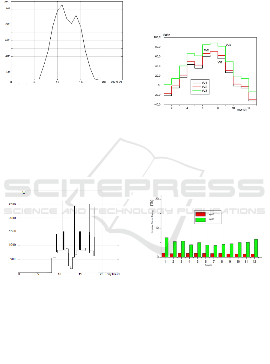
Figure 8: Generated power, by the used panels, during a
typical day of January in Jeddah.
This is due to the localization of the load connection,
in the LVDC chain, close to the PV panels which is
the main introduced modification in the proposed
LVDC system regarding to classical LVDC ones.
We note that when the saved energy W
i
is negative
this mean that the consumed energy is higher than
generated one and so, this energy is transferred
from the grid to the PV system.
This generated energy was calculated based on
Irradiance, ambient Temperature and wind speed in
Jeddah during each typical day/month in the year.
Figure 9: The assumed daily office load consumption (by
1 office).
We will describe the assess of the efficiency of the
proposed LVDC PV chain solution (syst3) compared
to the LVDC classic one (syst1) and the classical
On-grid PV chain (syst2) using AC loads. We varied
the consumed Energy by the load and we registered
the saved energy by each PV system. It was
remarked a very interesting propriety of the PV
LVDC systems related to the increase of their
efficiency compared to classical PV chain. In fact,
we define the Relative Saved Energy (RSE
j
%) of
the PV LVDC chain (syst j) to the classical PV chain
(syst1), the ratio of the excess of saved energy of the
given LVDC chain (W
2
or W
3
) regarding to the
classical PV system (W
1
) by the value of the annual
generated PV energy W
PV
.
Figure 10: Annual saved energy by the three PV chains
models (syst1), (syst2), proposed LVDC (syst3)) for each
month of the year in Jeddah city and for one office.
The defined PV system RSE
j
regarding to the
classical PV chain is given by the following
equation.
RSE
j
(%) =(W
j
-W
1
)/W
PV
x 100% with j=2,3 (2)
RSE gives an evaluation of the relative saved energy
if we use system2 or system3 instead of system1.
Figure 11: Relative Saved Energy for the two systems, 2
and 3 in each month (number of offices =1).
If the defined efficiency is negative this mean that
classical On-Grid PV chain (syst1) using AC sockets
for load supplies is better (in term of energy saving)
than the PV LVDC supplies concept.
Figure11 shows the relative saved energy for the
two systems 2 and 3 in January (office=1). The
figure 11 illustrates that the relative saved energy for
the systems3 is more important than the system 2.
The waveforms giving the evolution of the
LVDC chains RSE as function of load energy by PV
energy rate (
) is shown in figure 12. Two main
Energy Efficiency of Low Voltage Direct Current Supplies Including PV Sources
193
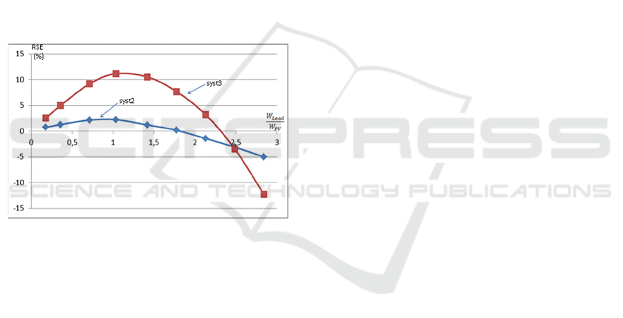
observations can be highlighted when interpreting
these waveforms:
First, it is clear that the RSE of the proposed
LVDC chain (syst3) is higher than the classical
LVDC one (syst2) till a high load consumed energy
(2.5 times the PV generated energy in our case).
Second, an optimum of these waveforms are
registered when the consumed energy is around the
generated energy by the PV panels. The maximum
yearly RSE of the new LVDC architecture (syst3) is
about 12% while the one registered by the classical
LVDC chain (syst2) is about 2.3%.
From figure 12, we can remark that when the
load power consumption increases, the RES
becomes negative, this mean that the classical PV
chain, using AC supply to feed loads, is better
solution than the LVDC one in this case. We can
remark also, that for a high load consumption, the
LVDC chain (syst2) becomes more interesting than
the proposed LVDC chain (syst3).
Figure 12: Yearly Relative Saved Energy of classical
LVDC system2 and proposed LVDC system3.
In addition, the use of system3 allows the increase of
the load energy consumption range (more than two
times the generated PV energy) where the LVDC
supply concept efficiency is higher than other
systems.
All the obtained results show that the use of the
LVDC chain supply concept is very interesting and
the use of DC loads instead of AC loads when a PV
power is generated locally increases the PV system
efficiency.
The installed PV power in the building should be
well sized regarding to the consumed power in order
to register a high system RSE. In this case an LVDC
system RSE can be higher than 10% compared to the
classical AC supply in PV systems.
5 CONCLUSION
In this paper we proposed a new architecture of a
Low Voltage Direct Current (LVDC) supply
concept. The proposed on grid PV chain system,
involving DC loads, can replace the classical on-
Grid PV systems using AC plugs to supply electric
AC loads. To evaluate the efficiency of some
different PV chains, non-ideal averaged models of
the different converters, have been used. These
models are accurate and suitable to complex systems
study. The Energy efficiency of the different PV
chains were estimated by mean of simulations. The
evaluation of the efficiency of the proposed new
LVDC architecture compared to the classical one
was performed in the case of building offices in
Jeddah. The superiority of the proposed LVDC PV
chain was shown, it depends on the consumed load
energy to generated PV Energy ratio.
ACKNOWLEDGEMENTS
This paper contains the results and funding of a
research projects funded by King Abdulaziz City for
Science and Technology (KACST) Grant no. 14-
ENE2677-10.
REFERENCES
A. AMMOUS and H. Morel, “LVDC: An Efficient
Energy Solution for on-Grid Photovoltaic
Applications” Smart Grid and Renewable Energy,
2014, Vol. 5, No. 4, pp. 63-76.
A. AMMOUS et al « Developing a PWM-switch model
including Semiconductor Device Non-linéarities »
IEEE Transactions on Power Electronics, Vol.18,
No.5 ,September 2003.
A. Ghareeb, A. Mohamed, and O. Mohammed, “DC
microgrids and distribution systems: An overview,” in
Power and Energy Society General Meeting (PES),
2013 IEEE, Jul 2013, pp. 1–5.
Ahmed T. Elsayeda, Ahmed A. Mohamedb, Osama A.
Mohammeda,” DC microgrids and distribution
systems: An overview”, Electric Power Systems
Research 119 (2015) 407–417.
AlLee, G., and Tschudi, W., “Edison redux: 380 vdc
brings reliability and efficiency to sustainable data
centers,” IEEE Power Energy Mag., Vol. 10, No. 6,
pp. 50–59, November2012.
Brian Fortenbery. “DC Power Standards”, Technical Report
March, Electric Power Research Institute, 2011.
D. Kumar et al,” DC Microgrid Technology: System
Architectures, AC Grid Interfaces, Grounding
SMARTGREENS 2021 - 10th International Conference on Smart Cities and Green ICT Systems
194

Schemes, Power Quality, Communication Networks,
Applications, and Standardizations Aspects,” IEEE
Access.,vol, 5,pp. 12230-12256, 2017.
Gyuyoung Yoon, Kyoko Sugiyama, Saya Yoshioka and
Shinji Sakai,” Energy Efficiency and Cost
Performance of Direct-Current Power Supply Systems
in Residential Buildings by 2030s and 2050s”, E3S
Web of Conferences 111 CLIMA 2019.
International Electrotechnical Commission (IEC) Report
on LVDC Electricity for the 21st Century, 2017.
J Pellis. The DC low-voltage house. Graduation project,
Eindhoven University of Technology,1997.
Jifei Du, Trillion Q. Zheng, Yian Yan , Hongyan Zhao,
Yangbin Zeng and Hong Li,” Insulation Monitoring
Method for DC Systems with Ground Capacitance in
Electric Vehicles », Appl. Sci. 2019, 9, 2607, pp.1-15.
Kiran Siraj, Hassan Abbas Khan,''DC distribution for
residential power networks—A framework to analyze
the impact of voltage levels on energy efficiency'',
Energy Reports, Volume 6, 2020, Pages 944-951.
Leonardo Trigueiro dos Santos, Manuela Sechilariu and
Fabrice Locment,” Optimized Load Shedding
Approach for Grid-Connected DC Microgrid Systems
under Realistic Constraints,” Buildings, pp1-15, 2016.
Patterson, B. T,” Dc, come home”. IEEE power & energy
magazine (2012, November/December), pp.60-69.
Patwa, K.., & Saxena, D. R. ''Review on Power System
Performance in High/Low Voltage Distribution System''
smart moves journal ijosthe, Vol.7, No.6, (2020).
Paul Savage, Robert R. Nordhaus, and Sean P. Jamieson.
DCMicrogrids: “Benefits and Barriers”.Technical
report, Yale School of Forestry and Environmental
Studies, 2010.
R. H. Lasseter, “Microgrids,” in Power Engineering
Society Winter Meeting, 2002. IEEE, 2002, vol. 1, pp.
305–308.
Rodriguez-Diaz, E., Chen, F., Vasquez, J. C., Guerrero, J.
M., Burgos, R., and Boroyevich, D., “Voltage-Level
Selection of Future Two-Level LVdc Distribution
Grids: A Compromise Between Grid Compatibiliy,
Safety, and Efficiency,” IEEE Electrif. Mag., Vol. 4,
No. 2, pp. 20–28, June 2016.
Tomm Aldridge.” Direct 400Vdc for Energy Efficient
Data Centers Direct 400Vdc Facility Vision”.
Technical Report April, Intel Corporate Technology
Group, 2009.
V. Vossos et al.” Energy savings from direct-DC in U.S.
residential buildings”, Energy and Buildings 68
(2014), pp.223–23.1
X. Yue, D. Boroyevich, F. C. Lee, F. Chen, R. Burgos
and F. Zhuo, "Beat frequency oscillation analysis for
power electronic converters in dc nanogrid based on
crossed frequency output Impedance matrix model," in
IEEE Transactions on Power Electronics, vol. 33, no.
4, pp. 3052–3064, Apr. 2018..
Yu Zhang, Shuhao Wei, Jin Wang and Lieping Zhang,”
Bus Voltage Stabilization Control of Photovoltaic DC
MicrogridBased on Fuzzy-PI Dual-Mode Controller”,
Journal of Electrical and Computer Engineering,
Volume 2020, Article ID 2683052, 10 pages.
Energy Efficiency of Low Voltage Direct Current Supplies Including PV Sources
195
