
Generation of Road Reference Heading using GPS Trajectories for
Accurate Lane Departure Detection
Shahnewaz Chowdhury, Md. Touhid Hossain and M. I. Hayee
Department of Electrical Engineering, University of Minnesota Duluth, Duluth, MN 55812, U.S.A.
Keywords: Lane Departure Warning System, Road Reference Heading, GPS Trajectory.
Abstract: Lane departure warning system (LDWS) has significant potential to reduce crashes on roads. Most existing
commercial LDWSs use image processing techniques with or without Global Positioning System (GPS)
technology and/or high-resolution digital maps to detect unintentional lane departures. However, the
performance of such systems is compromised in unfavourable weather or road conditions e.g., fog, snow, or
irregular road markings. Previously, the authors proposed and developed an LDWS using a standard GPS
receiver without any high-resolution digital maps. The previously developed LDWS relies on a road reference
heading (RRH) of a given road extracted from an open-source low-resolution mapping database to detect an
unintentional lane departure. This method can detect true lane departures accurately but occasionally gives
false alarms i.e., it issues lane departure warnings even if a vehicle is within its lane. The false alarms occur
due to the inaccuracy of RRH originated from inherent lateral error in open-source low-resolution maps. To
overcome this problem, now authors propose a novel algorithm to generate an accurate RRH for a given road
using a vehicle’s past trajectories on that road. The newly proposed algorithm to generate an accurate RRH
for any given road has been integrated with the previously developed LDWS and extensively evaluated in the
field to detect unintentional lane departures. The field test results show that the newly developed RRH
generation algorithm significantly improves the performance of the previously developed LDWS by
accurately detecting all true lane departures while practically reducing the frequency of false alarms to zero.
1 INTRODUCTION
Lane departure warning system (LDWS) has
significant potential to reduce accidents. According to
the American Association of State Highway and
Transportation Officials (AASHTO), almost 60% of
fatal accidents are caused by an unintentional lane
drifting of a vehicle on major roads (AASHTO:
Driving down lane-departure crashes: A national
priority, 2008). A recent study which compared
crashes with and without an LDWS found that an in-
vehicle LDWS was helpful in reducing crashes of all
severities by 18%, with injuries by 24%, and with
fatalities by 86% (J Cicchino, 2018). Systems which
predict the driver’s attentive state and intent of lane
change (D. D. Salvucci, 2004, N. Kuge et al. 1998, J.
McCall et al. 2004) and provide map-based route
guidance and/or warning about unintentional lane
departure (F. Heimes et al. 2002, W. Kwon et al.
2002), are also useful to reduce major road crashes.
Most available LDWSs rely on image processing
technology using a camera or an optical scanning
device to estimate a vehicle’s lateral shift within a
lane to detect an unintentional lane departure
(Xiangjing An et al. 2006, Pei-Yung Hsiao et al.
2006, B. Yu et al. 2008, Y. C. Leng et al. 2010, P.
Lindner et al. 2009). Although advanced image
processing techniques work well in diminished
lighting scenarios (McCall et al. 2006, Daimler,
2018) the performance of image processing based
LDWSs deteriorates in unfavourable weather and
road conditions e.g., fog and snow-covered or worn-
out road marking signs. To overcome these problems
and improve performance, Global Positioning System
(GPS) technology is integrated within vision based
LDWS. However, such systems use differential GPS
technology and/or inertial navigation sensors as well
as high-resolution digital maps to estimate a vehicle’s
lateral shift in its lane making such systems more
complex and expensive to implement (
Clanton, 2009).
Previously, the authors proposed a novel method
to accurately detect an unintentional lane departure
using a standard GPS receiver and commonly
available open-source low-resolution digital maps
584
Chowdhury, S., Hossain, M. and Hayee, M.
Generation of Road Reference Heading using GPS Trajectories for Accurate Lane Departure Detection.
DOI: 10.5220/0010465405840593
In Proceedings of the 7th International Conference on Vehicle Technology and Intelligent Transport Systems (VEHITS 2021), pages 584-593
ISBN: 978-989-758-513-5
Copyright
c
2021 by SCITEPRESS – Science and Technology Publications, Lda. All rights reserved
(Faizan et al. 2019). The previously proposed method
estimates vehicle’s lateral shift by comparing
vehicle’s heading acquired by standard GPS receiver
to a road reference heading (RRH) extracted from an
open-source digital map. Although this system works
well to successfully detect unintentional lane
departure, occasionally, it generates false alarms i.e.,
it wrongfully issues lane departure warnings even if
the vehicle is within its lane (Faizan et al. 2019). The
false alarms occur due to inherent error in open-
source digital maps which resulted in an error in the
corresponding RRH of the given road extracted from
such maps. The authors now propose another method
to generate an accurate RRH for any given road using
a vehicle’s past GPS trajectories on that road without
relying on open-source digital maps.
Previously, many techniques have been proposed
to process GPS trajectories to generate a routable road
network or create a complete digital road map using
graph and structured learning theory and/or statistical
analysis (Cao et al. 2009, Guo et al. 2007, Chen et al.
2008, Guo et al. 2010, Shi et al. 2009, Huang et al.
2018). In this paper, a novel algorithm is proposed to
generate an accurate RRH from a vehicle’s past GPS
trajectories to improve the performance of the
previously proposed lane departure detection method
(16). The test results show that the newly proposed
algorithm significantly improves the performance of
the previously proposed lane departure detection
method by accurately detecting all true lane
departures while practically reducing the frequency
of false alarms to zero.
The rest of the paper is organized as follows.
Section 2 describes the system architecture of the
proposed lane departure system using RRH generated
from a vehicle’s past trajectories. The details of the
newly proposed RRH generation algorithm are
provided in Section 3, and the field test results are
discussed in Section 4. The conclusions are given in
Section 5.
2 SYSTEM ARCHITECTURE
The newly proposed algorithm generates RRH for
any given road using a vehicle’s one or more past
trajectories on that road acquired by a standard GPS
receiver. Once an RRH for a given road is generated,
it can be used to detect any future unintentional lane
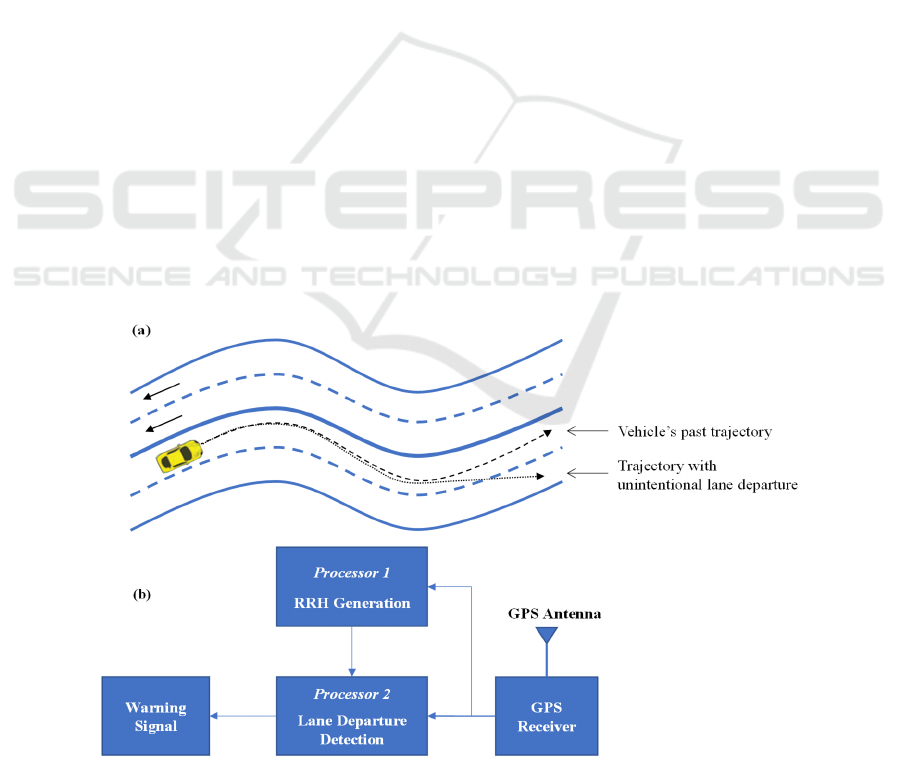
departure of a vehicle as illustrated in Figure 1a,
where the dashed line represents a vehicle’s past
trajectory which can be used to generate RRH for the
road to detect an unintentional lane departure e.g., as
represented by a dotted line in Figure 1a.
The architecture of the proposed system combining
the previously developed lane departure detection
method and the newly proposed RRH generation
algorithm is shown in Figure 1b where the GPS
receiver acquires longitude and latitude of a moving
vehicle’s position in real-time to be used by both
processors. The Processor 1 uses a sufficient length of
a GPS trajectory on a given road to generate an RRH
for that road using the newly developed algorithm.
Figure 1: (a) Conceptual diagram showing how a past trajectory (black dashed line) of a given vehicle can serve to generate
RRH to detect its unintentional lane departure in future (black dotted line), and (b) the system architecture of LDWS using
the newly proposed algorithm to generate RRH from a vehicle’s past GPS trajectories.
Generation of Road Reference Heading using GPS Trajectories for Accurate Lane Departure Detection
585

On the other hand, Processor 2 works in real-time
to detect unintentional lane departure using the
previously proposed lane departure detection method
except that it uses the RRH generated by Processor 1
using one or more past GPS trajectories as opposed to
the RRH extracted from an open-source low-
resolution map as was used in . The Processor 2 can
detect an unintentional lane departure of any vehicle
on a given road if the vehicle has been driven on that
road at least once before so that the necessary RRH
for that road has already been generated by Processor
1. Please note that the proposed algorithm is suitable
to be integrated into smartphone Apps e.g., Waze,
Google Maps, or Apple Maps to take advantage of the
vast database of multiple GPS trajectories of a
broader road network. This can enable any vehicle to
detect an unintentional lane departure on any road
even if the vehicle is driven on that road for the first
time.
3 RRH GENERATION
ALGORITHM
Any typical road segment may consist of a
combination of straight and curve road sections.
Usually, a road is not curved abruptly, therefore, a
transition section exists between a straight and a
curve section. The proposed algorithm to generate a
vehicle’s trajectory into a useful RRH works in three
stages. In the first stage, all straight, curve, and
transition sections of any road are identified from the
given GPS trajectory on that road. In the second stage,
each identified section is characterized with a set of
optimized parameters defining road reference
heading value at each point on that road section. In
the third stage, all individual road sections are
combined to obtain a composite RRH for that road.
3.1 Identification of Various Sections
The heading for a straight road section remains
constant while it changes uniformly for a curve
section. Similarly, the differential heading for a
straight section is zero while it has a non-zero
constant value for a curve section with larger values
for sharper curves. A typical vehicle trajectory
acquired by a standard GPS receiver consists of its
position coordinates at fixed time intervals (typically
every 100 msec). Any two consecutive position
coordinates of a moving vehicle on a given road can
be used to obtain heading and differential heading of
the road at that point.
The proposed algorithm uses differential heading
to identify various sections present in a given road by
first identifying all straight sections where differential
heading remains zero followed by curve sections
where differential heading is a non-zero constant. The
transition sections are identified at the end.
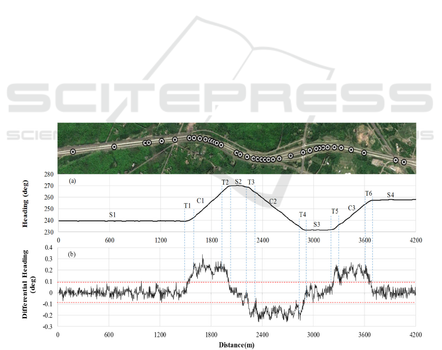
To illustrate the section identification process,
heading and differential heading calculated from a
typical GPS trajectory versus distance are shown in
Figure 2a and 2b, respectively. The GPS trajectory
was acquired using a standard GPS receiver with a
UBlox LEA-6 chipset on a 4.2 km section of
Interstate I-35 while driving at 70 MPH. The heading
at each point of the given road, calculated from a
vehicle’s GPS trajectory, exhibits a high-frequency
noise over distance caused by inherent GPS error
which is further accentuated in differential heading
values as shown in Figure 2b. This high-frequency
noise can be reduced by moving average method
using more than two consecutive GPS points for
heading and differential heading calculation. For the
proposed algorithm, a 9-point moving average was
used to reduce the standard deviation of differential
heading to 0.03
o
.
3.1.1 Identification of Straight Sections
Although the average differential heading of a
straight section is zero, the instantaneous differential
heading at any point of a straight section fluctuates
around zero due to GPS noise. This fluctuation
remains within the boundaries of ±0.09
o
or three
times the standard deviation of differential heading as
shown in Figure 2b. The proposed algorithm
identifies straight sections by comparing the
differential heading with a threshold of ±0.09
o
as
shown by dashed red line in Figure 2b. Whenever the
differential heading exceeds the threshold of ±0.09
o
in either direction, the crossing points are marked as
the beginning and ending points of the straight
sections of the road. All such points are shown by
vertical blue dashed lines in Figure 2, identifying a
total of four straight sections from the given trajectory
which are marked as S1, S2, S3, and S4.
There is no lane change present in the trajectory
of Figure 2. However, in reality, a vehicle may
change lanes while traveling on a multiple lane road.
The lane changes present in any given trajectory may
wrongfully be considered as road curvature on that
road. However, the differential heading during any
typical lane change does not exceed the threshold of
±0.09
o
. Therefore, the proposed algorithm can
correctly identify all straight sections of the road even
if lane changes are present in each trajectory.
VEHITS 2021 - 7th International Conference on Vehicle Technology and Intelligent Transport Systems
586
3.1.2 Identification of Curve Sections
There is usually a curve and two transition sections
present between any two consecutive straight
sections. To identify a curve section between any two
consecutive straight sections, the proposed algorithm
calculates a path average differential heading
(PADH) between the ending point of the first and
beginning point of the second of the two consecutive
straight sections.
The value of calculated PADH will be slightly
smaller than the true PADH value of the curve section
alone because this is calculated for the curve section
including the two adjoining transition sections on
each side of the curve as illustrated in Figure 3, where
a zoomed-in portion of the trajectory of Figure 2 is
reproduced showing only the first curve section
surrounded by two straight sections (S1 and S2) and
corresponding transition sections. To identify the
beginning and ending points of a curve section alone,
a set of two points between two consecutive straight
sections (one on each side) are identified where the
differential heading value is closest to the calculated
PADH.
The beginning and ending points of a curve
section identified this way will still not be the true
beginning and ending points of the curve because the
PADH value used to identify these points was
calculated for the curve section including the two
transition sections. Therefore, a second iteration of
the same routine is performed by calculating a new
PADH value between the two points identified in the
first iteration. The new PADH value calculated in the
second iteration is more likely to be closer to the true
PADH value of the curve section alone because it is
calculated for the curve section including only the
extreme ends of the transition sections on both sides.
This process can be repeated, however, beyond two
iterations, the beginning and ending points of a curve
section do not change significantly. Using this
method, all curve sections can be identified in any
given GPS trajectory. A total of three curve sections
(C1, C2, and C3) were identified in the given GPS
trajectory of Figure 2. Please note that the proposed
algorithm can correctly identify all curve sections in
a given trajectory even when a lane change is present
for the same reason as explained for straight section.
3.1.3 Identification of Transition Sections
After identifying the beginning and ending points of all
straight and curve sections, all remaining portions of
the trajectory are marked as transition sections. The
beginning and ending points of any transition section
will be the ending and beginning points of adjoining
straight and curve sections as shown for the transition
sections T1 and T2 in Figure 3. Similarly, all transition
sections in any given trajectory are identified.
Figure 2: (a) Vehicle heading and (b) differential heading vs. distance for a vehicle’s trajectory acquired by a standard GPS
receiver on a 4.2 km segment of Interstate I-35. The picture of Google Map of the relevant portion of the road is shown on
the top.
Generation of Road Reference Heading using GPS Trajectories for Accurate Lane Departure Detection
587
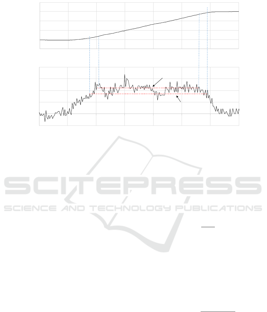
Figure 3: (a) Vehicle heading and (b) differential heading vs. distance for a small portion of the trajectory of Figure 2. This
portion includes a part of first straight section, S1, T1, C1, T2, and a part of S2.
3.2 Characterization of Various
Sections
After identifying all individual sections of the road
from a given trajectory, each section is characterized
separately with a proper set of parameters to define
RRH at each point of the given road section. Each
straight section is characterized with a path average
heading (PAH) as heading remains the same for the
entire length of a straight section. Similarly, heading
of a curve section changes uniformly with distance,
therefore, it is characterized with a path average
heading slope (PAHS) and an initial heading (IH) i.e.,
the heading at the beginning point of the curve section
to completely define RRH at each point of the curve
section. For a transition section, heading neither
remains the same as in a straight section nor does it
change uniformly with distance as in a curve section
suggesting that a transition section should be
characterized as a second-order polynomial.
However, the length of a typical transition section is
usually too small to characterize it as a second-order
polynomial. Furthermore, the incremental accuracy
of RRH with a second-order characterization is
negligibly small. Therefore, the proposed algorithm
characterizes each transition section just like a curve
section i.e., with IH and PAHS values. Please note
that the PAHS value of a transition section is different
from the PAHS value of the adjoining curve section.
3.2.1 Characterization of Straight Sections
Each straight section is initially characterized with a
PAH value, between the beginning and ending points
of a straight section, calculated using equation 1,
where h
n
is the vehicle heading between any given
point n and its previous point, and d
n
is the distance
between the two points.
𝑃𝐴𝐻=
∑
∑
(1)
However, the initially assigned value of PAH for
any given straight section may not be the optimal
value. To find the optimal value of PAH for a straight
section, the heading error between the vehicle
heading and PAH should be minimized. The value of
PAH is varied in small increments around its initially
assigned value and root mean square of heading error
(RMSHE) is calculated for each value of PAH using
equation 2, where h
ref
is the RRH i.e., PAH for a
straight section.
𝑅𝑀𝑆𝐻𝐸 =
〈
ℎ
−ℎ
〉
(2)
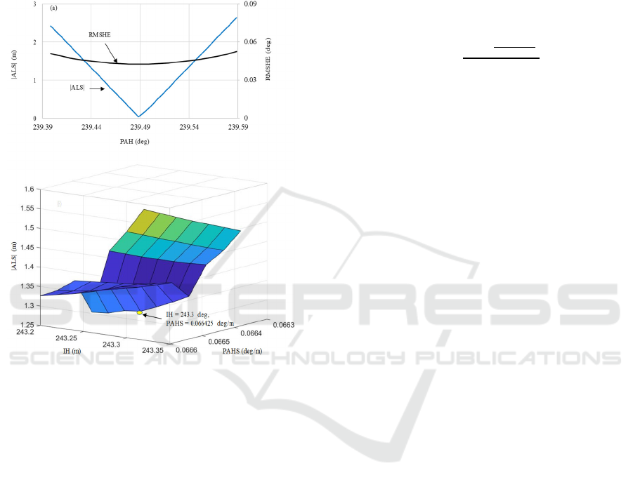
The RMSHE for the first straight section (S1) of
Figure 2 is shown in Figure 4a for varying values of
PAH. The RMSHE remains almost flat for a wide
range of PAH values suggesting that optimal value of
PAH is not very sensitive to small changes. Although
minimizing RMSHE would result in an optimized
-0.1
0
0.1
0.2
0.3
0.4
1400 1500 1600 1700 1800 1900 2000 2100
Differential Heading (deg)
Distance(m)
230
240
250
260
270
280
1400 1500 1600 1700 1800 1900 2000 2100
Heading (deg)
S
1
S
2
C
1
T
1
T
2
PADH of curve &
transition sections
PADH of curve section
only
VEHITS 2021 - 7th International Conference on Vehicle Technology and Intelligent Transport Systems
588
value of h
ref
for a given straight section, the objective
at hand is to minimize ALS for each section because
ALS is to be used to detect unintentional lane
departure (Faizan et al. 2019). Therefore, the absolute
value of ALS (|ALS|) is also calculated by varying
PAH value for each straight section using equation 3.
|𝐴𝐿𝑆| =
∑
𝑑
𝑠𝑖𝑛 (ℎ
−ℎ
) (3)
Figure 4: (a) RMSHE and |ALS| vs. PAH for the straight
section S1 showing optimal value of PAH, and (b) a surface
plot of |ALS| vs. IH and PAHS for the curve section C1
showing optimal combination of IH and PAHS values.
The calculated value of |ALS| for different PAH
values around its initially assigned value for the
section S1 is also shown in Figure 4a, along with
RMSHE values, revealing a clear minimum. The
optimal value of PAH (239.50
o
) not only minimizes
|ALS| but also falls within the flat minimum range of
RMSHE. The same general trend was true for all
straight sections of the trajectory. Using this method,
any straight section can be characterized with an
optimal value of PAH.
Please note that the heading can change
significantly as opposed to differential heading
during a lane change present in a trajectory.
Therefore, the optimal value of PAH can be adversely
affected for a straight section if a lane change is
present. The proposed algorithm can detect the
location and span length of such a lane change and
optimize the PAH value excluding the lane change
portion of the section.
3.2.2 Characterization of Curve Sections
As described earlier, each curve section is
characterized with two parameters, i.e., IH and
PAHS. An initial value of IH is assigned as the
heading at the beginning point of any curve section
and the initial value of PAHS is assigned using
equation 4, where h
n
is the heading between any given
point n and its previous point, and h
n-1
is the heading
between point n-1 and its previous point.
𝑃𝐴𝐻𝑆 =
(∑
)
∑
(4)
After initial values are assigned to both IH and
PAHS for a curve section, they are optimized by
minimizing |ALS| by varying both IH and PAHS
values in small increments around their initially
assigned values. The optimization process is
illustrated in Figure 4b, where |ALS| is plotted versus
IH and PAHS as a surface plot for the curve section
C1. Please note that the resulting optimal values of IH
and PAHS are 243.30
o
and 0.066425 deg/m,
respectively, and are noticeably different from their
corresponding initially assigned values (243.26
o
and
0.066475 deg/m). Using the same method, all other
curve sections are optimized. Please note that the
optimization of a curve section in the presence of a
lane change is performed the same way as described
for straight section.
3.2.3 Characterization of Transition
Sections
As discussed earlier, each transition section is
characterized as it is a curve section. Therefore, it
should be initially assigned with two parameters, i.e.,
IH and PAHS, and their optimization process should
be like that of a curve section. However, if both
parameters are optimized independently then there is
a possibility of an abrupt change of heading at corner
points where transition section adjoins a straight or a
curve section. This is because the end points of any
transition section are the same as the beginning and/or
ending points of adjoining straight and/or curve
sections. Therefore, the characterization of transition
section is more straightforward. The optimized
heading at the ending point of the preceding straight
or curve section is considered as the IH value of the
transition section. Similarly, an optimal value of
PAHS for a transition section is calculated using the
optimized values of heading at the two end points of
the transition section.
Generation of Road Reference Heading using GPS Trajectories for Accurate Lane Departure Detection
589
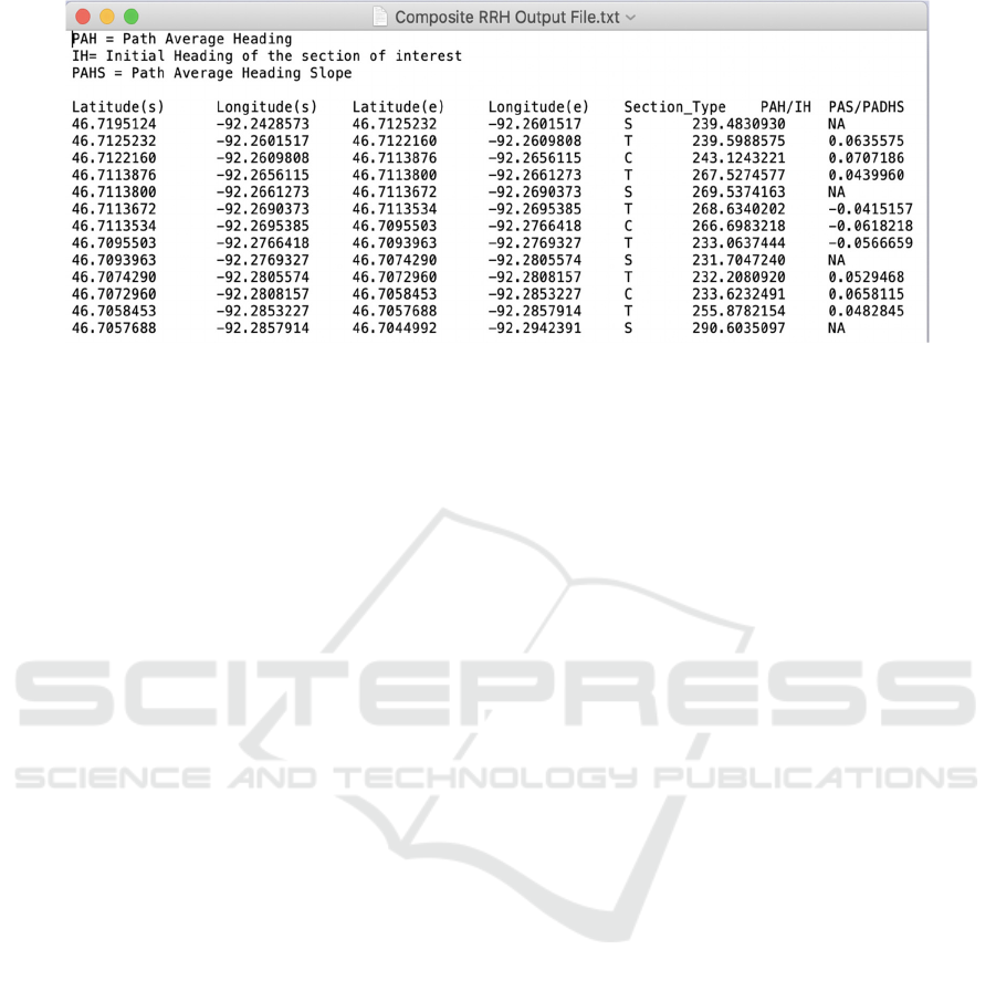
Figure 5: Screen shot of a typical output file containing optimized parameters of each section in the composite RRH.
3.3 Combining All Sections to Generate
a Composite RRH
After identifying and characterizing each section with
an optimal set of parameters, all sections are
combined to generate a composite RRH for that road.
The typical output file generated by the algorithm is
shown in Figure 5, where each row represents an
individual section of the road defined by its beginning
and ending points (in terms of latitude and longitude),
the optimized parameter values, and the section type.
Please note that an “N” indicates that the
corresponding parameter is not applicable to that
section. This file has the necessary information to
completely define the RRH at any point along the
road and can be used to detect an unintentional lane
departure in real-time using previously proposed lane
departure detection method.
A composite RRH generated from a single
trajectory may not be accurate for all future
trajectories because usually, a vehicle will take a
slightly different trajectory in each new trip on the
same road. However, multiple composite RRHs
obtained from different vehicle trajectories for a
given road can be combined to obtain an average
composite RRH. The combination of two or more
composite RRHs generated from different individual
GPS trajectories is achieved in two steps. First, every
optimized parameter of each straight and curve
section is combined using a simple average method.
Second, the beginning and ending points of each
straight and curve section are combined by averaging
the latitude and longitude values of the beginning and
ending points, separately.
After combining all straight and curve sections,
transition sections are automatically combined
because the beginning and ending points of all
transition sections are the same as the beginning and
ending points of adjoining straight and/or curve
sections as described earlier. Using the same
averaging method, each additional composite RRH
generated from a future vehicle trajectory can be
added to an already existing average composite RRH
to improve its accuracy over time.
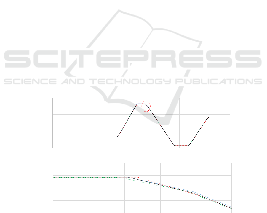
The proposed algorithm was applied to many
vehicle trajectories on the same road segment of
Interstate I-35 and a composite RRH was generated
from each trajectory. Three such composite RRHs
generated from three different trajectories on the
same road and the average composite RRH are shown
in Figure 6a where heading versus distance is plotted
across the entire 4.2 km length.
The difference in heading values of multiple
composite RRH is not visible in Figure 6a because of
the large variation of heading over the span of the
road segment. To highlight the difference in different
composite RRH values, a zoomed-in portion of
Figure 6a marked by a red dashed circle is shown in
Figure 6b. The zoomed-in portion includes the right-
side portion of S2, entire T2, and the left side portion
of C2 sections of the road where the difference in
heading values of each composite RRH is more
pronounced showing the averaging effect.
4 FIELD TESTS AND RESULTS
The main purpose of the proposed algorithm is to
generate an average composite RRH from multiple
vehicle trajectories for a given road to accurately
detect unintentional lane departure in real-time using
the previously developed lane departure detection
method by calculating ALS at any given point on the
road using equation 5, where h
ref,k
is the RRH value at
the current point, n, of the road.
VEHITS 2021 - 7th International Conference on Vehicle Technology and Intelligent Transport Systems
590
𝐴𝐿𝑆=
∑
𝑑
sin (ℎ
−ℎ
,
)
(5)
When a vehicle unintentionally drifts away from
its lane, ALS starts to increase in value (positive or
negative), and once its value increases beyond a
certain threshold (±1m), an unintentional lane
departure is detected initiating a warning for the
driver. Please note that ALS will also increase in
value if a vehicle intentionally changes its lane. An
intentional lane change can be distinguished from an
unintentional lane departure by the presence or
absence of turn signal.
In case of an intentional lane change, the increase
in ALS begins to saturate upon completion of lane
change because the vehicle starts to travel again in
parallel to the RRH of the road. As a result of normal
driving behaviour, this phenomenon i.e., the
saturation of ALS can also occur in case of an
unintentional wandering within a lane while ALS
values remain within the ±1m threshold. This
phenomenon is used to reset the value of ALS to zero
whenever its value begins to saturate.
The accuracy of the lane departure detection
method depends upon the accuracy of the composite
RRH for that road. To evaluate its accuracy, field tests
were performed by driving a test vehicle multiple
times on the same 4.2 km segment of Interstate I-35
for which an average composite RRH was already
generated using the newly proposed algorithm. The
test vehicle was driven at about speed limit (70 MPH)
on this 4-lane freeway and many back-and-forth lane
changes were made intentionally during the field
tests. For safety reasons, intentional lane changes
were made to test the accuracy of lane departure
detection using the composite RRH generated by the
newly proposed algorithm.
For each trip, ALS was calculated in real-time to
detect any lane departure. The vehicle heading for one
such test trip vs. distance is plotted along with the
RRH of the road segment in Figure 7a showing that
vehicle heading deviates from the RRH during each
lane change as expected. The corresponding ALS vs.
distance is plotted in Figure 7b showing that ALS
exceeds ±1m threshold during each lane change. A
total of ten right and left lane changes were made in
this trip and all lane changes were detected accurately
and in a timely manner. A digital mask for lane
departure detection warning signal is plotted as a
dashed red line showing the start and end of each lane
change in Figure 7b. Lane departure warning signal
becomes active when ALS exceeds the ±1m threshold
and is deactivated when the vehicle heading becomes
parallel to RRH of the road. In multiple field tests,
more than 100 lane changes were made, and each lane
change or lane departure was accurately and timely
detected. Furthermore, nowhere else along the
trajectory, ALS exceeded the threshold i.e., no false
alarm was observed.
To test the frequency of the false alarms, the test
vehicle was also driven multiple times on the same
road segment without making any lane changes. In
more than 10 trips on the 4.2 km long route, no false
alarm was observed as indicated in Figure 7c, where
ALS is plotted vs. distance for four such test trips.
Figure 6: (a) Heading of average composite RRH and three individual composite RRH obtained from three different vehicle
trajectories of 4.2 km segment of Interstate I-35, and (b) zoomed portion of (a) highlighted by red dashed circle.
230
245
260
275
0 600 1200 1800 2400 3000 3600 4200
Heading (deg)
(b)
264
266
268
270
272
2100 2140 2180 2220 2260 2300
Heading (deg)
Distance (m)
Composite RRH 1
Composite RRH 2
Composite RRH 3
Avg. Composite RRH
Generation of Road Reference Heading using GPS Trajectories for Accurate Lane Departure Detection
591
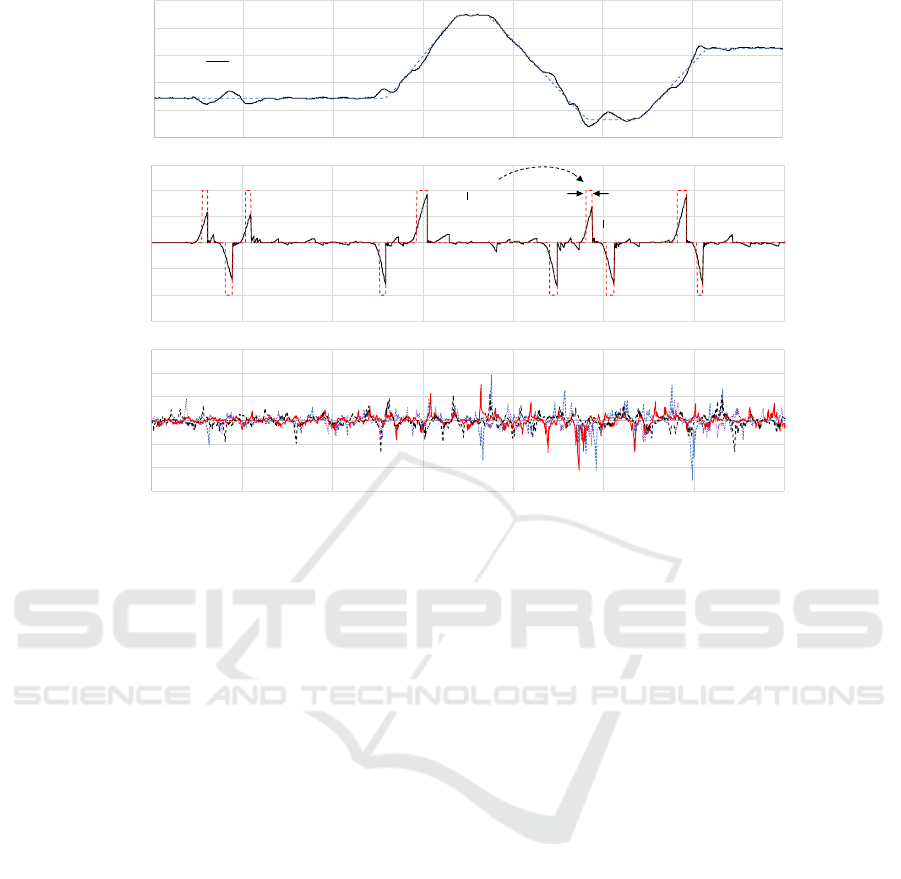
Figure 7: (a) Vehicle heading and RRH vs travelled distance for one test trial, (b) ALS versus travelled distance of the
corresponding test trial trajectory, and (c) ALS versus distance on the same 4.2 km segment of Interstate I-35 for four typical
trial trajectories with no lane change.
Furthermore, ALS value along any point on the road
remained below ±0.3m which is well below the ±1m
threshold, showing that the composite RRH generated
from past vehicle trajectories significantly improves
the accuracy of previously proposed lane departure
detection method by practically reducing the
frequency of false alarms to zero with a lot of margins
to spare.
5 CONCLUSIONS
In this paper, a novel algorithm is proposed to
generate an accurate RRH for any given road from a
vehicle’s past trajectories on that road. The newly
proposed algorithm can be applied to large tracts of a
vehicle trajectory to generate an accurate RRH for
that road regardless of whether a lane change is made
during acquisition of the trajectory. The newly
proposed algorithm was implemented to obtain RRH
for multiple roads and integrated with the previously
developed LDWS to test its ability to accurately
detect unintentional lane departures. Field test results
show that the newly proposed algorithm accurately
detects any unintentional lane departure as well as
minimizes the number of false alarms to almost zero
which was the prime objective while designing the
newly proposed algorithm. Successful development
of the proposed algorithm will pave the way for
integration of the algorithm into one of the popular
smartphone Apps.
ACKNOWLEDGEMENTS
The authors wish to acknowledge those who made
this research possible. The study was funded by the
Minnesota Department of Transportation (MnDOT)
and Minnesota Local Research Board (LRRB).
REFERENCES
Driving down lane-departure crashes: A national priority,
American Association of State Highway and
Transportation Officials, Washington DC, 2008.
Cicchino, J. Effects of lane departure warning on police-
reported crash rates, Journal of Safety Research, 2018.
Volume 66, pp.61-7.
Salvucci, D. D. Inferring driver intent: A case study in lane-
change detection. Proc. Human Factors Ergonomics
Society 48th Annu. Meeting, New Orleans, LA, 2004.
pp. 2228–2231.
-6
-4
-2
0
2
4
6
0 600 1200 1800 2400 3000 3600 4200
Accumulated Lateral Shift (m)
(a)
(b)
225
235
245
255
265
275
0 600 1200 1800 2400 3000 3600 4200
H
ea
di
ng
(d
eg
)
Vehicle Direction of Travel
Lane Departure Warning Duration
-0.3
-0.2
-0.1
0
0.1
0.2
0.3
0 600 1200 1800 2400 3000 3600 4200
Accumulated Lateral Shift (m)
(c)
(b)
Distance (m)
--- Road Reference Heading
VEHITS 2021 - 7th International Conference on Vehicle Technology and Intelligent Transport Systems
592

Kuge, N., T. Yamamura, and O. Shimoyama. A Driver
Behavior Recognition Method Based on a Driver
Model Framework, Warrendale, PA: Soc. Automot.
Eng., 1998.
McCall, J., and M. M. Trivedi. Visual context capture and
analysis for driver attention monitoring. Proc. IEEE
Conf. Intelligent Transportation Systems, Washington,
DC, 2004. pp. 332–337.
Heimes, F., and H. H. Nagel. Towards active machine-
vision-based driver assistance for urban areas. Int. J.
Comput. Vision, 2002. vol. 50, no. 1, pp. 5–34.
Kwon, W., and S. Lee. Performance evaluation of decision-
making strategies for an embedded lane departure
warning system. J. Robot. Syst., 2002. vol. 19, no. 10,
pp. 499–509.
An, X., M. Wu and H. He. A Novel Approach to Provide
Lane Departure Warning Using Only One Forward-
Looking Camera. International Symposium on
Collaborative Technologies and Systems (CTS'06),
2006. pp. 356-362.
Hsiao, P., and Chun-Wei Yeh. A Portable Real-Time Lane
Departure Warning System based on Embedded
Calculating Technique. IEEE 63rd Vehicular
Technology Conference, Melbourne, Vic., 2006. pp.
2982-2986.
Yu, B., W. Zhang and Y. Cai. A Lane Departure Warning
System Based on Machine Vision. IEEE Pacific-Asia
Workshop on Computational Intelligence and Industrial
Application, Wuhan, 2008. pp. 197-201.
Leng, Y. C., and C. L. Chen. Vision-based lane departure
detection system in urban traffic scenes. 11th
International Conference on Control Automation
Robotics & Vision, Singapore, 2010. pp. 1875-1880.
Lindner, P., E. Richter, G. Wanielik, K. Takagi and A.
Isogai. Multi-channel lidar processing for lane
detection and estimation. 12th International IEEE
Conference on Intelligent Transportation Systems, St.
Louis, MO, 2009. pp. 1-6.
McCall, J. C., and M. M. Trivedi. Video-based lane
estimation and tracking for driver assistance: survey,
system, and evaluation. IEEE Transactions on
Intelligent Transportation Systems, 2006. vol. 7, no. 1,
pp. 20-37.
Daimler Chrysler AG. Vehicle with Optical Scanning
Device for a Lateral Road Area. US006038496a, 2018.
Clanton, J. M., D. M. Bevly and A. S. Hodel. A Low-Cost
Solution for an Integrated Multisensor Lane Departure
Warning System. IEEE Transactions on Intelligent
Transportation Systems, 2009. vol. 10, no. 1, pp. 47-59.
Muhammad Faizan, S. Hussain and M.I. Hayee, Design
And Development Of In-vehicle Lane Departure
Warning System Using Standard GPS Receiver.
Transportation Research Record, Journal of
Transportation Research Board, I-9, 2019.
Cao, L., and J. Krumm. From GPS traces to a routable road
map. GIS: Proceedings of the 17th ACM SIGSPATIAL
International Conference on Advances in Geographic
Information Systems, 2009. pp. 3–12.
Guo,T., K. Iwamura, M. Koga. Towards high accuracy
road maps generation from massive GPS Traces data.
IEEE International Geoscience and Remote Sensing
Symposium, Barcelona, Spain, 2007.
Chen, C., and Y. Cheng. Roads Digital Map Generation
with Multi-track GPS Data. International Workshop on
Education Technology and Training & International
Workshop on Geoscience and Remote Sensing,
Shanhai, China, 2008.
Guo, D., S. Liu, H. Jin. A graph-based approach to vehicle
trajectory analysis. Journal of Location Based Services,
2010. Volume 4.
Shi, W., S. Shen, and Y. Liu. Automatic generation of road
network map from massive GPS, vehicle trajectories.
12th International IEEE Conference on Intelligent
Transportation Systems, St. Louis, MO, USA, 2009.
Huang, J., M. Deng, J. Tang, S. Hu, H. Liu, S. Wariyo,
and J. He. Automatic Generation of Road Maps from
Low Quality GPS Trajectory Data via Structure
Learning. IEEE Access (Volume – 6), 2018.
Generation of Road Reference Heading using GPS Trajectories for Accurate Lane Departure Detection
593
