
A Direct Formal Semantics for BPMN Time-related Constructs
Sara Houhou
1,2,3 a
, Souheib Baarir
1,4
, Pascal Poizat
1,4 b
and Philippe Qu
´
einnec
5
1
Sorbonne Universit
´
e, CNRS, LIP6, F-75005, Paris, France
2
LINFI Laboratory, Biskra University, Biskra, Algeria
3
Montpellier Universit
´
e, CNRS, LIRMM, F-34000, Montpelier, France
4
Universit
´
e Paris Lumi
`
eres, Universit
´
e Paris Nanterre, F-92000, Nanterre, France
5
IRIT, Universit
´
e de Toulouse, F-31000 Toulouse, France
Keywords:
BPMN, Timed Models, Workflows, Collaborations, Formal Verification, Alloy, Tool.
Abstract:
BPMN supports the design of intra-organization workflows and inter-organization collaborations. This rich
notation includes elements to deal with models where time is central. However, the expressiveness of the
BPMN time-related constructs hampers the definition of a formal semantics including them, and the provision
of formal analysis means for timed process models. We propose here a first-order logic semantics for a subset
of BPMN that includes its time-related constructs. With reference to related work, we support the specification
of datetimes, durations, and cycles, using ISO-8601 formats as specified in the standard. Our approach is
tool-supported by a model transformation into the Alloy formal language and its bounded counter-example
generator. Our tool and model database are open source and freely available.
1 INTRODUCTION
A Business Process (BP) is a set of activities that are
organized in order to reach some objective. Busi-
ness Process Modeling Notation(BPMN) enables one
to model both single processes using workflows but
also collaborations where communication coordinates
processes in different organizations. In both cases,
time can play a part in the way the process(es) ex-
ecute, e.g., with deadlines before which one has to
agree on a commercial offer or with sub-processes be-
ing regularly started after some duration.
To support this, BPMN defines a set of time-
related events: timer start events (TSE) – to start some
process, timer intermediary catch events (T ICE) –
to wait for some condition to be fulfilled, and timer
boundary events (T BE), interrupting or not, to stop
an activity or run a parallel one. All three kinds of
events depend on a time-related condition defined in
their TimerEventDefinition (OMG, 2013).
There are also three kinds of TimerEventDefi-
nitions: timeDate (at some date-time, e.g., at 5:30
pm on March, 24th, 2020), timeDuration (after some
amount of time, e.g., after 1 hour and 30 minutes),
a
https://orcid.org/0000-0002-4166-0609
b
https://orcid.org/0000-0001-7979-9510
and timeCycle (repeated several times, with a dura-
tion between each instance and possibly after/before
a given date-time, e.g., after 1 hour and 30 minutes, 3
times, starting from 5:30 pm on March, 24th, 2020).
To give the associated piece of information, BPMN
relies on the ISO-8601 standard (ISO8601, 2004). Ta-
ble 1 gives a synthetic view of time-related events
in BPMN w.r.t. the ISO-8601 standard. No explicit
formal semantics for BPMN time-related features is
given in the standard. Further, the ISO-8601 descrip-
tion of time information is quite complex. This makes
it more difficult to perform formal analysis of process
models before, e.g., running them on process engines.
In addition, a lot of effort has been done to iden-
tify the most common time-related scenarios from a
business perspective, leading to Process Time Pat-
terns (Lanz et al., 2010; Lanz et al., 2014; Lanz
et al., 2016). Formally assessing the suitability of
BPMN to support these patterns is desirable. How-
ever, this requires first to define a formal operational
semantics for time-related features in BPMN. This is-
sue has been addressed in several proposals (see Sec-
tion 5). Still, these proposals often leave apart several
features related to time-related events in the broader
sense (Tab. 1).
Contribution. In a previous work (Houhou et al.,
2019), we have defined a formal semantics for a sub-
138
Houhou, S., Baarir, S., Poizat, P. and Quéinnec, P.
A Direct Formal Semantics for BPMN Time-related Constructs.
DOI: 10.5220/0010462901380149
In Proceedings of the 16th International Conference on Evaluation of Novel Approaches to Software Engineering (ENASE 2021), pages 138-149
ISBN: 978-989-758-508-1
Copyright
c
2021 by SCITEPRESS – Science and Technology Publications, Lda. All rights reserved

Table 1: Time-related features in BPMN and their relation to ISO-8601, support: BPMN and us (•), BPMN only (◦).
BPMN Standard
TSE TICE
TBE TBE
TimerEventDefinition ISO-8601 Interrupt non-Interrupt
timeDate date and time yyyy-mm-ddThh:mm:ssZ • • • •
timeCycle
unbounded
R/ yyyy-mm-ddThh:mm:ssZ / yyyy-mm-ddThh:mm:ssZ ◦ ◦ – ◦
R/ yyyy-mm-ddThh:mm:ssZ / PnYnMnDTnHnMnS ◦ ◦ – •
R/ PnYnMnDTnHnMnS/yyyy-mm-ddThh:mm:ssZ ◦ ◦ – •
R/PnYnMnDTnHnMnS ◦ ◦ – •
bounded
Rn/ yyyy-mm-ddThh:mm:ssZ/yyyy-mm-ddThh:mm:ssZ ◦ ◦ – ◦
Rn/ yyyy-mm-ddThh:mm:ssZ/PnYnMnDTnHnMnS ◦ ◦ – •
Rn/ PnYnMnDTnHnMnS/yyyy-mm-ddThh:mm:ssZ ◦ ◦ – •
Rn/ PnYnMnDTnHnMnS ◦ ◦ – •
timeDuration duration PnYnMnDTnHnMnS – • • •
set of BPMN (Fig. 1, but for time-related events), with
a focus on BPMN communication constructs and dif-
ferent communication models. We also had defined
a tool, fbpmn, to support the formal analysis of pro-
cesses, and generate and animate counter examples.
In the paper at hand, we extend this work by support-
ing the expressive time-related features of BPMN, in-
cluding the use of the ISO-8601 standard, and show
how we can support the Process Time Patterns. The
proposed semantics is directly defined in terms of
First-Order Logic (FOL), rather than through a map-
ping to some formal language. This choice makes it
possible for researchers to map the FOL semantics
to verification frameworks of their choice like (Al-
loy with SAT solvers) as we did here; TLA+ with the
TLC model-checker (as we did before), SMT, or oth-
ers). To support the formal verification of processes,
we translate the proposed semantics in Alloy.
Case Study. Fig. 2 presents a BPMN diagram of a
simplified reviewing procedure for a scientific paper
in a special issue of a journal. The scenario involves
three participants that act in a collaboration diagram
which are PC chair, Author, Reviewer. For simpli-
fication, we consider only one author and only one
reviewer. This model is elaborated based on the fol-
lowing scope statements:
• The author sends a paper to the Journal PC Chair
through the submit paper send task. Then, he/she
will wait until the arrival of the notification re-
sponse. If he/she doesn’t receive a notification
by ”2021-09-18 T 00:00” the author withdraws
his/her paper.
• The PC Chair starts when the specified date
and time, ”2021-01-17 T 00:00”, of the CFP is
reached. This is reflected by the timer start event
of the process at the Journal PC Chair. Then, it
waits for submissions. The receive activity is au-
thorized until the specified close date, given as
”2021-03-17 T 00:00”. When the process receives
a research paper, he/she assigns it to a reviewer via
the send task ”assign paper”. To avoid delay for
the response review process, he/she sends before
the deadline date a reminder two times in a period
of 15 days between. This is reflected by a non
interrupting boundary time event associated with
the receive review task, ”R2/ P15D / 2020-04-29
T 00:00:00”.
• The Reviewer process receives a Review Request
message to starts. The reviewer starts preparing a
review, and he/she sends it back to the PC Chair
when it is ready.
• After the PC Chair has received a review, he/she
prepares the acceptance/rejection letter, or a bor-
derline letter if the paper requires further improve-
ments. Then, he/she attaches the review to the no-
tification letter and sends it to the author at the
notification date and time specified in the CFP
(”2021-05-16 T 00:00”). Even if the PC Chair has
reached a decision before that date, he/she waits
for this date before sending the notification. This
is reflected by an intermediate timer event.
Overview. The remainder of this paper is structured
as follows. Section 2 gives an informal overview
of the BPMN execution semantics, including time-
related features. Section 3 then details our proposed
formalization for them. The implementation of our
semantics in Alloy, verification, and evaluation are
discussed in Section 4. We end up with a compari-
son to related work in Section 5 and a conclusions in
Section 6.
2 OVERVIEW OF THE BPMN
EXECUTION SEMANTICS
In this section we informally survey the semantics
of the BPMN elements that we support (Fig. 1). To
maintain traceability with the standard, we use a
token-based approach, with tokens on both nodes and
edges. We define an execution model based on two
predicates, Start (St) and Complete (Ct). Their defi-
nition depends on the BPMN element taken in con-
sideration. In the next section we give the formal
A Direct Formal Semantics for BPMN Time-related Constructs
139

Events (E)
Start Events (SE)
NSE MSE
Intermediate Events (IE)
CMIE
TMIE
End Events (EE)
NEE MEETEE
Gateways (G)
AND
XOR
OR
EB
Nodes
Pool Lane (P)
Activities (A)
Sub Process, expanded (SP)
Tasks (T)
AT RT ST
Boundary Events (BE)
MBE
MBE (non interrupt.)
Pool Lane (P)
RT
ST
Sequence Flows (SF)
Edges
NSF CSF DSF MF
TSE
TICE
TBE
TBE (non interrupt.)
Figure 1: Subset of BPMN being taken into consideration in our work.
definition for time-related features, together with ac-
tivities (tasks and sub-processes) and the event-based
gateway, since time has an impact on their semantics.
The semantics for the other BPMN constructs is kept
from (Houhou et al., 2019).
Starting and Terminating. Three kinds of events
are used for the starting of a process
1
: none (NSE),
message (MSE), and timer (T SE) start events. All
three are defined only through completion predicates.
They complete by initiating the process to which they
belong and by generating a token on their outgoing
edges. MSE and T SE are only ready to complete if
(i) they are active and, respectively, (ii) a specified
message has arrived on one of their incoming mes-
sage flow edges, or the (global) clock has reached a
given deadline. Two kinds of events are used for the
termination of a (sub-)process: none (NEE) and ter-
minate (T EE) end events. They start by moving a to-
ken from one of their incoming edges to themselves.
A T EE has an additional behavior. It drops down all
the remaining tokens of the process or sub-processes
to which it belongs.
Activities. They are the main working units in a pro-
cess. We make the distinction between a composite
activity, or Sub-Process (SP), and an atomic activ-
ity, or Task (T ). The latter can be an abstract (AT),
send (ST ), or receive (RT ) task. All activities have
the same basic behavior. They start by moving a to-
ken from an incoming edge to themselves. When the
activity is associated to a timer event, it does some
additional work that we will specify in the next para-
graphs.
Gateways. They are used to manage the control flow
of a process. A gateway can be Parallel (AND) to
1
NSE can also be used to start a sub-process.
model the simultaneous execution of all control flows
in a set, Inclusive (OR) to model the simultaneous ex-
ecution of a subset of control flows in a set, Exclu-
sive (XOR) to model the choice of one control flow in
a set, or Event-Based (EB) to model the choice of one
control flow in a set, based on external event triggers
(message or time conditions). An EB gateway is a
kind of deferred choice since its completion depends
on external events. It completes by moving the token
it owns on the triggered event outgoing edge. In this
paper we focus on EB gateways due to the importance
of priority aspects in their formal execution semantics
in presence of time-related features.
Intermediate Events. They are events that can oc-
cur during the process execution. In our work, we
consider the Message and Timer intermediate events.
For the Message ones, we support message catch-
ing (CMIE), message throwing (T MIE), and bound-
ary (interrupting or not) message (MBE) events. For
the Timer ones, that constitute the focus of this work,
we support the following:
• Timer Intermediate Catch Events (T ICE) that act
as a delay mechanism configured either by a du-
ration (T ICE
p
2
) or a fixed date (T ICE
d
). Such an
event waits for the specified duration or date be-
fore letting the control flow on which it is located
continue.
• Timer Boundary Events (T BE) that are attached
to an activity. Such an event can be either
interrupting (T BE
), i.e., it interrupts the run-
ning of the activity it is attached to, or non-
interrupting (T BE
⊕
). The start of an activity with
2
In TICE
p
, p stands for period as in the ISO-8601 stan-
dard for durations.
ENASE 2021 - 16th International Conference on Evaluation of Novel Approaches to Software Engineering
140
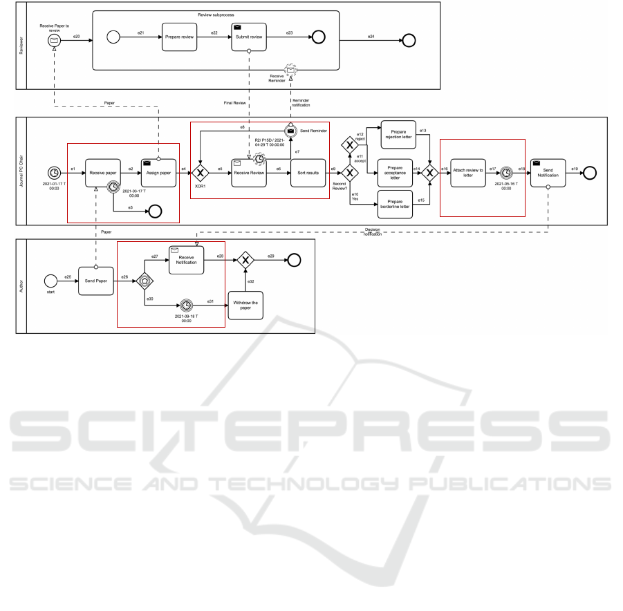
Zone 1
Zone 2
Zone 3
Zone 4
Figure 2: Paper Reviewing case study.
timer boundary events causes the activation of lo-
cal clocks for the boundary events attached to it.
– A T BE
acts as a deadline for an activity. If the
activation token remains on the activity more
than a specific duration, or fixed date, the timer
event interrupts the activity it is attached to.
We separate T BE
d
and T BE
p
: A T BE
d
is
a T BE
configured with a date, while a T BE
p
is configured with a duration.
– A T BE
⊕
can be configured with a
date (T BE
⊕
d
), a duration (T BE
⊕
p
), or a
time cycle (T BE
⊕
c
). T BE
⊕
d
and T BE
⊕
p
de-
fine the same behavior as T BE
d
and T BE
p
(respectively), without cancelling the activity
they are attached to. T BE
⊕
c
might be triggered
multiple times while the activity it is attached
to is active. The number of cycles can either be
fixed or unbounded. The time cycle definition
associated to a timer event may have different
configurations: (i) T BE
⊕
c(start)
defines a number
of recurrences for the timer event triggers
separated by a period and where the first
trigger is done relatively to a fixed start date;
(ii) T BE
⊕
c(end)
defines a number of recurrences
for the timer event triggers separated by a
period and where the last trigger is done before
the fixed end date; (iii) T BE
⊕
c(p)
defines a
number of recurrences for the timer event
triggers separated by a period.
3 BPMN TIME FORMALISATION
In this section we extend the formal semantics that
we proposed in (Houhou et al., 2019), to handle time
constructs with associated ISO-8601 time informa-
tion. We rely on a (typed) graph representation of
the workflow and collaboration models where types
correspond to kinds of BPMN elements as given in
Fig. 1 and Section 2, e.g., T BE for Timer Boundary
Events and T BE
p
for interrupting Timer Boundary
Events with a duration information. Roughly speak-
ing, We consider two sets of basic elements types:
Nodes, noted by T
Nodes
and Edges, noted by T
Edges
as
follows:
• T
Nodes
= {NSE,MSE,T SE,CMIE,T MIE,MBE,
T SE, NEE,T EE,MEE,XOR,OR,EB, AND,
AT, ST,RT,SP} ∪ T ICE ∪ T BE, where:
– T ICE = {T ICE
p
,T ICE
d
}
– T BE = T BE
∪ T BE
⊕
, with
*
T BE
= {T BE
d
,T BE
p
}
*
T BE
⊕
= {T BE
⊕
d
,T BE
⊕
p
} ∪ T BE
⊕
c
, with
T BE
⊕
c
= {T BE
⊕
c(start)
,T BE
⊕
c(start)
,T BE
⊕
c(p)
}
• T
Edges
= {NSF,CSF, DSF,MF}
3.1 Syntax
A BPMN model is seen as a typed graph (Def. 1),
where types corresponding to the BPMN elements are
A Direct Formal Semantics for BPMN Time-related Constructs
141

associated to nodes and edges. The BPMN standard
defines three time categories: timeDate, that speci-
fies a fixed date and time, timeCycle, that specifies
repeating intervals, and timeDuration, that specifies
the amount of time a timer should run before firing.
Formally, we define three time categories, Ctime =
{T
date
,T
duration
,T
cycle
}, and the following time struc-
tures to characterize the time constraints, timeVal =
Date ∪ Duration ∪Cycle:
• Date ⊆ N represents a date (and time) expressed
in seconds with respect to a reference date (1970-
01-01T00:00:00Z). Date refers to the timeDate
of the BPMN standard. A date like 2020-12-
03T13:52:33Z in ISO-8601 format is converted to
1,607,003,553 seconds.
• Duration ⊆ N represents a time duration in sec-
onds. This corresponds to the timeDuration of the
BPMN standard. A P3DT15M duration in ISO-
8601 format (3 days and 15 minutes) is converted
to 259,215 seconds. Note that we do not support
years and months in durations due to the ambigu-
ity of their correspondence in seconds.
• Cycle = (N ∪ {ι}) × [Duration ∪ (Date ×
Duration) ∪ (Duration × Date)], represents a
composite timing type. It defines time redundan-
cies along with a time duration, a fixed start date
and time duration, or a time duration and a fixed
end date. The number of repetitions is either
bounded or not (ι).
Definition 1. BPMN Graph. (extended from (Houhou
et al., 2019)) Given T
Nodes
,T
Edges
A BPMN graph is
a tuple
b
G= (N, E, M, cat
N
, cat
E
, src, tgt, R, msg
t
,
attachedTo, isInterrupt, f time) such that:
• N is the set of nodes,
• E (N ∩ E =
/
0) is the set of edges,
• M is the set of message types,
• cat
N
: N → T
Nodes
gives the type of a node,
• cat
E
: E → T
Edges
gives the type of an edge. In
the following, we write N
T
(resp. E
T
) to denote
the subset of nodes (resp. edges) of type T, e.g.,
N
T
= {n ∈ N | cat
N
(n) ∈ T }.By abuse of notation,
in the following we write N
t
instead of N
{t}
, e.g.,
N
NSE
instead of N
{NSE}
, and similarly for E
t
.
• src/tgt : E → N give the source/target of an edge,
• R : N
{P,SP}
→ 2
N∪E
gives the set of nodes and
edges that are directly contained in a container
(process or sub-process).
• msg
t
: E
MF
→ M gives the message associated to
a message flow,
• attachedTo : N
BE
→ N
A
, gives the activity to
which a boundary event node is attached,
• isInterrupt : N
BE
→ Bool, denotes whether a
boundary event node is interrupting or not,
• f time : N
Timer
→ Ctime × timeVal, associates a
time category and a value to the timer nodes.
Several tools supports modelling with BPMN 2.0, e.g.
Camunda, Eclipse modelling, Signavio. . . , and with
various levels of completeness. These tools authorize
modelling uncompleted models e.g., gateways with-
out incoming and outgoing edges. To be analyzed,
the BPMN models must be structurally well-formed.
These well-formedness rules have been omitted due
to lack of space.
Notation. R
+
is the transitive closure of R. To de-
note the projection of the function f time on a compo-
nent of its co-domain, we use the notation
Ctime
(resp.
timeVal
): for example, if ftime(n) = (T,V ), where
T ∈ Ctime and V ∈ timeVal, then f time(n)
Ctime
=
T , and f time(n)
timeVal
= V . Besides, when
f time(n)
Ctime
= T
cycle
, then f time(n)
timeVal
=
(r,d, p), with (r,d, p) ∈ Cycle. The projections
timeVal
R
,
timeVal
P
, and
timeVal
D
give each element,
with ftime(n)
timeVal
R
= r, f time(n)
timeVal
D
= d and
f time(n)
timeVal
P
= p.
Auxiliary Functions. The following functions are
defined: in/out : N → 2
E
return the incoming/out-
going edges of a node, in(n) = {e ∈ E | tgt(e) = n}
and out(n) = {e ∈ E | src(e) = n}. A family of func-
tions in
T
(resp. out
T
) : N → 2
E
is used to com-
bine in (resp. out) with E
T
, in
T
(n) = in(n) ∩ E
T
and
out
T
(n) = out(n) ∩ E
T
. procOf : N → N
P
returns the
container process of a given node, procOf (n) = p if
and only if n ∈ R
+
(p).
3.2 Semantics
To describe a process execution, while maintaining
traceability with the standard (OMG, 2013), we rely
on a token-based semantics. We define an execution
model using two predicates (St, Ct) for each node
type. These correspond to, respectively, the enabling
of a node to start its execution, and the enabling of a
node to complete its execution. Some nodes only have
a start transition (e.g., end events), and others only
have a completion transition (e.g., gateways). The for-
mal definition of these predicates relies on the notion
of state of the BPMN Graph.
3.2.1 State Notion
It represents the global configuration of a BPMN
model (workflow or collaboration), at any moment of
its execution.
ENASE 2021 - 16th International Conference on Evaluation of Novel Approaches to Software Engineering
142

State. A state of a BPMN graph
b
G= (N, E, M,
cat
N
, cat
E
, src,tgt, R, msg
t
, attachedTo, isInterrupt,
f time) is a tuple s = (m
n
,m
e
,l
c
,g
c
,rec) such that:
• m
n
: N → N and m
e
: E → N, are marking func-
tions, that associate a number of tokens to nodes
and edges (respectively).
• l
c
: N
Timer
→ N, is a local clock for the time spent
on a timer node.
• g
c
∈ N, is a global clock for the current time on
the whole model.
• rec : N
T BE
⊕
c
→ N ∪ {ι} represents, for each acti-
vated non-interrupting timer boundary event node
with a finite cycle, the number of occurrences that
remains to be executed.
The set of all states of a BPMN graph is denoted by
States.
Initial State. The initial state s
o
=
(m
n
0
,m
e
0
,l
c
0
,g
c
0
,rec) of a BPMN graph is de-
fined as follows:
• Nodes own 0 token, except for the initial nodes of
a process that start with 1 token:
∀n ∈ N,m
n
0
(n) =
(
1 if ∃p ∈ N
P
,n ∈ N
SE
∩ R(p),
0 otherwise
• Edges own 0 token: ∀e ∈ E, m
e0
(e) = 0;
• The global clock is initialized to a specific date
and time (w.r.t. a referential
3
): g
c
0
∈ N;
• Local clocks are initialized to zero: ∀n ∈ N
Timer
,
l
c
0
(n)=0;
• Redundancy variables are initialized with the re-
currence number (if it exists):
∀n ∈ N
T BE
⊕
c
,∃ m, d, p ∈ N, f time(n)
timeVal
= (m, p) ∨
f time(n)
timeVal
= (m,d, p)
⇒ rec
0
(n) = m
To formalize the semantics, we introduce the follow-
ing predicates:
• mayComplete(n) : N
SP
→ Bool, returns true if the
sub-process may complete, i.e., if there is a to-
ken on one of its end events, and there is no token
on the rest of its elements (except for end events).
This predicate is defined only for the sub-process
where interruption nodes may attached to it.
∀n ∈ N
SP
,mayComplete(n)
de f
≡ (m
n
(n) ≥ 1)
∧ ∀e ∈ (R(n) ∩ E),(m
e
(e) = 0)
∧ ∃nn ∈ R(n) ∩ N
EE
,(m
n
(nn) ≥ 1)
∧ ∀x ∈ R(n) ∩ (N \ N
EE
),(m
n
(x) = 0)
3
Referential: an absolute date and time.
• run is a predicate that increases the local clock of
each active timer events node and the global clock
at once.
run()
de f
≡ ∀n ∈ S,(l
0
c
(n) = l
c
(n)+1)∧ (g
0
c
= g
c
+1)
• 4 is a predicate that denotes marking equality but
for nodes and edges given as parameter, 4(X)
means ”nothing changes except for X”:
4(X)
de f
≡ ∀n ∈ N \ X,m
0
n
(n) = m
n
(n)
∧∀e ∈ E \ X,m
0
e
(e) = m
e
(e)
• 4
t
is a predicate that denotes that clocks do not
change except for the local ones for the nodes in
X:
4
t
(X)
de f
≡ g
0
c
= g
c
∧ ∀n ∈ N
Timer
\ X ,l
0
c
(n) = l
c
(n)
The formal semantics of the BPMN time-related con-
structs is given in Table 3. Here, we consider that
m
n
and m
0
n
(resp. m
e
and m
0
e
) denote two successive
markings of a node (resp. edge) in the execution se-
mantics. The semantics of the elements in Fig. 1 and
not in Table 3 is kept from (Houhou et al., 2019).
Let us consider a subset of timer nodes, called S,
that groups the nodes that satisfy one of the follow-
ing conditions: (i) all starting timer nodes that have
a token and the global time date of the system does
not reach their fixed time date (ii) all intermediate
timer nodes that have an inactive local clock and have
a marked incoming edge, or if they follow an event
based gateway and the latter has a marked incom-
ing edge, (iii) all boundary timer nodes attached to
an active activity and their local clock is not active,
or (vi) all active timer nodes (i.e., their local clocks
are greater than 0 and they didn’t reach their timing
limits) as follows:
S
de f
≡ {n ∈ N
T SE
| (Timing(n) < g
c
) ∧ (m
n
(n) = 1)}
∪ {n ∈ N
T ICE
| ∃e ∈ in
SF
(n),(l
c
(n) = 0) ∧ (m
e
(e) > 0)}
∪ {n ∈ N
T ICE
| ∃e ∈ in
SF
(src(in
SF
(n))),(l
c
(n) = 0)
∧ (m
e
(e) > 0)}
∪ {n ∈ N
T BE
| (l
c
(n) = 0) ∧ (m
n
(attachedTo(n)) > 0)}
∪ {n ∈ N
Timer
| timing(n) > l
c
(n) > 0}
Let Y be the subset of timer nodes in the BPMN graph
that are ready to fire:
Y
de f
≡ {y ∈ N
Timer
| l
c
(y) ≥ Timing(y)}
To facilitate the reading of the transition relation, we
define the following predicates:
• step defines a step of execution for a given node:
step(n)
de f
≡ St(n) ∨Ct(n)
A Direct Formal Semantics for BPMN Time-related Constructs
143

• f ztime denotes time equality for the local clock of
all timer nodes given as parameter:
f ztime(Z)
de f
≡ ∀z ∈ Z,l
0
c
(z) = l
c
(z)
The transition relation distinguishes two cases. If at
least a timer is ready to fire (Y 6=
/
0), then a timer fires
(it does a step) or an event-based gateway that pre-
cedes a firable timer does a step. Time does not ad-
vance, and other timers with the same expiration time
can then fire. If no timer is ready to fire, all timers
increase (run) and non-deterministically, a step can
occur (∃n,step(n)) or no step is done (4(
/
0) ∧ Ξ).
3.2.2 Transition Relation and Executions
The transition relation is a successor relation between
states. It specifies that either a node makes a step
(start or complete), or time advances but only if no
timer node is ready to complete.
Transition Relation. Let s and s
0
be two states.
We say that s
0
is a successor of s, iff the predicate
Next(s,s
0
) (See equation. 1) holds.
States, here s and s
0
, correspond to tuples of the form
(m
e
, m
n
, l
c
, g
c
) and (m
0
e
, m
0
n
, l
0
c
, g
0
c
), whose elements
are used in the definitions of St and Ct.
Execution. An execution is an infinite sequence of
states such that σ[0] is the initial state, and ∀i ∈
N,Next(σ[i],σ[i + 1]), where σ[i] denotes the i
th
state
of the trace. Moreover, an execution is non-Zenon
with regard to time and steps: there cannot be an in-
finite number of steps without time advancing, and
there cannot be an infinite advancement of time with-
out steps.
Formally, the non-Zenon hypothesis corresponds
to weak-fairness on the left-hand part of the Next dis-
junction, and to weak-fairness on its right-hand part.
This ensures that if one node is enabled, it will even-
tually be done.
4 ENCODING OF THE
SEMANTICS IN ALLOY
In this section, we present how Alloy has been used
to implement our FOL semantics and verify timed
BPMN models.
4.1 Alloy
Alloy is a declarative modelling language based on
FOL and relational calculus for expressing complex
structural and behavioral constraints (Jackson, 2012).
Alloy’s logic is quite generic and does not commit to
a particular specification style (Cunha, 2014). We be-
lieve that this is more natural and allows preserving
the expressiveness of the input modelling language,
BPMN in our case. Alloy comes with a tool, Alloy
Analyser, a constraint solver that provides automatic
simulation and verification based on a model-finding
approach using a SAT solver. Alloy has been used
for the verification of UML Activity Diagrams (Lau-
rent et al., 2014), in the Model-Driven Engineering
domain (Kleppe et al., 2003), for the modelling and
analysis of distributed system protocols (Taghdiri and
Jackson, 2003), networks (Georg et al., 2001), and
safety and security concerns in critical systems (Den-
nis et al., 2004).
4.2 Implementation and Verification
Our semantics directly maps to Alloy which is also
based on FOL. An element type (node or edge) is de-
fined by an abstract signature, and the subtype rela-
tion relates these signatures (e.g., Node ⊇ Event ⊇
IntermediateEvent ⊇ T ICE ⊇ T ICE
d
). A BPMN
graph inhabits these signatures with unique elements
that correspond to the graph nodes and edges. At-
tributes mark the endpoints of an edge.
Listing 1: An excerpt of the implementation of our seman-
tics in Alloy.
sig S t a t e {
node m a r k s : N ode -> one Int,
edge m a r k s : E dge -> one Int,
network : set ( M e s s a g e - > Pr o c e s s - > Proc e s s ) ,
glo b a l c loc k : one Int,
loc a l c l o ck : ( T im e r S ta r t E ve n t +
Ti m e r I n t e r m e d i a t e Ev e n t +
Ti m e r Bo u n d a r y E ve n t ) -> one Int,
} // ...
pred com p l et e T i m e r I n t er m e d i a t e E v en t [s , s ’ : Sta te ,
n : T i m e r I n t er m e di a t eE v e nt ] {
one ei : n . intype [ S e qu e n t ia l F l o w ] {
s. e d g emar k s [ ei ] > 0
s. c a n f i r e [ n ]
s ’. e d g e m a rks [ ei ] = s . e dgem a r k s [ ei ]. dec
all eo : n . outtyp e [ Seq u e n ti a l F lo w ]
| s ’. edge m a r k s [ e o ] = s . e d g e m a rks [ eo ]. i n c
del t a [s , s ’ , none, ei + n. o u t t y p e [ S e q u en t i a lF l o w ]]
deltaT [s , s ’ , none]
} }
pred S t a t e . c a n f ire [ n : T i m e r In t e rm e d ia t e Ev e n t ] {
{ n. mode in D a te ∧
(n . m o de < : Date ) . date = th i s . glo b a l c loc k
}
or
{ n. mode in D urati o n ∧
th i s . loca l c l o ck [ n ] = ( n . mode < : Dur a t i o n ). d u r a t ion
} }
ENASE 2021 - 16th International Conference on Evaluation of Novel Approaches to Software Engineering
144

Next(s,s
0
)
de f
≡ (Y 6=
/
0 ∧
(∃n ∈ Y : step(n) ∧ f ztime(N
Timer
\ {n}))
∨
∃n ∈ N
EB
,∃eo ∈ out
SF
(n),
(tgt(eo) ∈ Y) ∧ step(n) ∧ f ztime(N
Timer
)
∨ (Y =
/
0 ∧ run() ∧ f ztime(N
Timer
\ S) ∧ ((∃n ∈ N : step(n)) ∨ (4(
/
0) ∧ Ξ))
(1)
Each semantic rule (Tab. 3) yields a predicate, syn-
tactically identical to it (see Listing. 1 for T ICE). As
idiomatic in Alloy, an execution is an ordered set of
States, where a fact (a constraint that always holds)
relates two consecutive states (in this ordering). This
fact is our predicate Next, a disjunction of the seman-
tic rules and of time advance. An small excerpt is
presented in Listing. 1. The resulting theories are
available in the fbpmn repository (fbpmn, 2020) un-
der theories/alloy.
Two kinds of verification are available, checks on
the structure itself, and checks on the executions. For
the first kind, assertions ensure that the model is well-
formed, e.g., a message flow connects two distinct
processes. For the second kind, predicates on States
are used to express properties on executions. We have
defined :
• Safe: a predicate that states that no edge or node
ever holds more than one token;
• SimpleTermination: a predicate that states that ev-
ery process reaches a state where an End Event
owns a token;
• CorrectTermination: a predicate that states that
the whole system reaches a state where all pro-
cesses have terminated with an End Event and no
token are left on other nodes or edges.
• MaxTime: a predicate that states that the whole
system reaches a final state before a given maxi-
mal time.
• MinTime: a predicate that states that the whole
system takes at least a given minimal time to reach
a final state.
Temporal constraints crossing the boundary of one
process (e.g ., the deadline of message exchange), can
be modelled in BPMN in two ways: (i) specify a latest
date and time for the completion of a sending or re-
ceiving activity; this latter is modelled by associating
a time boundary interrupting event to them (e.g, zone
1 in Fig.2). (ii) specify receiving actions on different
control flow depending on time limitation; this latter
is modelled using an event based gateway followed by
a timer catch event (e.g, zone 4 in Fig.2)
Current experiments have allowed to validate our
semantics on a subset of study cases models, and
the implementation proved the feasibility of our ap-
proach, but unfortunately real-life models are often
out of reach of Alloy Analyzer as the number of re-
quired states for an execution exceeds its capacity.
4.3 Application Rule Example
To perform the verification, the process and the prop-
erties are translated into an Alloy specification. Then,
this specification is given as input to the Alloy An-
alyzer which reduces the verification to a SAT prob-
lem.
To explain our approach with an example, con-
sider Zone 1 in Fig.2, an interrupting timer bound-
ary event associated to the receive paper activity. As
stated in Section.2, the start of an activity with timer
boundary events causes the activation of the bound-
ary events attached to it. If the specific fixed time-
date defined on the boundary event is reached and
the receive paper activity is still active, the bound-
ary event interrupts the activity and generates a to-
ken on its outgoing edges. Fig. 3 shows a possi-
ble state which can be reached by the program. The
configuration of this state is as follow: the PC chair
process is active (R
−1
(paperReview)=1), the global
clock of the collaboration diagram reaches the time-
date (2021-03-17 T 00:00), the receive activity re-
view paper is active (m
n
(receivepaper)= 1) and there
is no paper message in the communication chan-
nel (in
MF
(receivepaper) = 0). In this configura-
tion; the interrupting timer boundary events com-
pletes, it drops the token from the receive paper ac-
tivity (m
0
n
(receivepaper)= 0) and generates one on its
outgoing edge (m
0
e
(out
SF
(tb1) = 1)).
R^(-1)(receivePaper)=1,
mn(receivePaper)=1,
gc=2021-03-17 T 00:00,
inmf(receivePaper)=ø,
ftime(tb1)=(Tdate, 2021-03-17 T 00:00),
outsf(tb1)=0.
tb1 tb1
R^(-1)(receivePaper)=1,
mn(receivePaper)=0,
gc>2021-03-17 T 00:00,
inmf(receivePaper)=ø,
ftime(tb1)=(Tdate, 2021-03-17 T 00:00),
outsf(tb1)=1.
Enable Boundary Event To complete
Complete Boundary Event
Figure 3: Completion of an Interrupting Timer Boundary
Event.
Listing 2 presents the alloy implementation of the
Boundary timeDate rule. The latter corresponds to
the First Order Logic formula (6) presents in Table 3.
A Direct Formal Semantics for BPMN Time-related Constructs
145

Listing 2: An excerpt of the implementation of the seman-
tics of boundary event rule in Alloy.
/
*
Boundary
*
/
pred S t a t e . ca n c om p l e t e T i m e rB o u nd a r y E v e n t [ n : Nod e ]
→ {
n in T im e r B ou n d ar y E v en t
th i s . node m a r k s [ n . att a c h e d To ] > 0
th i s . canfire [ n < : T i m e rB o u nd a r y Ev e n t ]
(n . int e r r upt i n g . isTrue ∧ n . a t t a che d T o in
→ SubP r o c e s s ) =⇒ not this .
→ ca n c om p l e t e S u bP r o ce s s [ n . at t a c h e dTo ]
}
pred com p l e t e T i m e rB o u n d a r y E v en t _ B a s i c [ s , s ’ :
→ State , n : T i m erBo u n d a r yEve n t , in t e r r upt e d :
→ lone Ta s k ] {
s. n o d emar k s [ n . a tta c h e d T o ] > 0
s. c a n f i r e [ n ]
all eo : n . outtyp e [ Seq u e n ti a l F lo w ] | s ’.
→ edgem a r k s [ eo ] = s . ed g e m a r k s [ eo ] . i nc
( i n t e r ru p t e d = none) or ( s ’. n odem a r k s [
→ int e r r u p te d ] = 0)
s ’. l o c a l clo c k [ n ] = 0 // actually only if
→ Duration
deltaN [s , s ’ , inte r r u p t e d , n . o u t t ype [
→ Seq u e n ti a l F lo w ]]
deltaT [s , s ’ , n ]
}
5 RELATED WORK
Our paper focuses on the formalisation of BPMN
time-related models that opens perspectives on quan-
titative analysis of business processes. This has been
the subject of numerous works in the literature (Wong
and Gibbons, 2009; Morales et al., 2010; Capel and
Mendoza, 2012; Watahiki et al., 2011; Cheikhrouhou
et al., 2013; Cheikhrouhou et al., 2014; Lanz et al.,
2016; Combi et al., 2017; Combi et al., 2019; Dur
´
an
and Sala
¨
un, 2017; Dur
´
an et al., 2018).
In (Wong and Gibbons, 2009), the authors define
a time-related semantics for BPMN when using rel-
ative time constraints. The approach presents an ab-
stract syntax for BPMN, based on the Z notation and
a semantics based on Communicating Sequential Pro-
cesses (CSP). It handles the particular case of time
durations.
In (Morales et al., 2010; Capel and Mendoza,
2012), the authors propose an automated transforma-
tion from an extented version of BPMN 2.0 to timed
CSP (CSP+T), as well as composition verification
techniques for checking properties using the FDR2
model checker. They focus on the semantics proposed
in (Wong and Gibbons, 2009).
In (Watahiki et al., 2011), the authors define a
transformation approach for automatic generation of
timed automata models from BPMN.
The works in (Cheikhrouhou et al.,
2013),(Cheikhrouhou et al., 2014) address the
need to model absolute and relative temporal con-
straints in timed automata. The authors extend
BPMN models with a set of new notations to express
temporal constraints, and then map timed business
processes into timed automata.
In (Combi et al., 2017), the authors propose a for-
mal specification of BPMN process diagrams based
on time Petri nets. They model timer events of BPMN
as transitions that have finite and positive temporal
intervals. The authors represent a time duration as
an interval, and they propose a mechanism for check-
ing the duration constraints at run-time for the well-
structured BPMN regions. They extend their work,
in (Combi et al., 2019), by specifying a set of dura-
tion models using directly BPMN elements, without
extension, to capture duration constraints for the ac-
tivities.
The authors of (Dur
´
an and Sala
¨
un, 2017) present
an approach for the formal verification and analysis of
BPMN models. They propose an encoding of a sub-
set of BPMN modelling elements into Maude where
they introduce time duration and passing for tasks and
flows. In this work they treat discrete (fixed) time du-
ration. In (Dur
´
an et al., 2018), they extend their work
by associating stochastic expressions to the tasks and
flows in order to represent timing behaviors and they
associate probabilities for triggering outgoing flows
in case of choice (i.e., exclusive and inclusive split
gateways).
In (Lanz et al., 2014), the authors identify a set of
time patterns to ease the comparison of process-aware
information systems. The patterns are exhaustively
analysed with respect to multiple design features. A
formal semantics for the patterns, expressed as tem-
poral execution traces, is given in (Lanz et al., 2016).
They implement a set of time pattern variants in the
ATAPIS toolset. The latter maps a process schema
to Conditional Simple Temporal Networks in order to
check the temporal consistency of process schema at
design time, and check time violations at runtime.
Some works focus on extending the BPMN nota-
tion to capture temporal perspectives such as (Gagn
´
e
and Trudel, 2009). This work presents a classification
of flexible and inflexible temporal constraints (e.g. As
Soon as Possible and As Late as Possible) and tempo-
ral dependencies between activities.
Discussion. The authors of (Lanz et al., 2010) de-
fine ten process time patterns suitable for evaluating
the support of the temporal perspective in process-
aware information systems (PAISs). According to
the authors, BPMN supports six of these patterns.
ENASE 2021 - 16th International Conference on Evaluation of Novel Approaches to Software Engineering
146

Table 2: Comparison between approaches supporting BPMN time-constructs.
reference (Wong and Gibbons, 2009) (Morales et al., 2010) (Watahiki et al., 2011) (Cheikhrouhou et al., 2013) (Lanz et al., 2016) (Combi et al., 2017) (Dur
´
an and Sala
¨
un, 2017) ours
(Capel and Mendoza, 2012) (Cheikhrouhou et al., 2014) (Combi et al., 2019) (Dur
´
an et al., 2018)
year 2008 2010-2012 2011 2013-2014 2016 2017-2019 2017-2018 2020
formalism CSP CSP+T Timed Aut. Timed Ex. Traces Time PN Maude FOL
BPMN
T SE • • – – – – • •
T ICE • • • • – • • •
T BE non-interrupt – • – – – – • •
T BE interrupt • • • • – – • •
time
timeDate – – – – • – – •
timeCycle – – – – – – – •
timeDuration • • • • • • • •
patterns
time lag • • – – • – • •
duration • • – – • • – •
fixed date element – – – – • – – •
time dependent variability – • – – • – – •
cycle element – – – – • – – •
periodicity – – – – • – – •
other
time duration for activities • • • • – • • •
time interval for edges – • – • – – • –
Figure 4: Specifying activity duration (minimum , maxi-
mum).
Table 2 gives a synthetic comparison between these
proposals and ours. The table focuses on (1) cover-
ing all the time events in BPMN, considering their
categories, and (2) showing how these works sup-
port the presentation of time patterns. As far as the
BPMN coverage criteria is concerned, we can ob-
serve that we are among the approaches with a high
coverage. A few studies address the evaluation of
BPMN expressiveness with respect to its modeling el-
ements, and most of them extend the notation in order
to enhance the support of the standard towards time
management constraints (Wong and Gibbons, 2009),
(Morales et al., 2010; Capel and Mendoza, 2012),
(Watahiki et al., 2011), (Dur
´
an and Sala
¨
un, 2017),
(Dur
´
an et al., 2018).
As highlighted in Table 2, most of the existing
works treat time duration for activities by extending
BPMN by: (1) defining a non deterministic delay for
a task (Wong and Gibbons, 2009) and (Watahiki et al.,
2011) or, (2) representing a fixed duration a specified
as an [a,a] interval (Combi et al., 2017). However,
BPMN gives the possibility to represent a duration for
an activity using its own elements, without any exten-
sions (see Fig. 4).
In addition, and to the best of our knowledge, no
work in the literature allows one to specify the se-
mantics for the different types of time information
(i.e., date, cycle, duration) associated to BPMN time-
related events.
In this paper we cover the defined set of BPMN
timer events in their full generality. As an example,
consider the timer boundary event with cycle type.
BPMN defines the cycle type with reference to ISO
standard definition, where the ISO cycle type defini-
tion represents a complex construct which may be a
repetition based on a duration until date or a repetition
defined by a starting date and a period, or others (Sec-
tion 2). To the best of our knowledge, most papers
do not support all the variations of this construct (see
Table 2). However, some works (Camunda examples,
2020), limited by the absence of a formalization, pro-
pose a simplified version of these events, e.g. every
10 minutes (a repetition on a defined period).
Note that, even if the work in (Lanz et al., 2014)
provides a very rich formal semantics for process
time pattern representation, it does not enable veri-
fication, and does not show their coverage w.r.t. stan-
dard BPMN elements.
6 CONCLUSION
We have proposed a formal semantics for the time-
related constructs of BPMN. This semantics supports
different combinations of events, time information
categories (date-times, durations, cycles) and the cor-
responding ISO-8601 descriptions as prescribed by
the BPMN standard. It can be then used to give a
semantics to BPMN models using Process Time Pat-
terns (Lanz et al., 2010; Lanz et al., 2014; Lanz et al.,
2016). Our proposal is based on a direct formaliza-
tion in First Order Logic which we have then imple-
mented in the Alloy input language, together with an
extension of our fbpmn tool (Houhou et al., 2019) to
transform BPMN models into Alloy modules.
The Alloy implementation of our semantics is di-
rect. Yet, one still has to find a better representation
of time steps in it in order to make automated verifi-
cation amenable. We plan here to study the use SAT-
based verification using Alloy Analyser in more case
studies taking into account the execution time over-
age, max, min, waiting time synchronization, . . . ,etc.
A longer term perspective concerns the support for
data and conditional expressions over them through
the use of a model checking modulo theories ap-
A Direct Formal Semantics for BPMN Time-related Constructs
147

proach (Calvanese et al., 2019). Further, we plan to
experiment with a direct implementation of the se-
mantics proposed herein into the SMT-lib input lan-
guage to solve the verification issue.
ACKNOWLEDGEMENTS
This work was supported by project PARDI ANR-16-
CE25-0006.
REFERENCES
Calvanese, D., Ghilardi, S., Gianola, A., Montali, M., and
Rivkin, A. (2019). Formal modeling and SMT-based
parameterized verification of data-aware BPMN. In
BPM 2019, pages 157–175.
Camunda examples (2020). BPMN 2.0 Symbol Reference.
https://camunda.com/bpmn/examples/.
Capel, M. I. and Mendoza, L. E. (2012). Automating the
transformation from BPMN models to CSP+ T spec-
ifications. In 35th IEEE Software Engineering Work-
shop (SEW), pages 100–109. IEEE.
Cheikhrouhou, S., Kallel, S., Guermouche, N., and Jmaiel,
M. (2013). Toward a time-centric modeling of busi-
ness processes in BPMN 2.0. In 15th IIWAS Conf.,
page 154.
Cheikhrouhou, S., Kallel, S., and Jmaiel, M. (2014). To-
ward a verification of time-centric business process
models. In 23rd WETICE Conf., pages 326–331.
Combi, C., Oliboni, B., and Zerbato, F. (2017). Model-
ing and handling duration constraints in BPMN 2.0.
In Symposium on Applied Computing, pages 727–734.
ACM.
Combi, C., Oliboni, B., and Zerbato, F. (2019). A modular
approach to the specification and management of time
duration constraints in BPMN. Inf. Syst., 84:111–144.
Cunha, A. (2014). Bounded model checking of temporal
formulas with alloy. In Abstract State Machines, Al-
loy, B, TLA, VDM, and Z, pages 303–308.
Dennis, G., Seater, R., Rayside, D., and Jackson, D. (2004).
Automating commutativity analysis at the design
level. SIGSOFT Softw. Eng. Notes, 29(4):165–174.
Dur
´
an, F., Rocha, C., and Sala
¨
un, G. (2018). Stochastic
analysis of BPMN with time in rewriting logic. Sci.
Comput. Program., 168:1–17.
Dur
´
an, F. and Sala
¨
un, G. (2017). Verifying Timed BPMN
Processes Using Maude. In COORDINATION 2017,
volume 10319 of LNCS, pages 219–236.
fbpmn (2020). fbpmn repository. https://github.com/
pascalpoizat/fbpmn.
Gagn
´
e, D. and Trudel, A. (2009). Time-bpmn. In Hofre-
iter, B. and Werthner, H., editors, 2009 IEEE Confer-
ence on Commerce and Enterprise Computing, CEC
2009, Vienna, Austria, July 20-23, 2009, pages 361–
367. IEEE Computer Society.
Georg, G., Bieman, J., and France, R. (2001). Using Al-
loy and UML/OCL to specify run-time configuration
management: A case study. In pUML, pages 128–141.
Houhou, S., Baarir, S., Poizat, P., and Qu
´
einnec, P. (2019).
A first-order logic semantics for communication-
parametric BPMN collaborations. In 17th Int’l Conf.
on Business Process Management, volume 11675 of
LNCS, pages 52–68.
ISO8601, I. (2004). ISO 8601:2004, data elements and in-
terchange formats — information interchange — rep-
resentation of dates and times. Standard, ISO.
Jackson, D. (2012). Software Abstractions: Logic, Lan-
guage, and Analysis. MIT Press.
Kleppe, A. G., Warmer, J., and Bast, W. (2003). MDA
Explained: The Model Driven Architecture: Practice
and Promise. Addison-Wesley Longman Publishing
Co.
Lanz, A., Reichert, M., and Weber, B. (2016). Process time
patterns: A formal foundation. Inf. Syst., 57:38–68.
Lanz, A., Weber, B., and Reichert, M. (2010). Workflow
time patterns for process-aware information systems.
In 11th Workshop BPMDS, volume 50 of LNBIP,
pages 94–107.
Lanz, A., Weber, B., and Reichert, M. (2014). Time patterns
for process-aware information systems. Requir. Eng.,
19(2):113–141.
Laurent, Y., Bendraou, R., Baarir, S., and Gervais, M.-P.
(2014). Formalization of fUML: An application to
process verification. In CAiSE 2014, pages 347–363.
Morales, L. E. M., Tu
˜
n
´
on, M. I. C., and P
´
erez, M. A. (2010).
A formalization proposal of timed bpmn for composi-
tional verification of business processes. In Interna-
tional Conference on Enterprise Information Systems,
pages 388–403. Springer.
OMG (2013). Business process modeling notation
(BPMN). http://www.omg.org/spec/BPMN/2.0.2/.
Taghdiri, M. and Jackson, D. (2003). A lightweight formal
analysis of a multicast key management scheme. In
FORTE 2003, pages 240–256.
Watahiki, K., Ishikawa, F., and Hiraishi, K. (2011). Formal
verification of business processes with temporal and
resource constraints. In SMC 2011, pages 1173–1180.
Wong, P. Y. H. and Gibbons, J. (2009). A relative timed
semantics for BPMN. Electron. Notes Theor. Comput.
Sci., 229(2):59–75.
ENASE 2021 - 16th International Conference on Evaluation of Novel Approaches to Software Engineering
148

APPENDIX
Table 3: An excerpt of BPMN semantic rules.
Rule Node Formulas
1 n ∈ N
T SE
Ct(n)
de f
≡ ( f time(n)
timeVal
D
= g
c
) ∧ (m
n
(n) = 1)∧ (m
0
n
(n) = m
n
(n) − 1)
∧ ∀eo ∈ out
SF
(n),(m
0
e
(eo) = m
e
(eo) + 1)
∧ ∃p ∈ N
P
,n ∈ R(p), (m
n
(p) = 0) ∧ (m
0
n
(p) = m
n
(p) + 1) ∧ 4({n, p} ∪ out
SF
(n)) ∧ 4
t
(
/
0)
2 n ∈ N
T ICE
d
Ct(n)
de f
≡ ∃e ∈ in
SF
(n),(m
e
(e) = 1) ∧ ( f time(n)
timeVal
D
= g
c
) ∧ (m
0
e
(e) = m
e
(e) − 1)
∧ (∀e
0
∈ out
SF
(n),(m
0
e
(e
0
) = m
e
(e
0
) + 1)) ∧ 4 ({e} ∪ out
SF
(n)) ∧ 4
t
(
/
0)
3 n ∈ N
T ICE
p
St(n)
de f
≡ ∧ ( f time(n)
timeVal
P
= l
c
(n)) ∧ (l
0
c
(n) = 0) ∧ ∃e ∈ in
SF
(n),(m
e
(e) = 1)∧ (m
0
e
(e) = m
e
(e) − 1)
∧ ∀e
0
∈ out
SF
(n),(m
0
e
(e
0
) = m
e
(e
0
) + 1) ∧ 4 ({e} ∪ out
SF
(n)) ∧ 4
t
({n})
4 n ∈ N
T BE
d
St(n)
de f
≡ ∃act ∈ N
A
,(act = attachedTo(n)) ∧ (m
n
(act) ≥ 1)∧ ( f time(n)
timeVal
D
= g
c
) ∧ isInterru pt(n)
∧ ((act /∈ N
SP
∧ m
0
n
(act) = 0 ∧ (∀ee ∈ out
SF
(n),(m
0
e
(ee) = m
e
(ee) + 1))
∧ 4 ({act} ∪ out
SF
(n)) ∧ 4
t
(
/
0))
∨ (act ∈ N
SP
∧ ¬mayComplete(act) ∧ m
0
n
(act) = 0
∧ (∀nn ∈ R(act) ∩ N, (m
0
n
(nn) = 0)∧ (∀ee ∈ R(act) ∩ E, (m
0
e
(ee) = 0)
∧ (∀out ∈ out
SF
(n),(m
0
e
(out) = m
e
(out) + 1)) ∧ 4({act} ∪ R(act) ∪ out
SF
(n)) ∧ 4
t
(
/
0)))))
5 n ∈ N
T BE
p
St(n)
de f
≡ ∃act ∈ N
A
,(act = attachedTo(n)) ∧ (m
n
(act) ≥ 1)∧ isInterrupt(n)
∧ ( f time(n)
timeVal
P
= l
c
(n)) ∧ (l
0
c
(n) = 0))
∧ ((act /∈ N
SP
∧ (m
0
n
(act) = 0)∧ (∀ee ∈ out
SF
(n),(m
0
e
(ee) = m
e
(ee) + 1))
∧ 4 ({act} ∪ out
SF
(n)) ∧ 4
t
({n}))
∨ (act ∈ N
SP
∧ ¬mayComplete(act) ∧ m
0
n
(act) = 0
∧ (∀nn ∈ R(act) ∩ N, (m
0
n
(nn) = 0)∧ (∀ee ∈ R(act) ∩ E, (m
0
e
(ee) = 0)
∧ (∀out ∈ out
SF
(n),(m
0
e
(out) = m
e
(out) + 1)) ∧ 4({act} ∪ R(act) ∪ out
SF
(n)) ∧ 4
t
({n})))))
6 n ∈ N
T BE
⊕
d
St(n)
de f
≡ ∃act ∈ N
A
,(act = attachedTo(n)) ∧ (m
n
(act) ≥ 1)∧ ( f time(n)
timeVal
D
= g
c
) ∧ ¬isInterru pt(n)
∧ (∀out ∈ out
SF
(n),(m
0
e
(out) = m
e
(out) + 1)) ∧ 4({act} ∪ R(act) ∪ out
SF
(n)) ∧ 4
t
(
/
0)))))
7 n ∈ N
T BE
⊕
p
St(n)
de f
≡ ∃act ∈ N
A
,(act = attachedTo(n)) ∧ (m
n
(act) ≥ 1)∧ (¬isInterrupt(n))
∧ ( f time(n)
timeVal
P
= l
c
(n)) ∧ l
0
c
(n) = 0
∧ (∀out ∈ out
SF
(n),(m
0
e
(out) = m
e
(out) + 1)) ∧ 4({act} ∪ R(act) ∪ out
SF
(n)) ∧ 4
t
({n})))))
8 n ∈ N
T BE
⊕
c(start)
St(n)
de f
≡ ∃act ∈ N
A
,act = attachedTo(n) ∧ (m
n
(act) ≥ 1)∧ (¬isInterrupt(n))
∧ ( f time(n)
timeVal
D
= g
c
) ∧ (rec(n) = f time(n)
timeVal
R
) ∧ (l
c
(n) = 0)
∧ (l
0
c
(n) = 1)∧ (rec
0
(n) = rec(n)− 1)
∧ (∀ee ∈ out
SF
(n),(m
0
e
(ee) = m
e
(ee) + 1)) ∧ 4(out
SF
(n)) ∧ 4
t
({n}))
Ct(n)
de f
≡ ∃act ∈ N
A
,(act = attachedTo(n)) ∧ (m
n
(act) ≥ 1)∧ (¬isInterrupt(n))
∧ (rec(n) 6= f time(n)
timeVal
R
) ∧ (rec(n) 6= 0) ∧ ( f time(n)
timeVal
P
= l
c
(n)) ∧ (l
0
c
(n) = 1)∧ (rec
0
(n) = rec(n)− 1)
∧ (∀ee ∈ out
SF
(n),(m
0
e
(ee) = m
e
(ee) + 1)) ∧ 4(out
SF
(n)) ∧ 4
t
({n})
9 n ∈ N
T BE
⊕
c(end)
St(n)
de f
≡ ∃act ∈ N
A
,(act = attachedTo(n)) ∧ (m
n
(act) ≥ 1)∧ (¬isInterrupt(n)) ∧ ( f time(n)
timeVal
D
6= g
c
)
∧ ( f time(n)
timeVal
P
= l
c
(n)) ∧ (rec
0
(n) = rec(n)− 1) ∧ (l
0
c
(n) = 1)
∧ (∀ee ∈ out
SF
(n),(m
0
e
(ee) = m
e
(ee) + 1)) ∧ 4(out
SF
(n)) ∧ 4
t
({n}))
10 n ∈ N
T BE
⊕
c(p)
St(n)
de f
≡ ∃act ∈ N
A
,(act = attachedTo(n)) ∧ (m
n
(act) ≥ 1)∧ (¬isInterrupt(n))
∧ ( f time(n)
timeVal
P
= l
c
(n)) ∧ (rec
0
(n) = rec(n)− 1) ∧ (l
0
c
(n) = 1)
∧ (∀ee ∈ out
SF
(n),(m
0
e
(ee) = m
e
(ee) + 1)) ∧ 4(out
SF
(n)) ∧ 4
t
({n}))
11 n ∈ N
EB
Ct(n)
de f
≡ ∃ e ∈ in
SF
(n),(m
e
(e) ≥ 1)∧ (m
0
e
(e) = m
e
(e) − 1)
∧ ∃e
0
∈ out
SF
(n), tgt(e
0
) ∈ N
{RT,CMIE}
∧ ∃m f ∈ in
MF
(tgt(e
0
)),(m
e
(m f ) ≥ 1)
∨ tgt(e
0
) ∈ N
T ICE
p
∧ (l
c
(tgt(e
0
)) ≥ f time
timeVal
P
(tgt(e
0
)))
∨ tgt(e
0
) ∈ N
T ICE
d
∧ (g
c
≥ f time
timeVal
D
(tgt(e
0
)))
∧ (m
0
e
(e
0
) = m
e
(e
0
) + 1) ∧ 4({e,e
0
}) ∧ 4
t
({})
12
n ∈ N
AT
St(n)
de f
≡ ∃e ∈ in
SF
(n),(m
e
(e) ≥ 1)∧ (m
0
e
(e) = m
e
(e) − 1) ∧ (m
0
n
(n) = m
n
(n) + 1)
∧ (∀te ∈ N
{T BE
⊕
p
,T BE
⊕
c(p)
,T BE
⊕
c(end)
,T BE
p
}
,(n = attachedTo(te)) ∧ (l
c
(n) = 0) ⇒ (l
0
c
(n) = 1))
∧ 4 ({n, e}) ∧ 4
t
({te ∈ N
{T BE
⊕
p
,T BE
⊕
c(p)
,T BE
⊕
c(end)
,T BE
p
}
| (n = attachedTo(te))})
Ct(n)
de f
≡ (m
n
(n) ≥ 1)∧ (m
0
n
(n) = m
n
(n) − 1) ∧ (∀e ∈ out
SF
(n),(m
0
e
(e) = m
e
(e) + 1))
∧ (∀te ∈ N
{T BE
⊕
p
,T BE
⊕
c(p)
,T BE
⊕
c(end)
}
,(n = attachedTo(te)) ⇒ (l
0
c
(n) = 0))
∧ 4 ({n} ∪ out
SF
(n)) ∧ 4
t
({te ∈ N
{T BE
⊕
p
,T BE
⊕
c(p)
,T BE
⊕
c(end)
}
| (n = attachedTo(te))})
13
n ∈ N
SP
St(n)
de f
≡ ∃e ∈ in
SF
(n),(m
e
(e) ≥ 1)∧ (m
0
e
(e) = m
e
(e) − 1) ∧ (m
0
n
(n) = m
n
(n) + 1)
∧ (∀n
se
∈ (N
T SE
∩ R(n)),(m
0
n
(n
se
) = m
n
(n
se
) + 1))
∧ (∀te ∈ N
{T BE
⊕
p
,T BE
⊕
c(p)
,T BE
⊕
c(end)
,T BE
p
}
,(n = attachedTo(te)) ⇒ (l
0
c
(n) = 1))
∧ 4 ({e,n} ∪ (N
T SE
∩ R(n))) ∧ 4
t
({te ∈ N
{T BE
⊕
p
,T BE
⊕
c(p)
,T BE
⊕
c(end)
,T BE
p
}
| (n = attachedTo(te))})
Ct(n)
de f
≡ (m
n
(n) ≥ 1)∧ (m
0
n
(n) = 0)
∧ (∀e ∈ R(n)∩ E, (m
e
(e) = 0))
∧ (∃n
ee
∈ (N
EE
∩ R(n)),(m
n
(n
ee
) ≥ 1))∧ (∀nn ∈ R(n) ∩ N, (m
n
(nn) ≥ 1 ⇒ nn ∈ N
EE
))
∧ (∀nn ∈ (R(n)∩ N
EE
),(m
0
n
(nn) = 0))∧ (∀e ∈ out
SF
(n),(m
0
e
(e) = m
e
(e) + 1))
∧ (∀te ∈ N
{T BE
⊕
p
,T BE
⊕
c(p)
,T BE
⊕
c(end)
}
,(n = attachedTo(te)) ⇒ (l
0
c
(te) = 0))
∧ 4 ({n} ∪ (R(n) ∩ N
EE
) ∪ out
SF
(n)) ∧ 4
t
({te ∈ N
{T BE
⊕
p
,T BE
⊕
c(p)
,T BE
⊕
c(end)
}
| (n = attachedTo(te))})
A Direct Formal Semantics for BPMN Time-related Constructs
149
