
Let It Crash! Energy Equivalent Speed Determination
Pavlína Moravcová
1,2 a
, Kateřina Bucsuházy
1,2 b
, Martin Bilík
1 c
, Michal Belák
1 d
and Albert Bradáč
1 e
1
Institute of Forensic Engineering, Brno University of Technology, Brno, Czech Republic
2
Transport Research Centre, Brno, Czech Republic
Keywords: Crash Test, Crash, EES, Impact Speed, Vehicle Age.
Abstract: Crash analysis including calculation of the impact speed and related determination of deformation energy is
one of the main assumptions for the clarification of mostly negligent crimes. In this article were introduced
results of two crash tests representing the comparison of the stiffness and technological obsolescence and their
influence on the resulted vehicle deformation. Different extent of vehicle deformation was used to
demonstrate the limits of selected methods for Energy Equivalent Speed determination as a value which
expresses the kinetic energy dissipated by the vehicle during the contact phase.
1 INTRODUCTION
The comprehensive crash analysis includes the
impact speed determination and related determination
of vehicle energy loss during impact or more
precisely the deformation energy expressed by the
Energy Equivalent Speed parameter (EES).
Deformation energy determination in EES form is
important especially when the availability of
objective evidence is limited (Macurová et al, 2019).
The methods for crash documentation and analysis
are selected by individuals (Vangi, 2019). The
accuracy of obtained crash reconstruction results is
dependent on the accuracy of the input data.
Current methods for EES determination have
some limitations in terms of usability. This article
aims to compare the limitation of selected methods
for EES determination especially concerning the
vehicle age and related differences in vehicle parts
stiffness as one of the main parameters influencing
the deformation energy determination. (Bradáč,
1999; Coufal, 2014; Semela, 2014). The usability of
selected methods will be demonstrated on the
determination of the EES parameters of the vehicles
after the crash test realised by the Institute of Forensic
Engineering, Brno University of Technology. For the
a
https://orcid.org/0000-0002-9005-703X
b
https://orcid.org/0000-0003-1247-6148
c
https://orcid.org/0000-0003-3796-4658
d
https://orcid.org/0000-0002-6923-8725
e
https://orcid.org/0000-0001-7587-1474
EES determination can be used a number of methods,
some of these methods will be briefly introduced in
the following chapters.
1.1 EES Calculation using PC–Crash
(CRASH 3)
The EES determination using software PC–Crash
programme CRASH 3 assumed the linear dependence
between the force and plastic deformation. One of the
main limitations is the one central stiffness
characteristics (Macurová et al., 2019). The vehicle
database contains US market vehicles, the use in the
EU could be limited. The EU market vehicles could
have different stiffness (Burg et al, 2017; Coufal,
2014; Görtz, 2018).
1.2 Numerical Modelling (FEM)
Finite elements method used the fully deformable
vehicle model and allows comprehensive analysis of
the individual impact phases and identification of
damaged vehicle parts. The FEM is mainly used for
the vehicle components development. Burg (2017)
described FEM as sufficient tool for substation of
crash testing with a pre-series model. The time-
Moravcová, P., Bucsuházy, K., Bilík, M., Belák, M. and Bradá
ˇ
c, A.
Let It Crash! Energy Equivalent Speed Determination.
DOI: 10.5220/0010449005210528
In Proceedings of the 7th International Conference on Vehicle Technology and Intelligent Transport Systems (VEHITS 2021), pages 521-528
ISBN: 978-989-758-513-5
Copyright
c
2021 by SCITEPRESS – Science and Technology Publications, Lda. All rights reserved
521
consumption, computational requirements, and
related costs eliminate the usability of the method in
forensic practice (Vangi, 2010; Burg, 2017).
1.3 Energy Raster
The energy raster method is based on the Campbell
assumption of the linear impact speed – deformation
depth relationship. The method was further developed
by W. Röhrich, D. Schapera, D. Vangi, H. Burg
and H. Rau (Vangi, 2009, 2010). For the EES
estimation is the vehicle front subdivided into energy
fields with the deformation in these sectors. Based on
the deformation depth in the sectors, the total amount
of deformation energy is subtracted. The energy
raster usability could be limited for the collision with
partial overlapping. The method is suitable for front-
end collisions with full overlapping and older
vehicles with rectangle shapes (Semela, 2014;
Coufal, 2014; Čopiak, 2019; Macurová et al, 2019).
1.4 The Comparison Method
The comparison method is one of the basic and also
most often used methods. The deformation of the
vehicle is compared with the vehicle with known EES
(EES
etalon
) in the EES catalogue. Vehicles weight
differences are considered.
(1)
Most of the used catalogues do not contain
modern vehicles. The methodology of the catalogue
vehicles EES determination is not specified. In the
Czechia, the Melegh catalogue is mostly used
(Melegh, 2005) or PC-Crash database.
2 CRASH TESTS
The EES determination methods have various
limitations (especially concerning the different
structures of modern vehicles deformation parts)
(Bradáč, 1999; Coufal, 2014; Semela, 2014). Crash
tests could serve as a basis for the determination of
selected parameters (vehicle stiffness included) for
the purpose of crash analysis. To point out the
different extent of deformations depending on the
deformation elements stiffness, two almost identical
crash tests were performed - similar vehicles (the
modern vehicle Skoda Rapid and older Skoda
Felicia), similar impact speed, and impact scenario
(side impact). During the first crash test the modern
vehicle hits the side of the older vehicle, the second
crash test was reversal – the older vehicle hits the side
of the modern vehicle.
Table 1: Vehicle parameters.
parameters
crash test 1
crash test 2
Rapid
Felicia
Felicia
Rapid
Manufacture
year
2016
1996
1996
2016
Length
(mm)
4 304
3 855
3 855
4 304
Width
(mm)
1 706
1 635
1 635
1 706
Height
(mm)
1 459
1 415
1 415
1 459
Wheelbase
(mm)
2 602
2 450
2 450
2 602
Weight (kg)
1 294
931
892
1 294
Impact
speed
(km/h)
55
0
57
0
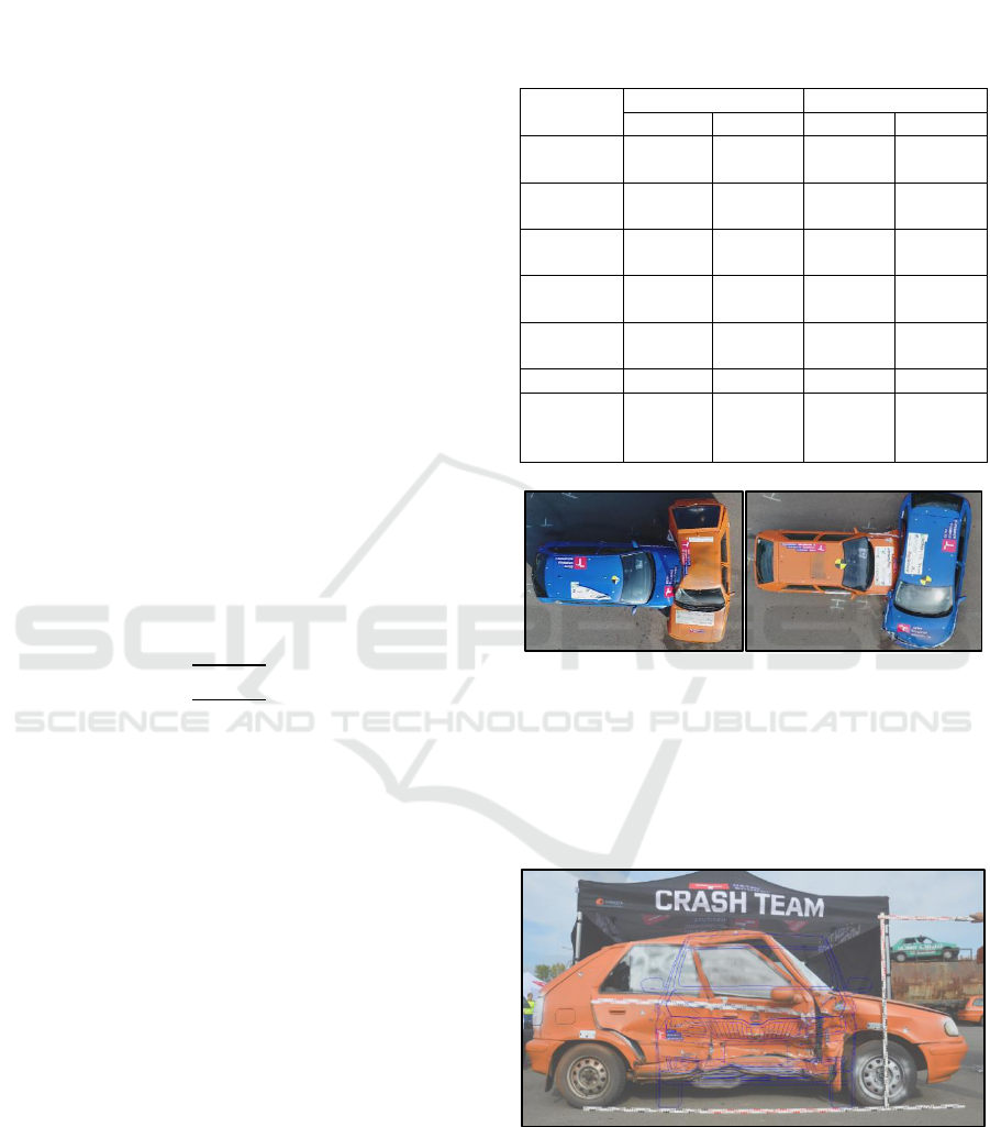
Figure 1: Crash tests configuration.
2.1 Crash Test 1
In the first crash test vehicle Skoda Rapid crashed in
approximately 55 km/h into the side of the vehicle
Skoda Felicia.
Figure 2: Damage correspondence - crash test 1.
Skoda Rapid has significant damage in the area of
the front right corner including right headlight and
fender, front bumper and bonnet. The headlight and
bonnet were damaged due to contact in the area of
vehicle Skoda Felicia A-pillar respectively the front
VEHITS 2021 - 7th International Conference on Vehicle Technology and Intelligent Transport Systems
522

edge of the vehicle front door as the area with higher
stiffness. The Skoda Rapid bumper was horizontally
broken also due to contact with the front edge of the
Skoda Felicia front door. On the Skoda Rapid bumper
in the area of the right front corner is the imprint of
the Skoda Felicia tyre.
Figure 3: Vehicle Skoda Rapid after crash test 1.
Skoda Felicia was significantly damaged on the
right side of the vehicle. Due to the vehicle age and
related extensive corrosion of the load-bearing parts
of vehicle bodywork, the vehicle bodywork collapsed
(evident from the damage of the vehicle sill and
vehicle floor in the area of the front passenger seat
and vehicle roof braking), front door breakage and
damage of the front door under A-pillar caused by
front bumper reinforcement of the vehicle Rapid.
The entire area of Felicia's B-pillar intruded into
the vehicle interior. The vehicle components
collapsed and the occupant survival space was
impaired (vehicle model has almost no deformation
zones). On the right side of the vehicle Felicia is a
clear imprint of the vehicle Rapid mask, bonnet edge,
and front bumper reinforcement.
Figure 4: Vehicle Skoda Felicia after crash test 1.
The impact force was also transferred to the
vehicle's left side – the front fender and door
displacement.
Figure 5: Vehicle Skoda Felicia after crash test 1.
2.2 Crash Test 2
In the second crash test vehicle Skoda Felicia crashed
at approximately 57 km/h into the side of the vehicle
Skoda Rapid.
Figure 6: Vehicle Skoda Rapid after crash test 2.
Figure 7: Vehicle Skoda Felicia after crash test 2.
Let It Crash! Energy Equivalent Speed Determination
523

The whole front part of the vehicle Skoda Felicia
was damaged –both fenders, front bumper and mask,
broken bonnet. Slightly left from the vehicle emblem
on the bonnet, mask and bumper is a clear imprint of
the vehicle Rapid B-pillar.
On the vehicle Skoda Rapid is damaged the right
side in the area of both vehicle doors. The sill and
both doors were damaged. There is no significant
deformation of the B-pillar and the occupant survival
space was not significantly impaired.
2.3 Comparison of the Crash Tests
The Skoda Felicia vehicle damage is significantly
extended in comparison with the modern vehicle
Skoda Rapid. The vehicle obsolescence is manifested
in the vehicle's active and passive safety and also in
the construction itself and used materials. The vehicle
age has also a negative effect on the properties of
some elements. With age increase, the probability of
corrosion is higher, which reduces the rigidity and
leads to the more extensive deformation of vehicle
exterior and interior. The vehicle age increase is also
related to the higher probability of serious injuries
during a traffic crash.
Table 2: The comparison of vehicle damage.
The vehicle front
Skoda Rapid
Skoda Felicia
Slight damage on the right
front corner including the
bonnet, right headlight, and
fender, broken front bumper
Flat deformation of vehicle
front including the broken
bonnet, both fenders, front
bumper, damaged mask
The vehicle side
Skoda Felicia
Skoda Rapid
Extensive corrosion of the
load-bearing parts of vehicle
bodywork
Vehicle bodywork collapsed
Damage of the sill and
vehicle floor in the area of
the front passenger seat,
deformation of the vehicle
roof, deformation of the
B-pillar, and impairment of
the occupant survival space
damaged sill and both right
doors
no significant deformation
of the B-pillar, and
impairment of the occupant
survival space.
3 EES DETERMINATION USING
SELECTED METHODS
For the quantification of the EES parameter was used
comparison method and PC-Crash CRASH 3 module.
PC-Crash is one of the most widely used programs for
collision reconstruction worldwide (Richardson et al.,
2015) The obtained results were compared with the
EES determined using data from crash tests.
3.1 Crash Tests
The crash parts could be divided into following
stages: (Coufal, 2014, Daily at al., 2006):
• Collision – two objects interactions with large
forces over a short time.
• Compression – the kinetic energy is absorbed and
the object is deformed. The compression phase is
terminated when a dynamic deformation reaches
a maximum.
• Restitution – during the rebound phase is some
stored energy turned back into kinetic energy and
the object departs with some relative speed.
For the determination of vehicle deformation during
crash tests were considered these individual parts of a
crash and quantified corresponding energy in these
individual crash parts - the plastic deformation
energy, the elastic deformation energy, and also the
maximum of deformation energy which corresponds
with the sum of elastic and plastic deformation
energy. The maximum deformation depth at the end
of compression was measured using a top-view photo
from drones.
3.2 Comparison Method
For the EES determination of the damaged vehicle is
necessary to find comparably damaged vehicles with
known EES in the EES catalogue. The Skoda Felicia
front deformation was compared e.g. with the vehicle
Skoda Favorit and Suzuki Swift (Figure 7 and Table
3).
Figure 8: Comparison method.
Table 3: The example of the comparison method.
m
c
[kg]
EES
c
[km/h]
m
v
[kg]
EES
v
[km/h]
Skoda
Favorit
870
29
931
28,0
Suzuki
Swift
775
29
931
26,5
VEHITS 2021 - 7th International Conference on Vehicle Technology and Intelligent Transport Systems
524
3.3 PC-Crash (CRASH 3)
PC–Crash programme CRASH 3 use NHTSA vehicle
databank, where the comparable vehicle needs to be
found for the EES calculation. In the deformation
section is necessary to set the measured permanent
deformation depth in the constant distance with the
maximum 12 sections c
1
to c
n
; k-factor and direction
of the action force. The weight of the analysed vehicle
must be considered, also the impact speed,
deformation depth, and maximum speed in which
deformation does not occur (b
0
) need to be
comparable (Semela, 2012, Brach, 2012). For the
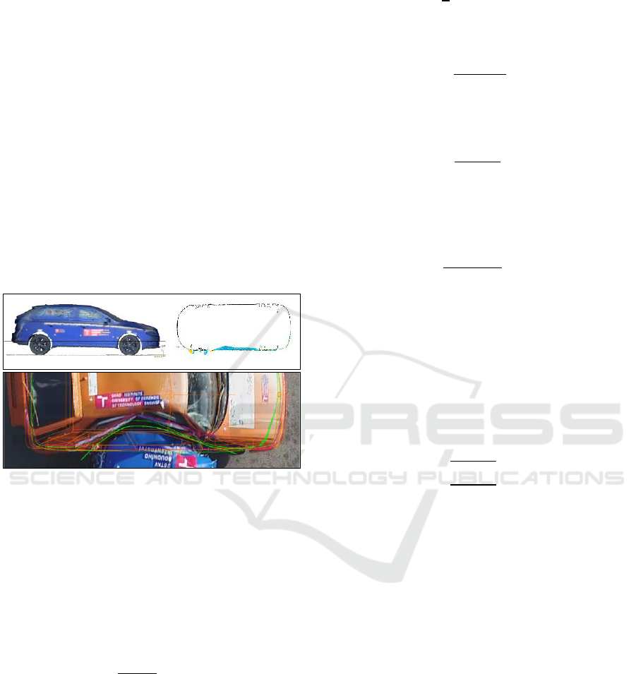
deformation depth measurement were used data from
3D scanner and also top-view photography from
drones. The deformation depth using 3D scan was
averaged from 3 sections in the area of maximum
deformation depth.
Figure 9: The measurement of deformation depth using 3D
scanner.
Software PC–Crash programme CRASH 3
considers one central stiffness characteristic of the
whole vehicle front. EES (respectively deformation
energy) of the front damaged vehicle was used for the
determination of the vehicle side damaged vehicle.
For both vehicles is calculated maximum deformation
depth X using the average plastic deformation depth
X
p
and elastic deformation depth X
e
.
(2)
(3)
For the determination of maximum impact force F
max
is used the quantified maximum deformation energy
E
D1
of the front damaged vehicle:
,
(4)
where E
DP
is the plastic deformation energy of
vehicle 1:
(5)
And E
DE1
is elastic deformation energy of vehicle 1:
(6)
The maximum Impact Force F
max
could be then
determined as:
(7)
The maximum impact force is equal for both vehicles
and could be used for the determination of maximum
deformation energy E
D2
of vehicle two:
(8)
The elastic deformation energy of vehicle 2 could be
then determined as:
(9)
and the plastic deformation energy of vehicle 2 as:
(10)
EES of the side damaged vehicle is determined using
equation:
(11)
4 RESULTS: EES
EES parameter was determined using the comparison
method (EES catalogue) and PC-Crash CRASH 3
module. For EES determination in PC–Crash
CRASH 3 module is necessary to determine the
deformation depth. Two methods of deformation
depth measurement were used – measurement from
top-view photography and 3D scans. For the
measurement of deformation depth from 3D scans
were averaged values from three sections (cuts) in the
area of maximum deformation. The EES of the
vehicle side damaged were determined based on the
EES of the crash opponent.
The obtained EES values were compared with the
EES determined using data from crash tests. Table 2
illustrates the obtained EES results in relation to the
used method. Table 4 illustrates calculated EES using
selected methods (comparison methods, a calculation
based on the crash test data, PC-Crash, and
Let It Crash! Energy Equivalent Speed Determination
525

deformation depth obtained from top-view
photography and 3D scanner). The procedure of EES
determination using these methods was described in
the previous chapter.
Table 4: Determined EES using selected methods.
Crash
Comparison
method
[km/h]
PC-crash
Crash
test
[km/h]
Top-view
[km/h]
Scanner
[km/h]
1
Rapid
18-22
14 - 16
14 - 17
13 - 16
Felicia
26-30
30 - 37
32 - 39
23 - 28
2
Felicia
24-29
28 - 34
31 - 38
25 - 32
Rapid
19-24
12 - 14
16 - 19
10 - 15
Besides the comparative method, there are
significant deviations of determined EES only in the
case of the side-damaged Skoda Felicia vehicle. This
deviation can be caused by the extent vehicle
corrosion, inappropriate selection of stiffness in the
PC-Crash software, or distortion of deformation
depth measurements. The results can be also
influenced by the set speed value b
0
.
Resulting EES from the comparison methods is
comparable with data obtained from crash tests for
the Skoda Felicia vehicle. Usability of the
comparison method for the vehicle Skoda Rapid is
limited because the used EES catalogue (Melegh,
2005) contains mostly older vehicle models.
5 DISCUSSION
This article aimed to introduce the results of two crash
tests representing the comparison of the stiffness and
technological obsolescence. On these crash tests were
analysed limits of the selected methods for EES
determination. The EES value expresses the kinetic
energy dissipated by the vehicle during the contact
phase i.e energy converted to thermal energy through
deformation (Berg, 1998).
Structural behavior and properties differ
depending e.g. on the vehicle model. Even similar
vehicles (similar weight/length/width) could have
different deformation characteristics, especially
depending on the vehicle stiffness influenced by the
degradation of vehicle bodywork (Abellán-López,
2018; Vangi, 2020).
Realised crash tests of comparable vehicles in
similar impact speed only inverted collision scenario
(first crash scenario – modern vehicle Skoda Rapid
crashed into the side of old vehicle Skoda Felicia,
second crash scenario – old vehicle Skoda Felicia
crashed into the side of the Skoda Rapid) demonstrate
the influence of the vehicle age (and related
degradation – corrosion of the bodywork),
respectively technological obsolescence (and the
related difference in the stiffness) to the resulting
extent of the damage. Deformation of Skoda Felicia
is significantly more extensive in comparison with the
modern vehicle Skoda Rapid. During side impact into
the vehicle Skoda Felicia was impaired the occupant
survival space.
The EES were determined for all tested vehicles
using selected methods - based on the crash test
results, using PC–Crash CRASH 3 module and
comparison method. The deformation depth was
measured using a top view photo from a drone and 3D
scans.
The calculated EES values for the frontal damage
of vehicle Skoda Felicia are comparable. Used EES
catalogue (Melegh, 2005) contains mostly older
vehicle models. Used database in the module
CRASH 3 in PC-Crash software is applicable
primarily on the frontal damage. Top-view
photography use for the frontal deformation depth
measurement is mostly not affected by significant
deviation, because the damage is mostly not covered
by other vehicle parts – as vehicle hood (which could
be a limitation of the top-view photography usage for
deformation depth measurement of the vehicle side
deformation).
The EES values determined using comparison
with the damage of vehicle with known EES value
could be inaccurate for the modern vehicles, as
proved by EES values of Skoda Rapid vehicle. The
EES catalogues mostly do not contain modern
vehicles. The limitation is also the subjectivity of the
extent of vehicle damage assessment during the
determination of similarly damaged vehicles for
comparison.
Determination of the EES using module
CRASH 3 in the PC-Crash software is influenced by
accessible vehicle and their stiffness. The users have
to select a vehicle from the NHTSA databank, US
vehicles could have different stiffness in comparison
with vehicles in the European market (Macurová,
2019). Coufal (2014) compared EES calculation
using correlation diagram, comparison method and
CRASH 3. As one of the main limitations author
concluded that the different stiffness of individual
vehicle parts is not considered, as these methods
assume homogeneous rigidity for the front of the
vehicle.
Results can be also influenced by the inaccuracy
of the deformation depth measurement
(Żuchowski, 2015). Deformation depth measurement
using a top-view photo is limited especially during
vehicle side deformation, where could be the
maximum deformation depth covered by vehicle roof
or other vehicle parts (Moravcová, 2019). Usability
VEHITS 2021 - 7th International Conference on Vehicle Technology and Intelligent Transport Systems
526

of the 3D scanner could be also limited, it is not
possible to document plastic deformation - coverage
of deformation by another vehicle part or detachment
of vehicle body part as a result of the collision. For
elimination of results, distortion could be in some
specific cases most appropriate combine several
measurement methods. Papić et al. (2017) emphasize
the usability of a 3D model (which allows to analyse
of deformation depth in individual sections) in
combination with crash reconstruction software.
As evidenced by obtained results, the EES
parameter could be determined in a relatively wide
range. Quantified deformation energy is one of the
basic parameters for the crash analysis. Significant
inaccuracy in the EES determination could influence
determined impact speed. The methods for crash
documentation and subsequent analysis need to be
used concerning the collision type, deformation
character and extent, and vehicle characteristics.
Future research activities will be focused on the
analysis of efficiency, usability and accuracy of
various methods for documentation and vehicle
deformation quantification. Selected methods will be
experimentally verified during crash tests and real
traffic crashes documentation and their subsequent
analysis.
6 CONCLUSIONS
Crash analysis including determination of the impact
speed is one of the main assumptions for the
clarification of mostly negligent crimes. For crash
reconstruction, various simulation models can be
used. During crash reconstruction is necessary to
considered specifics and limitations of used methods,
thus different methods should be used depending on
the collision types and specific condition (Hoxha,
2017). The inaccuracy of the input affects the output,
to achieve more credible output is necessary to used
sophisticated and precise methods which allow to
document values corresponding with the real
situation Svatý (2020). Precise documentation of
crashes (especially brake traces) is crucial for the
subsequent crash analysis.
The impact speed determination could be based
not only on the crash reconstruction but also obtained
from vehicle cameras or Event Data recorders (EDR).
Previous studies prove the necessity to verify
obtained values. The results distortion could occur
e.g. due to significant deformation, the control unit
damage, recording algorithm delay, or insufficient
recording memory or vehicle skidding
(Gwehenberger, 2020). The usability of EDR is
currently limited in the EU due to legislation.
Therefore, it is still necessary to improve methods for
crash documentation and analysis (including EES
determination).
The parameters which could serve as a basis for
the crash analysis (such as vehicle stiffness) could be
obtained from the vehicle crash tests (Dima, 2019).
Crash tests are realized by many organizations mostly
to ensure vehicle safe design e.g. Insurance Institute
for Highway Safety (IIHS), National Highway Traffic
Safety Administration (NHTSA), DEKRA, Transport
Research Laboratory (TRL), Dynamic Test Center
(DTC), Crashtest-service (CTS), etc. The usability of
data from commercial crash tests focused on vehicle
safety testing or homologation is limited for forensic
engineering purposes. Crash tests are mainly realised
with the new vehicles that are not affected by material
degradation. A number of studies pointed to the
differences in the deformation behaviour in relation
to the vehicle age or obsolescence. There are also
differences in brands or vehicle models (Kullgren,
2010, Görtz, 2018; Covaciu, 2016). For the crash
analysis in the forensic engineering is necessary to
conducted not only crash tests of new vehicles, but
also of older vehicles, which may have different
characteristics. For these purposes also data
collection from real traffic crashes and the subsequent
validation of the calculated data within crash tests
could be beneficial. Experimentally obtained data
enable improvement and refinement of input values
for simulation modelling and crash calculation.
ACKNOWLEDGEMENTS
The article was produced with the financial support
of the Ministry of Transport within the programme of
the long-term conceptual development of research
institutions on the research infrastructure acquired
from the Operation Programme Research and
Development for Innovations
(CZ.1.05/2.1.00/03.0064) and within the project of
specific research ÚSI-J-20-6378.
REFERENCES
Abellán-lópez, D., Sánchez-lozano, M., & Martínez-sáez,
L. (2018). Frontal crashworthiness characterisation of
a vehicle segment using curve comparison metrics.
Crash Analysis & Prevention, 117, 136–144.
Berg, F. A., Walz, F., Bürkle, H., & Epple, J. (1998).
Implications of velocity change delta-v and energy
equivalent speed ees for injury mechanism assessment
Let It Crash! Energy Equivalent Speed Determination
527

in various collision configura tions. In Proc. IRCOBI
Conf. on Biomechanics, Göteborg.
Bradáč, A. a kol. Soudní inženýrství. 1. vydání. Brno:
Akademické nakladatelství CERM s.r.o., 1999. 725 s.
ISBN 80-7204-133-9.
Brach, R. M., Brach, R. M., & Louderback, A.
(2012). Uncertainty of CRASH3 ΔV and Energy Loss
for Frontal Collisions. SAE Technical Paper Series.
doi:10.4271/2012-01-0608.
Burg, H., & Moser, A. (Eds.). (2017). Handbuch
Verkehrsunfallrekonstruktion.
Čopiak, M. 2019. Špecifiká problematiky energeticky
ekvivalentnej rýchlosti pri analýze nehodového deja:
Projekt k dizertačnej práci. Žilina: UZVV UNIZA,
2019.
Čopiak, M., Korbeľ, T. a Imrich, L. Princíp určenia
energeticky ekvivalentnej rýchlosti s využitím programu
pc-crash. Trilobit [online]. 2019(1).
Coufal, T. Analýza tuhosti přední části vozidel. Brno:
Vysoké učení technické v Brně, Ústav soudního
inženýrství, 2014.
Covaciu, D., & Dima, D. S. (2016). Crash Tests Data
Acquisition and Processing. CONAT 2016
International Congress of Automotive and Transport
Engineering, 782–789.
Daily, Jeremy, Russell Strickland a John Daily Crush
Analysis with Under-rides and the Coefficient of
Restitution: Institute of Police Technology and
Management’s. 2006, 1-77.
Dima, D. S., & Covaciu, D. (2019). Vehicles Frontal
Impact Analysis Using Computer Simulation and Crash
Test. International Journal of Automotive Technology,
20(4), 655–661. doi:10.1007/s12239-019-0062-3.
Görtz, M. 2018. Model určovania deformačných energií na
vozidlách po dopravných nehodách: Dizertačná práca.
Žilina: UZVV UNIZA, 2018.
Gwehenberger, J., Braxmeier, O., Lauterwasser, Ch.,
Kreutner, M., Borrack M., and Reinkemeyer, C. Needs
and Requirements of EDR for Automated Vehicles -
Analysis Based on Insurance Claims Reported to
Allianz Germany. 2020.
Hoxha, G., Shala, A., Likaj, R. (2017). Vehicle Speed
Determination in Case of Road Crash by Software
Method and Comparing of Results with the
Mathematical Model. Journal of Mechanical
Engineering, 67(2), 51–60.
Kullgren A., Anders Lie & Claes Tingvall (2010)
Comparison Between Euro NCAP Test Results and
Real-World Crash Data, Traffic Injury Prevention,
11:6, 587-593,
Macurová L., Kohút, P, Čopiak, M, Imrich L., Rédl, M.
Determinig the Energy Equivalent Speed by Using
Software Based on the Finite Element Method,
Transportation Research Procedia, Volume 44,
2020,Pages 219-225,ISSN 2352-1465.
Melegh, G. CD-EES 4.0 [CD-R]. Hungary: AutoExpert
Hungary, 2005.
Moravcová, P.; Bucsuházy, K.; Zůvala, R.; Bilík, M. and
Bradáč, A. (2020). The Comparison of 3D and 2D
Measurement Techniques Used for the Analysis of
Vehicle Deformation. In Proceedings of the 6th
International Conference on Vehicle Technology and
Intelligent Transport Systems - Volume 1:
VEHITS, ISBN 978-989-758-419-0, pages 195-202.
Papić, Z., Bogdanović, V., Štetin, G., Saulic, N. (2018).
Estimation of ees values by vehicle 3-d modelling.
Mobility and Vehicle Mechanics. 44. 29-41.
10.24874/mvm.2018.44.01.03.
Richardson, S., Moser, A., Orton, T. L., & Zou, R. (2015).
Simulation of vehicle lateral side impacts with poles to
estimate crush and impact speed characteristics (No.
2015-01-1428). SAE Technical Paper.
Semela, M. Analýza silničních nehod I. 1. vydání ÚSI VUT
v Brně, 2012. ISBN 978-80-214-4559-8.
Semela, M. Analýza silničních nehod II, Ústav soudního
inženýrství, VUT v Brně. 2014.
Svatý, Z., Mičunek, T a Nováček J. ExFoS 2020: Využití
prostorových dat pro účely simulace nehodového děje.
2020. ISBN 978-80-214-5829-1.
Sztwiertnia K, Guzek M. Uncertainty of determining the e
nergy equivalent speed (EES) of a vehicle collision by
the experimental and analytical method.
The Archives of Automotive Engineering – Archiwum
Motoryzacji. 2017; 76(2): 123-136,
Vangi D., Vehicle Collision Dynamics, Butterworth-
Heinemann, 2020, Page xv, ISBN 9780128127506,
https://doi.org/10.1016/B978-0-12-812750-6.00013-5.
Vangi, D., Begani, F. The Triangle Method for Evaluation.
In 19th EVU Congress. Brno: Tribun EU s.r.o., 2010. s.
265-299. ISBN 978-80-7399-128-9.
Vangi, D., Cialdai C. and GULINO, M. Vehicle stiffness
assessment for energy loss evaluation in vehicle
impacts. Forensic science international. Elsevier B.V,
2019, 300, 136-144. ISSN 0379-0738.
Vangi, Dario. Simplified method for evaluating energy loss
in vehicle collisions. Crash analysis and
prevention [online]. Elsevier, 2009, 41(3), 633-641 [cit.
2020-11-27]. ISSN 0001-4575.
Żuchowski A. The use of energy methods at the calculation
of vehicle impact velocity. The Archives of Automotive
Engineering – Archiwum Motoryzacji. 2015;68(2):85-
111.
VEHITS 2021 - 7th International Conference on Vehicle Technology and Intelligent Transport Systems
528
