
Synchronous and Asynchronous Requirements for Digital Twins
Applications in Industry 4.0
Rafael F. Vitor
1 a
, Breno N. S. Keller
1 b
, D
´
ebora L. M. Barbosa
1 c
, D
´
ebora N. Diniz
1 d
,
Mateus C. Silva
1,2 e
, Ricardo A. R. Oliveira
1 f
and Saul E. Delabrida S.
1 g
1
Departamento de Computac¸
˜
ao, Instituto de Ci
ˆ
encias Exatas e Biol
´
ogicas, Universidade Federal de Ouro Preto, Brazil
2
Instituto Federal de Educac¸
˜
ao, Ci
ˆ
encia e Tecnologia de Minas Gerais, Campus Avanc¸ado Itabirito, Brazil
Keywords:
Industry 4.0, IIoT, Digital Twins, Virtualization, Real-Time Constraints, DES Simulation.
Abstract:
The Industry 4.0 revolution brings up novel concepts and restraints when proposing and designing novel ap-
plications. Although its perspectives are new, the main restraints must also observe conservative constraints of
the industrial processes, such as real-time capability and asynchronous design. Among the main tools to de-
velop cutting-edge industrial applications, a novel relevant approach to presenting information and interacting
with the Digital Twins (DTs) process. This work evaluates how to model and measure the primary Industry 4.0
constraints in designing novel applications using DTs. This work separates the restraints into two categories:
asynchronous and synchronous requirements. First, this work designs a high-level DT system communication
flow through a Petri Net model to analyze the asynchronous requirements. Then, it performs a synchronous
test with a physical instance of the proposed model. The results display the requirements for safe operation on
the case-study system regarding timing and modeling constraints.
1 INTRODUCTION
Besides the third industrial revolution that aimed at
automating processes and reduce human labor, one of
the main objectives of Industry 4.0 is placing oper-
ators and machines to work in cooperation (Bilberg
and Hadar, 2012; Kolberg and Z
¨
uhlke, 2015). In this
way, machines contributing to their strength and pre-
cision to exhaustive tasks, whereas humans are re-
sponsible for the decision-making process (Doltsinis
et al., 2017; Romero et al., 2016). To support this
objective, Industry 4.0 modifies the production chain
with novel approaches like Cyber-Physical Systems
(CPS) (Vogel-Heuser and Hess, 2016) and Internet of
Things (IoT) (Atzori et al., 2010). Some of the fun-
damental concepts in designing Industry 4.0 applica-
tions are: (i) Interoperability, (ii) Virtualization, (iii)
a
https://orcid.org/0000-0001-6904-8414
b
https://orcid.org/0000-0001-5414-6716
c
https://orcid.org/0000-0002-8119-4964
d
https://orcid.org/0000-0002-1951-8868
e
https://orcid.org/0000-0003-3717-1906
f
https://orcid.org/0000-0001-5167-1523
g
https://orcid.org/0000-0002-8961-5313
Real-Time Capability, and (iv) Modularity (Saldivar
et al., 2015).
An essential tool to create these systems in the in-
dustrial context is virtualization. It is often performed
through digital representations of the machines and
devices, known as Digital Twins (DTs) (Schluse et al.,
2018).
A DT is a system composed of a physical object
and its virtual counterpart. The virtual representation
is developed to be a functional replica of its counter-
part in the real world, relying on received operational
data (Boschert et al., 2018). This replica aims to in-
terfere with operators and machines, provide relevant
information from the equipment, and receive act com-
mands. The system should be capable of monitoring
and reflecting on the behavior of the physical object.
With the storing of this operational data, it is also pos-
sible to apply AI and make predictions on that equip-
ment’s behavior (Gabor et al., 2016).
In distributed systems, the real-time requirements
are directly related to the networking capability for
data transfer. It represents the synchronous require-
ments for network-based systems. Thus, it is possi-
ble to evaluate those systems by Quality-of-Service
(QoS) matter (Silva and Oliveira, 2019). In the DT
Vitor, R., Keller, B., Barbosa, D., Diniz, D., Silva, M., Oliveira, R. and S., S.
Synchronous and Asynchronous Requirements for Digital Twins Applications in Industry 4.0.
DOI: 10.5220/0010444406370647
In Proceedings of the 23rd International Conference on Enterprise Information Systems (ICEIS 2021) - Volume 2, pages 637-647
ISBN: 978-989-758-509-8
Copyright
c
2021 by SCITEPRESS – Science and Technology Publications, Lda. All rights reserved
637
aspect, the synchronous requirements represent the
DT parts’ dataflow: physical object, a virtual entity,
and human-machine interface (HMI). Efficient infor-
mation exchange supports DT reliability.
Many wireless technologies, such as 4G, 5G, or
even 6G, have been discussed to support latency-
sensitive services that require extreme reliability. 4G
was developed to solve IT computing problems in the
cloud. Its vision and tech standards emerged in 2000
until reaching a deployment maturity in 2012. Thus,
in 2012, vision and tech standards for 5G emerged.
5G would bring significant advances to low latency,
reaching a peak of 20 Gbps. By 2020, there is a
growing interest in bringing computing power closer
to mobile devices with its commercial deployment.
However, some analyses indicate that the 5G transfer
rate is still insufficient for a genuinely immersive DT
technologies experience. Therefore, in 2020, plans
for 6G started with a perspective that by 2028 its de-
ployment could improve rates close to 1,000 Gbps.
In a 6G environment, through DTs, users can ex-
plore and monitor reality in the virtual world, without
temporal or spatial restrictions (Samsung Research,
2020).
In contrast, industrial processes often work based
on asynchronous events, such as requests and de-
cisions (Almassalkhi et al., 2017). The system
must model event-based asynchronous methods with-
out disrespecting the previously established real-time
constraints. The system designers may also want to
integrate new modules into previously existing sys-
tems. As modularity is a trait from IoT and Indus-
try 4.0, this process must incorporate it into the asyn-
chronous model without compromising the real-time
restraints. For this matter, the model must be easy to
update and verify.
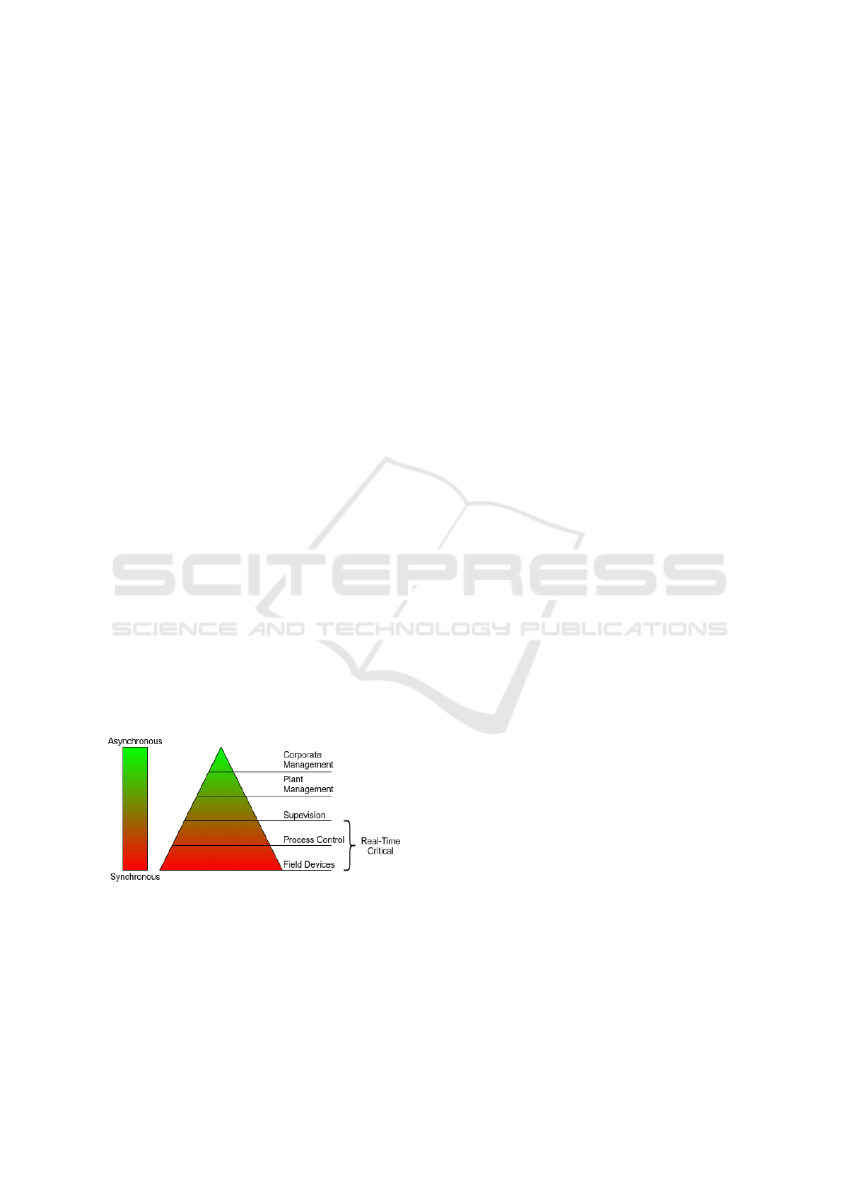
Figure 1: IPAS Hierarchy and Synchronicity Requirements.
Using the Industrial Process Automation System
(IPAS) hierarchy, it is possible to analyze how each
part of the industrial processes relates to synchronous
and asynchronous requirements (Garrocho et al.,
2019). Figure 1 displays this representation. While
the process control and field device management
mainly require synchronous aspects, the corporate
and plant management present mostly asynchronous
aspects. In the very middle, the supervision combines
both aspects, and it is where the context presented for
the DT applies.
Thus the objective of this work is:
• Analyze the DT synchronous requirements in a
high-level model and its asynchronous issues over
an architecture instance.
The outline of the paper is as follows. Section 2 ex-
poses the main concepts and related works of this
study. Section 3 shows the case study used to dis-
cuss the proposal. Section 4 presents the experimen-
tal results obtained from the case study. Finally, the
conclusions are presented in Section 5.
2 THEORETICAL REFERENCES
This section provides theoretical study work that an-
alyzes the state-of-the-art and most recent works re-
lated to Industry 4.0, IoT, DT, and discrete events sys-
tems (DES) simulation using Petri Nets (PNs).
2.1 Industry 4.0 and the Internet of
Things
Industry 4.0 is the latest technological revolution in
the industrial environment (Lasi et al., 2014). Among
its main topics there are decentralization, flexibility,
and resource efficiency.
The revolution bases its concept on industrial
plant digitalization and the integration of its elements,
powered by the IoT (Atzori et al., 2010). There
are increasing devices connected to networks capa-
ble of producing, processing, and exchanging infor-
mation among human and industrial plant compo-
nents (Taneja and Davy, 2017). This perspective
enforces a pervasive and ubiquitous distributed de-
vice network. Naturally, IoT applications have syn-
chronous issues, which become network constraints
(Samie et al., 2016).
IoT constraints are more strict in an industrial en-
vironment as the system reliability involves human
security and industrial plant integrity. Thus, it en-
forces the importance of the synchronous require-
ments evaluation based on network QoS issues (Silva
and Oliveira, 2019). Considering this environment,
IoT is named as the Industrial Internet of Things
(IIoT) (Sisinni et al., 2018).
One way to analyze the IIoT system is to divide its
components into five layers: sensors/actuators, net-
work, integration, augmented intelligence, and aug-
ICEIS 2021 - 23rd International Conference on Enterprise Information Systems
638

mented behavior (Holdowsky et al., 2015). In the first
layer, the sensors are responsible for extracting raw
data from the machine. Also, it receives commands
and interprets them to trigger the actuators and change
the machine state.
The network layer allows data traffic among IIoT
parts. Then, the integration layer manages data from
different sources and group them to be analyzed.
The augmented intelligence layer performs opera-
tions, as AI techniques, into the data to extract knowl-
edge. Among a diversified number of AI techniques,
machine-learning algorithms often are used to solve
this sort of problem. However, with the increasing
data, new techniques as Big Data emerges as an al-
ternative to handle a large number of data (Qi and
Tao, 2018). Lastly, the augmented behavior layer is
responsible for reporting the knowledge obtained or
acting in the object of study.
An industrial scenario example is the IIoT in the
mining industry (Amorim et al., 2019). Mine safety is
a big challenge due to working conditions. To prevent
accidents, wireless communications solutions (RFID,
Wi-Fi) can transfer data from the IIoT to monitoring
sensors that allow a supervisor to understand better
the mining plant’s real scenario and conditions (such
as equipment and machines). However, those IIoT
devices have constraints as energy dependency. To
supply its needs, it could add risk to the plant (e.g.,
one of the conductors could break up and detonate
gas in the mine) (Da Xu et al., 2014).
2.2 Digital Twin
DTs are systems that aim to display physical objects’
characteristics and behavior in the virtual environ-
ment (Schluse et al., 2018). They can describe the
current state of a physical object, monitor and pro-
vide analysis, recommendations, and predictions to
the user about the functioning of a specific physical
object state (Gabor et al., 2016; Rosen et al., 2015).
This technology targets improving the inspection,
monitoring, and maintenance of objects (equipment
and machines). Also, this system allows that pos-
sible decision-making is verified before sending the
command of action. The main objective is reduc-
ing the time and effort on maintenance inspections
in the industrial scenario, simplifying and making the
decision-making process safer for the operator.
Figure 2 shows an example of DT main compo-
nents: a physical object (PO), a virtual entity (VE),
and a human-machine interface (HMI). To compre-
hend the DT dataflow, it is necessary to understand
the relationship between its parts, represented as di-
rectional arrows, and explained as follows.
PO. The physical object, first, equipped with IIoT
sensors, can send its sensed data to the virtual en-
tity through PO/VE. The physical object also has
IIoT actuators that can trigger commands coming
from VE/PO.
VE. The virtual entity may receive data from PO
through PO/VE or HMI through HMI/VE. Com-
ing from PO, the virtual entity uses the informa-
tion to feed AI algorithms capable of improving
its learning and extracting the PO state’s knowl-
edge. It also updates the abstract representation.
On the one hand, Based on the data received from
PO/VE, the virtual entity may carry the informa-
tion on to the HMI (through VE/HMI). In addition
to the physical object state data, this information
may be attached with an alert if the AI realizes that
somethings are relevant to the user’s knowledge.
On the other hand, if the AI detects a problem and
can act itself, it sends an action command to the
physical object through VE/PO. In a second sce-
nario, the information that comes from HMI/VE
holds a command from the user. Thus, the vir-
tual entity validates if the command is safe for the
PO. If positive, it passes the command on through
VE/PO. Otherwise, it emits an alert to the HMI
through VE/HMI.
HMI. The human-machine interface receives data
from the VE through VE/HMI and render its in-
formation in the visual interface. The human-
machine interface also has an input component
that allows a user to send a command through
HMI/VE, where it will be validated.
The main difference between DTs and simulation sys-
tems is in terms of specificity. Simulators are generic
and do not consider the current state of the equipment.
They always present the same response according to
a set of conditions. In contrast, each DT is unique
and linked to its corresponding physical object. Its
ability to keep the information of the object updated
allows DT to adapt its model. For instance, worn-
out equipment may not have the same response as a
brand-new device of the same model. That occurs due
to wear and calibrations that vary with time of opera-
tion and way of use. Therefore, as DT keeps monitor-
ing the equipment by updating its status information,
it is possible to make more reliable predictions.
Often DTs are confused with AI techniques as Big
Data. The main differences between DTs and Big
Data are related to the virtual entity. According to Tao
and Zhang (Tao and Zhang, 2017), the virtual entity
has four levels of abstraction: the geometric repre-
sentation (three-dimensional modeling), the physical
modeling (representation and performance of forces),
Synchronous and Asynchronous Requirements for Digital Twins Applications in Industry 4.0
639
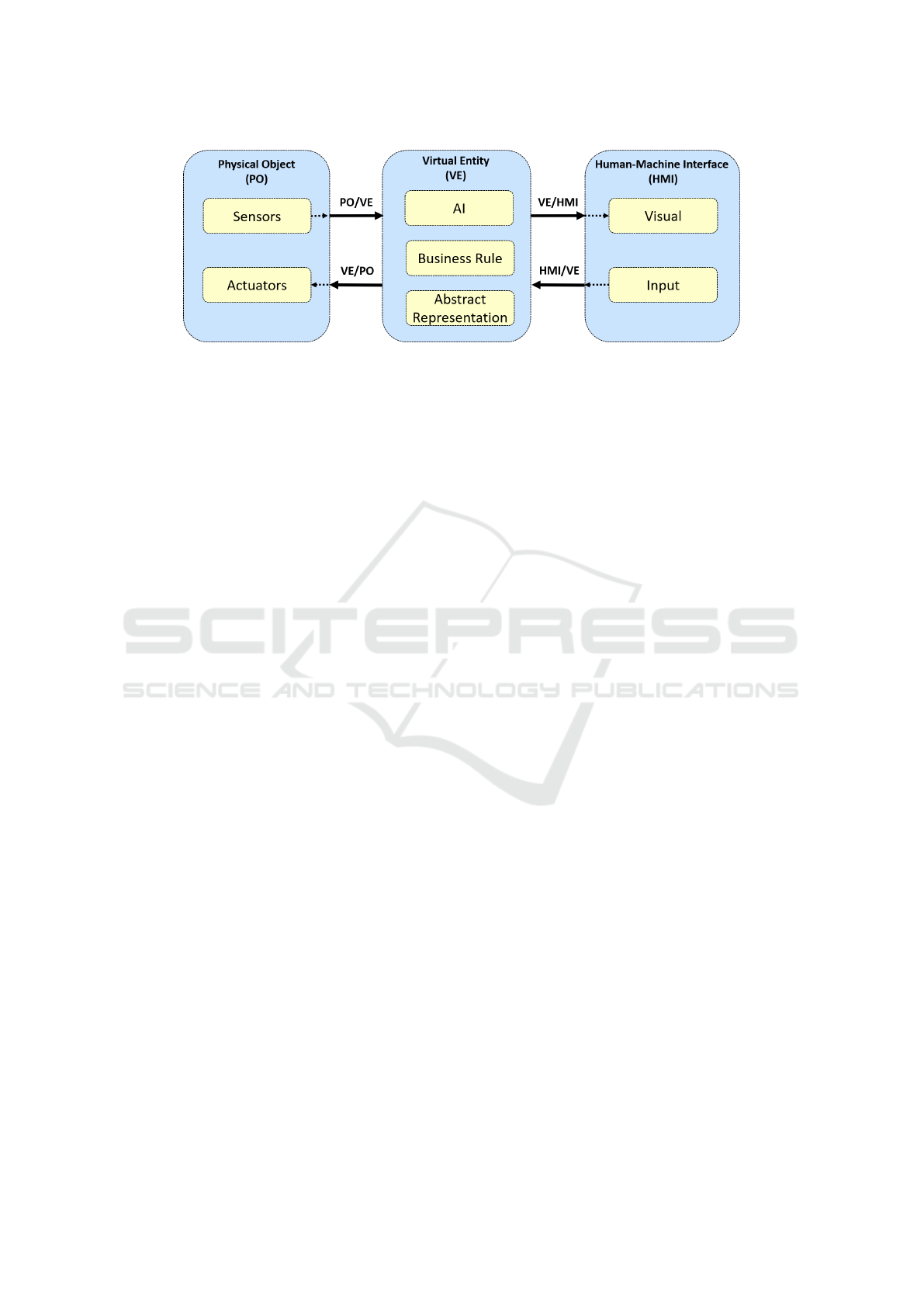
Figure 2: Digital Twin Main Components.
the behavioral structure (response to stimuli as hu-
man activation and interference) and the formulation
of rules (identification and association of patterns of
behavior). Big Data can be part of the DT AI (Qi and
Tao, 2018), improving its intelligence. However, it
does not represent the whole DT.
2.3 DES Simulation using Petri Nets
DES simulation is a powerful feature to ensure the
development of Industry 4.0. The IIoT devices can
group and process information in different locations,
using direct and persistent connections. However,
they also bring new challenges, such as manag-
ing many devices that communicate with each other
(Fortino et al., 2017).
All this communication and information flow re-
quires models that guarantee synchronism, security,
traceability, and time constraints. One way of de-
scribing and modeling a distributed system is using
Petri Nets (PNs). PNs are efficient for modeling, con-
trol, and analysis of Dynamic Discrete Event Systems
(DDES). A basic PN is a bipartite graph directed with
two types of nodes (places and transitions), a marker
element (token), and a directional arc (flow arrows)
(Jezequel et al., 2015).
In the graphical representation, the places are cir-
cles that represent regions of accumulation of tokens.
These tokens are dots inside the place circle and de-
scribe the state-specific values. Transitions are rect-
angles that allow the movement of tokens between
places through arcs. The arcs are represented by di-
rectional arrows that connect the two types of places
and transitions. Each arc has a weight associated, lim-
iting the number of tokens that can move from one
node to another. Firing the transitions starts the PN
execution. The tokens in each place move according
to the arcs weights and transitions rules. After each
PN round, there is a token distribution that represents
a PN state, including the initial state (Zhang et al.,
2015).
Formally, a PN is a 5-tuple PN = (P, T, F, W, M
s
).
P represents a finite set of places P =
{p
0
, p
1
, p
2
, p
3
, ..., p
n
}, while T represents the fi-
nite set of transitions T = {t
0
, t
1
, t
2
, t
3
, ..., t
q
}. F
represents a finite set of arcs that connect nodes P and
T , F ⊆ (P × T) ∪ (T × P). W represents the weights
applied to the arcs (W : F → {1, 2, 3, ...}). It defines
the number of tokens that can move from one arc to
another. M
s
represents the current state of the PN.
Where M
s
= {m
0
, m
1
, m
2
, ..., m
n
} is a set of integers
where each number represents the amount of tokens
relative to their respective places p
i
∈ P. Moreover, s
represents the state number. For each s the movement
of tokens among places determines a different state.
M
0
defines the initial state of the PN (Lomotey et al.,
2017).
Due to PN’s characteristics, it is being used to
model different Industry 4.0 scenarios. To analyze
IoT services through simulation, Yamaguchi et al.
(Yamaguchi et al., 2016) described his IoT service as
an agent-oriented PN. In the same way, Yang et al.
(Yang et al., 2014) ideal his IoT environment as a PN
to optimize its dataflow. Latorre et al. (Latorre-Biel
et al., 2018) proposed a PN model that considered a
token net with the product and a system net to the
facility. The model allowed them to analyze the pro-
duction flow performance and give decision making
support around the system.
Also, Lomotey et al. (Lomotey et al., 2017) used
a PN model to describe IoT health monitoring sys-
tems. According to empirical experiments, they re-
alized that the model guarantees more transparency
of the medical IoT data traceability, high scalability
over peak load conditions, and effectively detect hu-
man fault actions such as spoofing and masking.
3 CASE STUDY
After analyzing the theoretical approaches on this
topic, this work performs a case-study to analyze
ICEIS 2021 - 23rd International Conference on Enterprise Information Systems
640
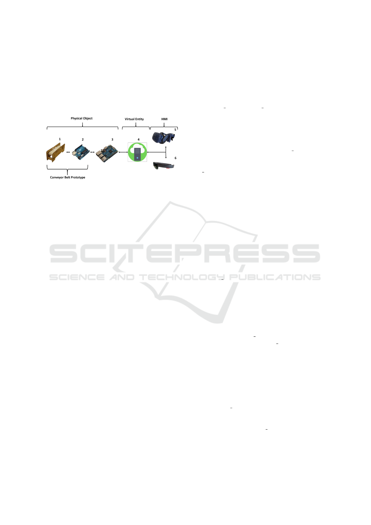
the identified requirements and constraints. Figure 3
presents the implementation of a DT prototype, where
1, 2, 3 are elements corresponding to the physical ob-
ject, 4 represents the virtual entity, and finally, 5 and 6
represent the HMI. The communication among the el-
ements happens through Wi-Fi except between 1 and
2 that have a serial link.
Figure 3: Case Study Prototype Environment Configura-
tion.
Element 1 is a conveyor belt prototype with sensors
and actuators attached to it. It is capable of moni-
toring and controlling its operation. Element 2 is a
microcontroller Arduino that handles the communi-
cation with the sensors and actuators. Elements 1 and
2 combined represent an instance of the conveyor belt
prototype. Each instance communicates with a cen-
tral conveyor handler, represented in 3 by a Raspberry
Pi. It connects the conveyor to the virtual entity, rep-
resented in 4, using Python code and the SocketIO
library.
The virtual entity has an AI component that mon-
itors the conveyor belt’s operation and can act into
it. For example, when detecting an object with an
uncommon size, the AI system can send an alert for-
ward to the HMI or even turn the conveyor belt off for
safety. Python code, Scikit-learn library, and Socke-
tIO were used to implement this element system.
The HTC-VIVE (i.e., VIVE) and Microsoft
Hololens (i.e., Hololens), 5 and 6 represent the HMI,
respectively. They let the user interact with the sys-
tem, receiving feedback from the other parts. It also
allows them to control the conveyors, element 5 in
Virtual Reality and 6 in Augmented Reality.
3.1 Asynchronous Requirement Test
To explain the dataflow through the proposed DT sys-
tem, this work presents a classical PN representa-
tion of the DT architecture in Figure 4. This model
represents a high-level abstraction of the relationship
among DT’s three parts: the physical object, the vir-
tual entity, and the HMI. Also, the PN model explains
the system behavior and its changes. Synchronous re-
quirements as time or connection faults are not repre-
sented in this model, as they are discussed in Section
4.1 with a real instance.
As shown in Figure 4, a token (black dot) repre-
sents the data that flows through the places P. Places
(P) are where the data can be stored or processed:
AI, Business Rule, Abstract Representation, Sensors,
Actuators, Visualization, and Input. Transitions T =
{T
0
, T
1
, T
2
, T
3
, T
4
} are fired when the data token is
ready to proceed to the next places.
It is essential to understand that a token is a tu-
ple of 3 positions: token = (type, payload, message).
type represents the type of data: non actuation or
actuation. According to the type, payload can
contain two different information. When type =
non actuation, payload can contains the sensor data
coming from the physical object. On the other hand,
when it is a actuation, the token payload carries an ac-
tuation command. Finally, message carries additional
information that will complement information to the
human user.
If one of the token information is not relevant to
one place, it ignores that data and passes it on, as it
can be relevant to other places. Each place reach by
the token reacts to the information differently, accord-
ing to its functions. Places may change tokens’ infor-
mation as needed.
Input generates a token with type = actuation,
and the payload contains the sort of command the
user tends to execute. Sensors generates a token with
type = non actuation, and the payload contains the
sensor data from the physical object. Both places do
not add information to message.
When the place AI receives a token, it checks the
type. When type = actuation, it validates if that com-
mand may cause risk. In case that no problem is de-
tected, the place fires the transition sending the to-
ken through. If a possible issue is related, the place
changes the type to non actuation and adds the rea-
son in the message. If type = non actuation, then the
place validate the physical object condition. If no risk
is detected, it adds no risk information to message.
If a warning is detected, the place AI adds a clue to
the message and passes the token through. If a risk is
detected, the place AI change the token type to actua-
tion and substitute payload content with the actuation
command. Besides, it also adds information the mes-
sage relative to its decision.
In Business Rule, the token is validated one more
time and works like the AI place. The difference is
that the AI uses artificial intelligence to validate, and
a human defines the Business Rule.
If the token that reaches Actuators is of type actu-
ation, the place read the actuation command in pay-
Synchronous and Asynchronous Requirements for Digital Twins Applications in Industry 4.0
641
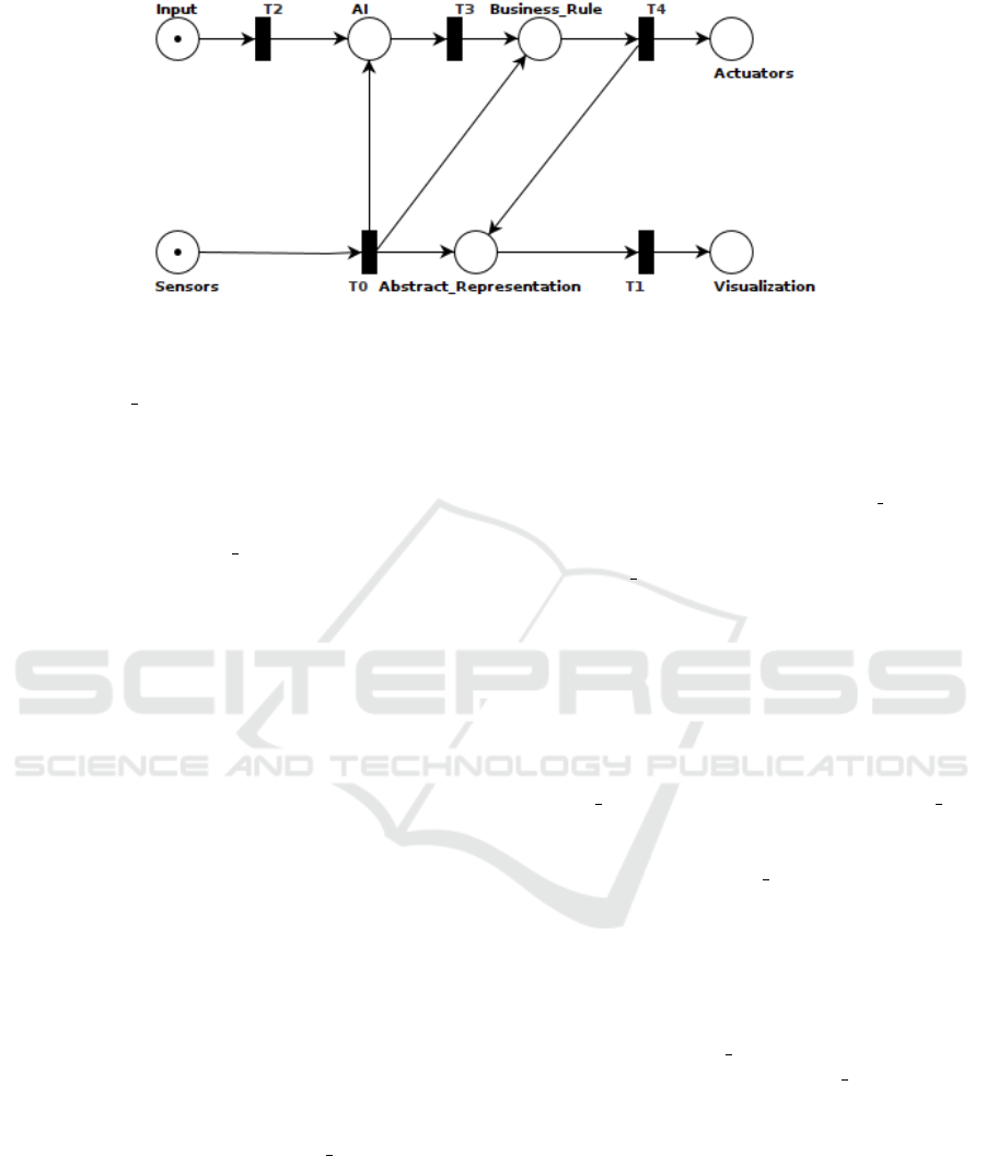
Figure 4: Petri Net Representation of the Proposed System Behavior.
load and process it. Otherwise, it discards the token.
In Abstract Representation, if the token has a mes-
sage, it represents that it has passed in AI. Thus, it
attaches the message to the abstract representation.
However, if it comes with no message, the token
source is the place Sensors. Consequently, it reads the
payload and updates the abstract representation state.
In both, the place Abstract Representation change the
token’s payload and pass it through. The place Visu-
alization receives a token and render its payload and
message to the user.
The initial marking, M
0
, can have a token in the
Input or Sensors. A token in Sensors represents an
IIoT data obtained from the physical object. Whereas
a token in Input, represents a single data input from
the user.
This work proposes dividing the dataflow through
the network into four conditions. They are repre-
sented by arrow pairs in Figure 2. The arrows PO/VE
and VE/HMI represent the Visualization, PO/VE and
VE/PO the Self actuation, VE/HMI and VE/PO the
Human actuation, finally, HMI/VE and VE/HMI the
Input feedback. In case that a transition fires more
the one place, and this place is not referenced in one
of the dataflows explanation, it is because that place
has nothing to do with that token type. Respecting
the classical PN rule, the token is passed, but it is dis-
carded.
Visualization (PO/VE and VE/HMI). The physical
object sends information to the virtual entity that pro-
cesses and passes it to the HMI. Sensors fires T
0
that
pass the data token to the Abstract Representation
that updates its representation state and fires T
1
that delivers that updated representation to the
Visualization.
Self Actuation (PO/VE and VE/PO). Represents the
scenario when a physical object provides information
to the virtual entity that makes a decision without the
need for human intervention and sends the action to
the actuator. Sensors provides data token that fire
T
0
that feed to AI algorithms. If the AI realizes that
an actuation needs to be done and does not need hu-
man decision making expertise, it fires T
3
sending
an actuation type command with an alert message
to the user actuating. In the next place, the token is
checked if it is according to the Business Rule. Then
it fires T
4
, delegating the actuation to the Actuators.
In parallel, the token carries the alert message to
the Abstract Representation that renders the action
alert and fires T
1
delivering the visual alert to the
Visualization.
Human Actuation (VE/HMI and VE/PO). HMI
provides an input action that passes to the virtual
entity that delivers it to the physical object. The
Input provides a actuation type token that fires T
2
and
feeds the AI algorithm that validates the command’s
safety. Then it fires T
3
where the token is filtered by
Business Rule. Then, after the AI and Business Rule
filter, it fires T
4
, delivering the command token to the
Actuator that will act. Also, firing T
4
, a confirmation
token is sent to the Abstract Representation that ren-
ders it and fires T
1
, delivering the command delivery’s
visual confirmation.
Input Feedback (HMI/VE and VE/HMI). HMI pro-
vides an input action that passes to the virtual entity
that processes it and gives feedback to the HMI. Input
provides a data token that feeds the AI algorithm that
fires T
2
where Business Rule will validate the token.
It fires T
4
, passing to the Abstract Representation
that renders it and fires T
1
to deliver the visual infor-
mation.
As this work represented the PN using a classi-
cal approach, its first significant feature is determin-
ism. This property means that from a given PN =
(P, T, F, W, M
s
) state (s), it is possible to determine
whichever the following state. To verify this prop-
erty, the necessary condition is that each place p ∈ P
fires only one transition t ∈ T . As Figure 4 displays,
each place only has one output arc, from which we
conclude that this condition was verified in the mod-
ICEIS 2021 - 23rd International Conference on Enterprise Information Systems
642

eling.
Another critical condition in the analysis of PN
models is the boundness. A PN is considered k-
bounded if, at each possible state of the PN (M
s
),
(m ≤ k, ∀m ∈ M
s
). In expansion, a PN is bounded if
it observes the existence of a k value that respects the
condition: ∃k | (m ≤ k, ∀m ∈ M
s
).
3.2 Synchronous Requirement Test
To test and validate the proposed architecture’s syn-
chronous requirement, we arranged a setting contain-
ing elements to examine the system’s proposed fea-
tures. With this structure, we can discuss the quality
of the dataflow through the services. This information
is useful to determine the minimal timing constraints
for a particular proposed appliance. It is also useful
to analyze the performance loss given scale changes
in the architecture using the soft-real time constraint
as a QoS-based formalization test parameter.
Concerning this architecture’s elements, the test
will address the virtual entity, the middleware, the ma-
chine learning, and the real object nodes. This way, it
is possible to test how much time each node takes to
exchange information with the middleware to evalu-
ate the system’s real-time constraints.
The experiment was designed as a QoS test based
on similar studies concerning IoT and Wireless Sen-
sor Networks (Silva and Oliveira, 2019) to evaluate
the real-time constraint.
At first, we consider duration as discrete intervals,
as the set D = d
i
, i ∈ N, where d
i+1
− d
i
= θ, and θ
is a constant sampling time. The soft real-time dead-
line will be represented by φ, where φ = k ×θ, k ∈ N
∗
.
Thereby, we establish the following definitions:
Definition 1. Let G = g
i
be the finite set of nodes
consuming and producing data from the middleware
node, where i ∈ N;
Definition 2. Let E = e
i
be the finite set of events that
each node performs, where i ∈ N;
Definition 3. Let L = l
g,e
be the length of time inter-
val that the node g takes to perform an event e, where
g ∈ G and e ∈ E;
Definition 4. Let Π = π
i
be the set of patterns of
events to be observed in the devices, where π
i
= E
i
,
E
i
⊂ E and i ∈ N;
Definition 5. Let O = o
i
be the finite set of observa-
tions of a certain pattern π
i
∈ Π on each device;
The equation that represents the elapsed time λ to ob-
serve a particular pattern π
i
∈ Π is:
λ
o
i
=
∑
l
g,e
k
|∀e
k
∈ o
i
, o
i
= O
π
i
(1)
In this case, each device in the network composition
can have its single φ
i
soft real-time deadline. Given
this equation, let
ˆ
O be a subset of O, where λ
o
i
≤ φ
i
,
∀o
i
∈
ˆ
O. Finally, given the sets O and
ˆ
O:
Definition 6. Let N be the number of elements on the
set O;
Definition 7. Let N
h
be the number of elements on
the subset
ˆ
O;
The quality factor Q
f
will be represented by the fol-
lowing equation:
Q
f
=
N
h
N
(×100%) (2)
This result represents how often the nodes execute a
pattern of events without violating the soft real-time
constraints. The nodes will try to gather or update
data from the middleware node in parallel on each
test. Thus, virtual entity nodes will be added to the
experiment on how increasing the number of query-
ing devices affects the network quality factor.
4 RESULTS
In the last section, we presented the experimental for-
malization for both synchronous and asynchronous
constraints. In this section, we discuss the experimen-
tal processes and their results. Also, we present some
preliminary constraints based on our data.
4.1 Asynchronous Requirement Test
Initially, this work developed a PN formalization to
evaluate the asynchronous constraint in a high-level
dataflow over the DT system. As stated, we want the
PN to be both deterministic and bounded. At first,
we designed and tested our PN using TAPAAL (Byg
et al., 2009). This tool is a model checker designed
for modeling, simulating, and verifying PN designs.
At first, we designed the PN displayed in Figure
4. The first verification steps show that the number
of transitions and input arcs is the same (5), which
enforces the deterministic feature. There are three
possible initial states for our design: (i) one token in
the Input place, (ii) one token in the Sensors place,
and (iii) one token in both Input and Sensors places.
Any other condition is interpreted as a combination
of these states. Figure 5 display the network stats ob-
tained from the model check tool.
Some queries over the produced model are per-
formed:
• We performed a full state-space search for each
case within 0.006s. From this result, we verified
Synchronous and Asynchronous Requirements for Digital Twins Applications in Industry 4.0
643
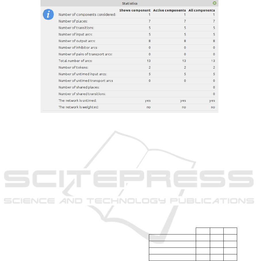
Figure 5: PN Stats extracted from TAPAAL.
that every state is reachable and the number of op-
erations is limited;
• Also, we verified the existence of deadlocks,
which was confirmed in 0.005s or simulation
modes, indicating that the PN design is bounded;
• Finally, in our simulations, we verified that the
network is 4-bounded, satisfying the boundness
criteria.
All these indicators suggest that the proposed
dataflow is safe to develop the proposed application.
After this, we must also verify the synchronous test
results to describe better and understand the proposed
system and its constraints.
4.2 Synchronous Requirement Test
After presenting the results and discussions of the
asynchronous tests, we also discuss the synchronous
test methods. For this matter, we took the elements
displayed in Figure 3 to create the architecture, shown
in Figure 2. For the matter of this test, we divided
our experiment into two stages: first, establishing the
quality factor baseline, and then performing tests that
increase the number of elements in the architecture
and comparing its quality factor to the baseline.
Our objective is to establish a baseline for the φ
i
real-time requirement for each node device in the first
stage. As stated in Section 3.2, this value is a factor of
a time block size, named θ, and an integer number of
blocks, represented by k. This relation is represented
by the equation φ
i
= k
i
× θ. For this matter, we estab-
lished an arbitrary value of θ = 2 ms.
To define each device’s real-time constraint, we
performed three tests in minimal conditions, with pro-
totype elements. In the first test, we performed all
the tasks with an IoT element, a device running the
server with the Business Rule and AI appliance, and
the VIVE interface. In the second one, we exchanged
the VIVE for a Hololens. Finally, in the third test, we
used both interfaces, maintaining the other elements.
In every test, we performed observations of the
lengths l
g,e
of each device’s events. From this data,
we verified the lengths λ
o
i
from the observations of
the desired patterns and established the minimal k
i
value to obtain a relaxed requirement of Q
f
= 0.95.
Table 1 displays the results of these tests. With the k
i
and θ values, we have a single φ
i
for each device.
Table 1: Timing requirement test (k).
1A 1B 1C
AI/Business Rule 23 23 23
IHM-Hololens - 27 34
IHM-VIVE 19 - 22
IoT-GET 1 1 1
From the results, we notice that the third test series
has the most overloaded conditions. Thus, we took
the values of the 1C column as k
i
to build the soft real-
time constraints using θ = 2ms. With these values, we
performed two more experiment series to evaluate the
system performance when increasing parameters.
In the first test, we evaluate the effect of increas-
ing the number of interfaces on the quality of the data
provided by this system. For this matter, we tested
the environment increases the number of VIVE inter-
faces from one to four, measuring the time to perform
all the events with the desired pattern. In the fifth test,
we also added a Hololens interface. Figure 6 displays
the result of this test.
ICEIS 2021 - 23rd International Conference on Enterprise Information Systems
644

Figure 6: Quality Factor Test Results for the First Scenario.
After the first evaluation, we tested the effect of in-
creasing the number of conveyor belts. For this mat-
ter, we explored two propositions: (i) increasing the
number of belts in a single device and (ii) increasing
the number of devices containing the same number of
belts. For both cases, we started with ten simulated
belts, increasing ten more on each iteration. Figure 7
displays the result for the second test. In red is the
result of increasing the number of belts in a single
computer, and in blue it is the result of increasing the
number of computers containing ten belts each.
Figure 7: Quality Factor Test Results for the Second Sce-
nario.
The obtained results indicate that extra VIVE inter-
faces have a minor impact on the appliance soft real-
time quality constraints. Nonetheless, the addition of
a Hololens had a significant impact on the results,
which we also attribute to the first test’s tight con-
straint. Our results also indicate that the quality factor
performs better, at first sight, increasing the number
of belts in a single device. Nevertheless, the loss of
quality is more significant in the single-machine op-
tion when the number of belts is too large. In this
case, it is better to use a distributed architecture.
5 CONCLUSION
In this work, we performed an analysis of the syn-
chronous and asynchronous requirements for creating
Industry 4.0 appliances. At first, we performed a the-
oretical analysis of the main concepts. Then, we ap-
plied the gathered information on a case-study to de-
termine these restrictions on a prototype environment.
In this approach, we state that the main ideas to
cover synchronous and asynchronous aspects of de-
veloping novel appliances for the industrial environ-
ment are the IIoT, DTs, and DES. While the syn-
chronous aspects communicate with the soft real-time
constraints through a QoS matter, the asynchronous
restraints help verify the appliance dataflow and safe
operating conditions.
In our case study, we evaluate these aspects in a
conveyor belt prototype application. The elements of
the appliance are displayed in Figure 3. To test the
asynchronous requirements, we modeled the dataflow
as a classical PN, analyzing the determinism and
boundness as indicators of a safe dataflow. We eval-
uate the soft real-time constraint as a QoS-like matter
in an IIoT environment for the asynchronous aspects.
Our tests indicate the safe operational conditions
from following the proposed asynchronous modeling.
The PN which describes the dataflow is both deter-
ministic and bounded. Our tests also indicate that the
increasing number of data-consuming interfaces has
a minor impact on real-time constraints. Finally, our
synchronous test indicates that the impact of increas-
ing the number of devices connected to the environ-
ment is a preferable method in comparison to over-
loading one device with the acquisition of multiple
belts when the number of belts per device is larger
than 30.
In future work, tests with a higher number of ele-
ments in the architecture could bring new conclusions
as the machine resources were limited. The PN could
also be represented as an Object-Oriented Petri Net
(OOPN) to evaluate its performance over a simula-
tion software. Features like time, conditions, priority,
and rules should be associated with the model repre-
senting the system at a low level, validating its asyn-
chronous requirements over the PN, as suggested by
Masri et al. (Masri et al., 2009).
ACKNOWLEDGEMENTS
The authors would like to thank CAPES, CNPq, and
the Federal University of Ouro Preto for support-
ing this work. This study was financed in part by
the Coordenac¸
˜
ao de Aperfeic¸oamento de Pessoal de
Synchronous and Asynchronous Requirements for Digital Twins Applications in Industry 4.0
645

N
´
ıvel Superior - Brasil (CAPES) - Finance Code 001,
Fundac¸
˜
ao De Amparo a Pesquisa Do Estado De Mi-
nas Gerais - FAPEMIG grant code APQ-01331-18,
and the Instituto Tecnol
´
ogico Vale (ITV).
REFERENCES
Almassalkhi, M., Frolik, J., and Hines, P. (2017). Packe-
tized energy management: asynchronous and anony-
mous coordination of thermostatically controlled
loads. In 2017 American Control Conference (ACC),
pages 1431–1437. IEEE.
Amorim, V. J., Silva, M. C., and Oliveira, R. A. (2019).
Software and hardware requirements and trade-offs in
operating systems for wearables: A tool to improve
devices’ performance. Sensors (Basel, Switzerland),
19(8).
Atzori, L., Iera, A., and Morabito, G. (2010). The internet of
things: A survey. Computer networks, 54(15):2787–
2805.
Bilberg, A. and Hadar, R. (2012). Adaptable and reconfig-
urable lean automation-a competitive solution in the
western industry.
Boschert, S., Heinrich, C., and Rosen, R. (2018). Next gen-
eration digital twin. In Proc. TMCE, pages 209–218.
Las Palmas de Gran Canaria, Spain.
Byg, J., Jørgensen, K. Y., and Srba, J. (2009). Tapaal:
Editor, simulator and verifier of timed-arc petri nets.
In International Symposium on Automated Technology
for Verification and Analysis, pages 84–89. Springer.
Da Xu, L., He, W., and Li, S. (2014). Internet of things in
industries: A survey. IEEE Transactions on industrial
informatics, 10(4):2233–2243.
Doltsinis, S., Ferreira, P., and Lohse, N. (2017). A sym-
biotic human–machine learning approach for produc-
tion ramp-up. IEEE Transactions on Human-Machine
Systems, 48(3):229–240.
Fortino, G., Savaglio, C., and Zhou, M. (2017). Toward
opportunistic services for the industrial internet of
things. In 2017 13th IEEE Conference on Automa-
tion Science and Engineering (CASE), pages 825–
830. IEEE.
Gabor, T., Belzner, L., Kiermeier, M., Beck, M. T., and
Neitz, A. (2016). A simulation-based architecture for
smart cyber-physical systems. In 2016 IEEE Interna-
tional Conference on Autonomic Computing (ICAC),
pages 374–379. IEEE.
Garrocho, C., Ferreira, C. M. S., Junior, A., Cavalcanti,
C. F., and Oliveira, R. R. (2019). Industry 4.0: Smart
contract-based industrial internet of things process
management. In Anais do IX Simp
´
osio Brasileiro de
Engenharia de Sistemas Computacionais, pages 137–
142. SBC.
Holdowsky, J., Mahto, M., Raynor, M. E., and Cotteleer, M.
(2015). Inside the internet of things (iot): A primer on
the technologies building the iot. Deloitte University
Press.
Jezequel, L., Fabre, E., and Khomenko, V. (2015). Factored
planning: From automata to petri nets. ACM Trans-
actions on Embedded Computing Systems (TECS),
14(2):1–25.
Kolberg, D. and Z
¨
uhlke, D. (2015). Lean automa-
tion enabled by industry 4.0 technologies. IFAC-
PapersOnLine, 48(3):1870–1875.
Lasi, H., Fettke, P., Kemper, H.-G., Feld, T., and Hoffmann,
M. (2014). Industry 4.0. Business & information sys-
tems engineering, 6(4):239–242.
Latorre-Biel, J.-I., Faul
´
ın, J., Juan, A. A., and Jim
´
enez-
Mac
´
ıas, E. (2018). Petri net model of a smart fac-
tory in the frame of industry 4.0. IFAC-PapersOnLine,
51(2):266–271.
Lomotey, R. K., Pry, J., and Sriramoju, S. (2017). Wearable
iot data stream traceability in a distributed health in-
formation system. Pervasive and Mobile Computing,
40:692–707.
Masri, A., Bourdeaud’Huy, T., and Toguyeni, A. (2009).
Performance analysis of ieee 802.11 b wireless net-
works with object oriented petri nets. Electronic Notes
in Theoretical Computer Science, 242(2):73–85.
Qi, Q. and Tao, F. (2018). Digital twin and big data to-
wards smart manufacturing and industry 4.0: 360 de-
gree comparison. Ieee Access, 6:3585–3593.
Romero, D., Stahre, J., Wuest, T., Noran, O., Bernus, P.,
Fast-Berglund,
˚
A., and Gorecky, D. (2016). Towards
an operator 4.0 typology: a human-centric perspec-
tive on the fourth industrial revolution technologies. In
Proceedings of the International Conference on Com-
puters and Industrial Engineering (CIE46), Tianjin,
China, pages 29–31.
Rosen, R., Von Wichert, G., Lo, G., and Bettenhausen,
K. D. (2015). About the importance of autonomy and
digital twins for the future of manufacturing. IFAC-
PapersOnLine, 48(3):567–572.
Saldivar, A. A. F., Li, Y., Chen, W.-n., Zhan, Z.-h., Zhang,
J., and Chen, L. Y. (2015). Industry 4.0 with cyber-
physical integration: A design and manufacture per-
spective. In 2015 21st international conference on
automation and computing (ICAC), pages 1–6. IEEE.
Samie, F., Tsoutsouras, V., Xydis, S., Bauer, L., Soudris,
D., and Henkel, J. (2016). Distributed qos manage-
ment for internet of things under resource constraints.
In Proceedings of the Eleventh IEEE/ACM/IFIP Inter-
national Conference on Hardware/Software Codesign
and System Synthesis, pages 1–10.
Samsung Research (2020). 6G the next hyper-connected
experience for all.
Schluse, M., Priggemeyer, M., Atorf, L., and Rossmann, J.
(2018). Experimentable digital twins—streamlining
simulation-based systems engineering for industry
4.0. IEEE Transactions on Industrial Informatics,
14(4):1722–1731.
Silva, M. and Oliveira, R. (2019). Analyzing the effect
of increased distribution on a wearable appliance. In
2019 IEEE 43rd Annual Computer Software and Ap-
plications Conference (COMPSAC), volume 2, pages
13–18. IEEE.
Sisinni, E., Saifullah, A., Han, S., Jennehag, U., and Gid-
lund, M. (2018). Industrial internet of things: Chal-
lenges, opportunities, and directions. IEEE Transac-
tions on Industrial Informatics, 14(11):4724–4734.
ICEIS 2021 - 23rd International Conference on Enterprise Information Systems
646

Taneja, M. and Davy, A. (2017). Resource aware place-
ment of iot application modules in fog-cloud comput-
ing paradigm. In 2017 IFIP/IEEE Symposium on Inte-
grated Network and Service Management (IM), pages
1222–1228. IEEE.
Tao, F. and Zhang, M. (2017). Digital twin shop-floor: a
new shop-floor paradigm towards smart manufactur-
ing. Ieee Access, 5:20418–20427.
Vogel-Heuser, B. and Hess, D. (2016). Guest edito-
rial industry 4.0–prerequisites and visions. IEEE
Transactions on Automation Science and Engineer-
ing, 13(2):411–413.
Yamaguchi, S., Tsugawa, S., and Nakahori, K. (2016).
An analysis system of iot services based on agent-
oriented petri net pn2. In 2016 IEEE International
Conference on Consumer Electronics-Taiwan (ICCE-
TW), pages 1–2. IEEE.
Yang, R., Li, B., and Cheng, C. (2014). A petri net-based
approach to service composition and monitoring in the
iot. In 2014 Asia-Pacific Services Computing Confer-
ence, pages 16–22. IEEE.
Zhang, Y., Wang, W., Wu, N., and Qian, C. (2015). Iot-
enabled real-time production performance analysis
and exception diagnosis model. IEEE Transactions
on Automation Science and Engineering, 13(3):1318–
1332.
Synchronous and Asynchronous Requirements for Digital Twins Applications in Industry 4.0
647
