
Systems-theoretic Safety Assessment of Teleoperated Road Vehicles
Simon Hoffmann and Frank Diermeyer
Institute of Automotive Technology, Technical University of Munich, Boltzmannstr. 15, Garching b. M
¨
unchen, Germany
Keywords:
Teleoperated Driving, Automated Driving, Hazard Analysis, STPA, Safety.
Abstract:
Teleoperation is becoming an essential feature in automated vehicle concepts, as it will help the industry
overcome challenges facing automated vehicles today. Teleoperation follows the idea to get humans back
into the loop for certain rare situations the automated vehicle cannot resolve. Teleoperation therefore has the
potential to expand the operational design domain and increase the availability of automated vehicles. This is
especially relevant for concepts with no backup driver inside the vehicle. While teleoperation resolves certain
issues an automated vehicle will face, it introduces new challenges in terms of safety requirements. While
safety and regulatory approval is a major research topic in the area of automated vehicles, it is rarely discussed
in the context of teleoperated road vehicles. The focus of this paper is to systematically analyze the potential
hazards of teleoperation systems. An appropriate hazard analysis method (STPA) is chosen from literature
and applied to the system at hand. The hazard analysis is an essential part in developing a safety concept (e.g.,
according to ISO26262) and thus far has not been discussed for teleoperated road vehicles.
1 INTRODUCTION
Automated Driving (AD) is, besides electrification of
road vehicles, one of the biggest challenges and op-
portunities the automotive industry is currently fac-
ing. Original Equipment Manufacturer (OEMs), as
well as research institutes, are investing significant ef-
fort into getting Automated Driving Systems (ADS)
1
on public roads. To describe the degree of automation
of a specific driving automation system, a taxonomy
was introduced SAE International (2018). This tax-
onomy differentiates between six different levels from
L0 “No Driving Automation” to L5 “Full Driving Au-
tomation.” Only L3 - L5 systems, which are capa-
ble of performing the Dynamic Driving Tasks (DDT)
on a “sustained basis” SAE International (2018), are
considered ADS. Below L3, even if the vehicle is
performing longitudinal and lateral driving tasks on
a sustained basis, the human driver is responsible
for the Object and Event Detection and Response
(OEDR). For L3-ADS, the system performs the
whole DDT including OEDR. If a DDT performance-
relevant system failure occurs or when the driving au-
tomation system is about to leave its Operational De-
sign Domain (ODD), the fallback-ready user has to
take over. Up to this point, a human driver is required
1
Taxonomy according to SAE International (2018) is used
throughout this paper
inside the vehicle. As indicated by Abe (2019), appli-
cations such as public transportation or taxi services
could strongly benefit if human drivers are replaced
by the ADS and the system is responsible for DDT-
fallback itself (L4+). According to SAE International
(2018), the system has to perform a DDT-fallback by
achieving a minimal risk condition, which could be a
safe stop at an appropriate place. This, however, re-
quires the ADS to be fully functional and has to be
separated from the failure mitigation strategy, which
is required to stop the vehicle in case of critical sys-
tem failures.
The previous paragraph shows the different levels
of ADS and the role of humans in context of the driv-
ing task. SAE International (2018) indicates that even
an L4+ vehicle, which does not require a user inside
the vehicle, depends on some fallback strategies to
stop the vehicle in certain situations. A fallback driver
might still be able to perform the DDT and might not
be dependent on degraded or failing system compo-
nents. The absence of such a fallback driver results
in the vehicle and its passengers being stranded and
obstructing traffic. The higher the reliability of such
a system, the higher the acceptance and profitability
of ADS will be. ADS are getting better over time.
However, taking into account every edge case appear-
ing on public roads might not be feasible. Therefore,
having a reliable fallback option for L4+ vehicles will
446
Hoffmann, S. and Diermeyer, F.
Systems-theoretic Safety Assessment of Teleoperated Road Vehicles.
DOI: 10.5220/0010438904460456
In Proceedings of the 7th International Conference on Vehicle Technology and Intelligent Transport Systems (VEHITS 2021), pages 446-456
ISBN: 978-989-758-513-5
Copyright
c
2021 by SCITEPRESS – Science and Technology Publications, Lda. All rights reserved

not only decrease the time-to-market launch but also
the acceptance and profitability of L4+ ADS e.g., in
public transportation or logistics.
To solve this problem, the concept of teleoper-
ation can be used Georg et al. (2018); Bout et al.
(2017). After the ADS dedicated vehicle comes to
a stop by way of its integrated DDT-fallback func-
tion or following a failure mitigation strategy, the ve-
hicle contacts a control center. A concept for such a
control center is proposed by Feiler et al. (2020). A
remote operator has to analyze the problem and can
choose among different options to resolve the situa-
tion (Feiler et al., 2020). One of them remotely con-
trols the vehicle until the ADS can continue the DDT
itself. Alternatively, the operator could teleoperate the
vehicle to the next bus station or to a vehicle repair
center.
Vehicle sensor information is sent to the operator
via the cellular network. The operator has to com-
prehend the situation and the vehicle’s surroundings
based on the sensor information and send control sig-
nals back to the vehicle. This introduces new prob-
lems to the system, such as latencies, reduced situa-
tion awareness or connection losses. The presented
work analyzes those problems and identifies further
hazards related to teleoperated road vehicles. This is
a necessary step in developing a holistic safety con-
cept for teleoperated road vehicles. Before teleoper-
ated road vehicles are analyzed in Section 5, a short
overview on related work regarding safety assessment
and teleoperation is given in Section 2. Further a short
overview on the used method (Section 3), and the sys-
tem this method is applied to (Section 4), is provided.
2 RELATED WORK
Before analyzing the system of teleoperated road ve-
hicles, a literature review on their problems and also
identified solutions is given. Furthermore the advan-
tages of a systems-theoretic approach are outlined and
related work regarding its application in a automotive
context is presented.
2.1 Teleoperation of Road Vehicles
Teleoperation is a widely used concept for different
applications. It is often utilized to reach hazardous or
inaccessible areas, such as in space-robotics or deep-
sea exploration. Bensoussan and Parent (1997) apply
this concept to road vehicles for distributing car shar-
ing vehicles. With the development of AD, the fo-
cus of teleoperation is to provide a fallback for ADS.
However, teleoperation itself is prone to some prob-
lems that are the focus of research as long as this re-
search area exists.
Adams (1961) shows the decreasing performance
of humans in path-following experiments depend-
ing on transmission latencies. Sheridan and Fer-
rell (1963) and Ferrell (1965) show increasing task-
completion times with increasing delay. Variable la-
tencies in the context of driving tasks are investigated
by Davis et al. (2010), Gnatzig et al. (2013) and Liu
et al. (2017). Variable delay are shown to be even
worse than constant transmission delay for driving
tasks. Different solutions are proposed to overcome
the negative impact of latencies for teleoperated road
vehicles. Chucholowski (2013) proposed a predictive
display, which increases driving performance under
delay. Gnatzig et al. (2012), Hosseini et al. (2014)
and Fong (2001) utilize more automation on the robot
side by sending trajectories or waypoints to the vehi-
cle. Certain control loops are closed within the robot
and the operator does not act on a stabilization level,
which is prone to latencies. Lichiardopol S. (2007)
provides a categorization of the different teleopera-
tion concepts and the human and robot responsibili-
ties. Tang et al. (2014) propose a method that takes
into account connection losses in teleoperated road
vehicles and brings the vehicle to a safe stop.
Another teleoperation problem is the situation
awareness of the operator not being located in the ve-
hicle. Georg et al. (2018), Hosseini and Lienkamp
(2016) and Bout et al. (2017) investigate the influ-
ence of Head Mounted Displays (HMDs) e.g., on situ-
ation awareness. Georg et al. (2020b) investigates the
effects of videoquality, videocanvases and displays
on situation awareness. Hosseini et al. (2016) and
Schimpe and Diermeyer (2020) propose solutions to
support the operator with the driving task and over-
come the negative effects of situation awareness and
latencies regarding collisions.
2.2 Safety Assessment
Section 2.1 shows that different aspects reducing the
safety of teleoperated road vehicles are already ad-
dressed in research. Additionally, different concepts
and solutions are proposed in literature to overcome
certain problems. To ensure functional safety in an
automotive context, the ISO 26262 standard exists
(ISO, 2018). Section 3 of ISO 26262, which results
in a functional safety concept, requires a hazard and
risk analysis of the system at hand. Usually, haz-
ard analysis methods such as Hazard and Operabil-
ity Study (HAZOP), Failure Mode and Effect Anal-
ysis (FMEA) or Fault Tree Analysis (FTA) are ap-
plied to systematically identify potential hazards of
Systems-theoretic Safety Assessment of Teleoperated Road Vehicles
447

the system. According to Placke et al. (2015), tra-
ditional methods tend to focus on component fail-
ures. However, accidents often happen due to com-
ponent interaction, regardless of individual compo-
nents or software working correctly (Thomas et al.,
2015). Software-related accidents are often caused by
flawed requirements instead of coding errors. How-
ever, flawed requirements are hard to capture us-
ing traditional failure-based methods (Thomas et al.,
2015).
To complement functional safety covered by
ISO 26262, ISO/PAS 21448 addresses the Safety of
the Intended Functionality (SOTIF) (ISO, 2019). The
scope of ISO/PAS 21448 is to address hazards, re-
sulting from functional insufficiencies of the intended
functionality or foreseeable misuse (ISO, 2019). Be-
sides the previously mentioned hazard analysis meth-
ods, System-Theoretic Process Analysis (STPA) is
listed in ISO/PAS 21448. STPA was proposed by
Leveson (2011), to overcome certain flaws in the ex-
isting methods. This system engineering approach
follows the idea to formulate safety as a control prob-
lem rather than a reliability problem (Leveson, 2011).
STPA has the ability to consider interactions between
different types of components, such as software, hard-
ware or humans (Placke et al., 2015). According to
Thomas et al. (2015), “STPA is a top-down hazard
analysis method designed to go beyond traditional
component failures to also identify problems such as
dysfunctional interactions, flawed requirements, de-
sign errors, external disturbances, human error and
human-computer interaction issues”. Since STPA
was introduced, it is applied to a range of different
systems, also in an automotive context. Sulaman et al.
(2014) investigates a forward collision avoidance sys-
tem using STPA and experiences advantages with re-
spect to time effort and covering the dynamic system
behavior within the analysis. Raste et al. (2015) uses
STPA to analyze a fallback strategy for AD. Oscars-
son et al. (2016) states that other methods are not
designed to consider multiple vehicles in the analy-
sis. Therefore, STPA is used to analyse a cooperative
driving system in (Oscarsson et al., 2016). Stolte et al.
(2016) uses the STPA to analyse the actuation sys-
tem of an automated vehicle and proposes a way to
better include quasi-continuous control actions in the
analysis. Bagschik et al. (2017) performes an STPA
on an unmanned protective vehicle for highway road
work. In Abdulkhaleq et al. (2018), STPA is applied
to identify safety in use requirements for an ADS.
Abdulkhaleq et al. (2018) finds that the interaction
of ADS with the human, environment or other traf-
fic participants could be sufficiently addressed. Suo
et al. (2017) and Mallya et al. (2016) propose ways to
integrate STPA into the ISO26262 process.
2.3 Aim of Present Work
As shown in Section 2.1 multiple solutions were de-
veloped to address certain problems of teleoperated
driving. However, to the knowledge of the authors,
there is no literature which attempts to systematically
identify the risks and hazards of teleoperated road ve-
hicles. Since this is an important aspect in developing
a safety concept, a systematic analysis is performed in
the presented work. Due to the advantages in STPA’s
handling of human flaws and errors, as well as its suc-
cessful application in different automotive situations,
STPA is applied to the system at hand.
3 AN OVERVIEW OF STPA
Before applying the STPA to the teleoperation system
in Section 5, an overview of this method is given. The
STPA is divided into four steps, as shown in Figure 1.
While step 1 and step 2 are considered as preparation,
steps 3 and 4 make up the main analysis of the system.
The most important aspects of the individual steps are
provided in Section 3.1 to Section 3.4. For further
information on STPA, refer to (Leveson and Thomas,
2018).
Step 1:
Purpose of
Analysis
Step 2:
Control
Structure
Step 3:
Unsafe
Control A.
Step 4:
Causal
Factors
Preparation Main Analysis
Losses
System Hazards
System Constr.
Control Structure UCA
Controller Constr.
Loss Scenarios
Figure 1: Overview on the STPA process and the outcome
of the individual steps.
3.1 Defining the Purpose of the Analysis
The first step of performing an STPA involves defin-
ing the purpose of the analysis, which involves losses,
system boundaries, system-level hazards and System-
level Constraints (SCs). According to Leveson and
Thomas (2018, p. 16), a loss could be anything of
value to a stakeholder, while a hazard is: “A system
state or set of conditions that, together with a partic-
ular set of worst-case environmental conditions, will
lead to an accident (loss)” (Leveson, 2011, p. 184).
To define the system-level hazards, the system and its
VEHITS 2021 - 7th International Conference on Vehicle Technology and Intelligent Transport Systems
448

boundaries need to be determined. Finally, the SCs
are identified. According to Leveson and Thomas
(2018), they can be simply formulated by inverting
the hazards or by specifying what needs to happen if
a hazard occurs.
3.2 Control Structure
Modeling the system as a control structure is a cen-
tral aspect of STPA, that formulates safety as a con-
trol problem. Therefore, the next step of the STPA
requires generating a hierarchical control structure of
the system. At a minimum, the control structure con-
sists of a controller and a controlled process. The con-
troller has some control authority over the controlled
process by Control Actions (CAs) and receives feed-
back from the controlled process. The controller has
some internal control algorithm which calculates and
provides the CA. The process model of the controller
represents the internal beliefs of the controller, for ex-
ample, about the controlled process or the environ-
ment (Leveson and Thomas, 2018, p. 22-25).
3.3 Identifying Unsafe Control Actions
After the control structure is developed, the main
analysis starts with identifying Unsafe Control
Actions (UCAs). “An Unsafe Control Action (UCA)
is a control action that, in a particular context and
worst-case environment, will lead to a hazard”
(Leveson and Thomas, 2018, p. 35). To identify
UCAs, every CA is analyzed with respect to whether
providing, not providing, providing too long/short
or providing too early/late could lead to one of the
hazards identified in step 1. It is important to specify
a context which makes the CA unsafe. According
to Leveson and Thomas (2018, p. 36), a context
could be an environmental condition, state of the
controlled process, or previous actions or parameters.
Thomas (2013) extends the STPA through systematic
means to identify context variables. Accordingly,
he identified process model variables that represent
the information or beliefs a controller requires about
the controlled process or the environment to provide
a CA. Thomas (2013) derived the system level
variables from the system level hazards. As a next
step, discrete values are assigned to the variables.
To identify UCAs, different combinations of the
values—the context—are checked, if providing or
not providing the CA in this context can lead to a
hazard. Controller constraints can further be derived
based on the UCA.
3.4 Identifying Causal Factors
The final step of STPA is to identify the potential
causes of unsafe behavior. According to Thomas
(2013, p. 169), safety constraints can be violated
either by a controller providing a UCA (case 1) or
by an appropriate CA not being followed (case 2).
To identify potential causes for the first case, the en-
tire feedback path, including the controller itself (pro-
cess model, control algorithm) needs to be analyzed.
Potential external influences or communications to
other controllers also need to be considered. To find
causes for appropriate CA not being followed, the
CA path needs to be analyzed, including actuators,
the controlled process, disturbances, environmental
influences or other controllers. Thomas (2013, p.
169) provides a classification of Causal Factors (CFs),
which can be used as guidance to analyze the control
structure.
4 SYSTEM DESCRIPTION
In this section, the system to be analyzed within the
present work is discussed. An overview is shown in
Figure 2. The vehicle perceives its environment us-
ing camera sensors. This sensor information, together
with the vehicle’s internal states, is sent to the con-
trol center. A virtual representation of the vehicle’s
surroundings is generated within the interface (Georg
and Diermeyer, 2019). This information is provided
to the operator using displays. Based on the feedback,
the operator can provide control signals using a steer-
ing wheel, throttle and brake pedal actuators. A vehi-
cle steering wheel angle and desired velocity are cal-
culated based on these inputs. The feedback, as well
as the control signals, are transmitted to the vehicle
using the cellular network. A detailed overview of
the individual components, including latencies within
the actuators and sensors chain, is published by Georg
et al. (2020a).
Vehicle
4G/5G Control Center
Interface
Operator
control signals
feedback
Figure 2: Overview of the teleoperation system.
Systems-theoretic Safety Assessment of Teleoperated Road Vehicles
449

5 APPLICATION OF STPA ON
TELEOPERATION SYSTEM
In the following sections the individual steps, intro-
duced in Section 3, are applied to the teleoperation
system in Section 4.
5.1 Defining the Purpose of the Analysis
We identified the following stakeholders to the teleop-
eration system: vehicle passengers, other traffic par-
ticipants and property owners. After identifying the
stake or value of each stakeholder, we determined the
losses L-1 to L-2. Leveson and Thomas (2018, p.
148) provided some losses and hazards for automo-
tive industry. Since these did fit for our system, we
borrowed L-1, L-2, H-1 and H-5 from Leveson and
Thomas (2018, p. 148).
L-1 Loss of life or injury to people
L-2 Damage to ego vehicle or objects outside the ego
vehicle
If the system in Section 4 is part of a taxi fleet, the
service provider could be a stakeholder with its own
goals. The operator or an OEM may also have some
stake in the system. An OEM could be concerned
about its image, and “Loss of OEM image” could be
another loss. The stake of vehicle passengers could
also be comfort or punctuality. However, only L-1
to L-2 are considered within the scope of this work.
The system-level hazards are identified in the next
step. Following the ideas of Leveson and Thomas
(2018), H-1 to H-4 could lead to a loss under some
worst-case environmental condition:
H-1 System does not maintain safe distance from
nearby objects [L-1, L-2]
H-2 System leaves intended lane [L-1, L-2]
H-3 System behavior is breaking the law (e.g., red
lights, stop sign) [L-1, L-2]
H-4 Vehicle exceeds safe operating envelope for
environment (speed, lateral/longitudinal forces)
[L-1, L-2]
The losses that individual hazards could cause are
specified in brackets. The formulated system-level
hazards and losses are very general and abstract.
However, this is intended by Leveson and Thomas
(2018). The hazards should not be on a component
level and no causes for hazards should be part of the
hazard description. The causes for hazards on a com-
ponent level are investigated in the following STPA
steps. Unnecessary detail should be omitted to bet-
ter identify missing aspects and keep the list manage-
able (Leveson and Thomas, 2018, p. 19). Leveson
and Thomas (2018) propose refining the hazards into
sub-hazards in a later step if required. SCs can be
identified based on the identified hazards. Only two
examples are provided within the scope of this work.
SC-1 The system must always be able to react on ob-
stacles [H-1]
SC-2 If the system exceeds its dynamic boundaries,
this needs to be detected and countermeasures
need to be taken [H-4]
5.2 Control Structure
An STPA control structure for the teleoperation sys-
tem presented in Section 4 is shown in Figure 3.
Operator
Interface
Vehicle Dynamics
Environment
Change SWA
Brake cmd.
Throttle cmd.
Lane, Objects,
Signs, Velocity,
Veh. path
Change vel.,
Change de-
sired SWA
Actual vel.
Actual SWA
Visual
env.
Driving
behav.
Physical
feedback
Figure 3: STPA control structure of the teleop. system.
The Operator provides CAs, such as the change Steer-
ing Wheel Angle (SWA) command, brake command
and throttle command to the interface. Thus, only
the primary driving tasks (Bubb, 2003) are consid-
ered for the analysis. According to Stolte et al. (2016)
“change SWA” instead of the continous SWA is used.
However, “hold SWA” was not included as a sepa-
rate command, but considerd as “not providing” the
“change SWA” command in Section 5.3. The opera-
tor receives visual feedback from the interface. The
display and input devices are not part of the control
structure to reduce complexity. They are, together
with sensors and actuators, added in step 4 of the anal-
ysis. The human operator is modeled as a controller
in the provided control structure. Therefore, the hu-
man operator can be included in the analysis and hu-
man flaws or errors can be identified which is one of
the advantages of using STPA. The human operator
also has some control algorithm and process models.
Rasmussen (1983) proposed the three levels of per-
formance of skilled human operators. This is a model
describing the cognitive processes of humans from in-
put to actions. The model distinguishes between three
different layers: skill-based behavior, rule-based be-
havior and knowledge-based behavior. In (Donges,
VEHITS 2021 - 7th International Conference on Vehicle Technology and Intelligent Transport Systems
450

2016), these layers are assigned to the different layers
of driving tasks (stabilization, guidance and naviga-
tion) proposed by Donges (1982). Therefore, we con-
sider this model a control algorithm for the human op-
erator in context of a driving task. The process model
of a human operator is called a mental model Thomas
et al. (2015). Rasmussen (1983) states that the differ-
ent mental models humans create are the reason for
human performance in coping with complexity. Since
the operator is not located inside the vehicle, the men-
tal model is largely dependent and updated by the re-
ceived feedback and the presentation of the feedback.
Based on the operator CAs, the interface calculates a
change velocity command and a change desired SWA
command. The interface does also contain certain be-
liefs about the controlled process, such as the steer-
ing ratio, sensor positions, etc. These beliefs make
up the process model for the interface. The interface
receives feedback from the physical vehicle and the
vehicle’s environment, creates a scene representation
of the environment and provides this information to
the operator. Further information on the interface is
published by Georg and Diermeyer (2019). The envi-
ronment is not part of the system itself. Nevertheless,
we decided to include it in the control structure, sim-
ilar to Placke et al. (2015), to indicate where certain
information comes from.
The desired velocity and SWA is transmitted to
the vehicle via wireless network. Even if the actual
signal sent to the vehicle is a desired velocity, it can
be advantageous for the analysis to split the CA into
increase and decrease velocity. The network is not vi-
sualized within Figure 3. Similar to sensors and actu-
ators, the information about the network is neglected
in this step. What happens to the CA on its way to the
controlled process is part of step 4 during the analy-
sis.
The presented control structure is an abstract rep-
resentation of the real system. The control structure in
Figure 3 is not dependent on any implementation de-
tails or component decisions and is therefore valid for
a variety of different teleoperated road vehicles. The
vehicle in Figure 3 is only represented by its dynamic
behaviour. The reason is to perform some abstraction
and simplification. From this, we cannot perform a
detailed analysis on the vehicle internal control loops.
However, we can still consider the interaction of the
vehicle and other entities since the input and outputs
stay the same. The vehicle control loop is not intrinsic
to the teleoperation concept itself. Stolte et al. (2016)
performed an STPA solely on the vehicle actuation
system in the context of AD. The goal of this analysis
is to investigate conceptual problems of teleoperated
driving in a first step and not some implementation
or hardware specific hazards. We are also not includ-
ing certain available safety measures (Section 2.1), to
not overlook important aspects or better solutions dur-
ing the analysis. The fact that STPA is a top-down
approach allows to make an analysis before specific
components and design decisions are made. The re-
sults can therefore be considered in the later develop-
ment.
5.3 Identifying Unsafe Control Actions
Applying the approach of Thomas (2013), we ended
up with the process model variables in Table 1, mak-
ing up the contexts. In reality, road networks or traffic
regulations are more complex, especially when con-
sidering urban situations. However, to reduce com-
plexity for a first analysis, this abstract representation
was chosen.
Table 1: Process model variables making up the contexts.
Conditions Values
Vehicle motion - Stopped
- Moving
Traffic participants
relative to ego vehicle
- None
- Same lane in front
- Same lane behind
- Neighboring lane
Road Surface - High µ
- Low µ
Regulatory elements
(signs, lights, etc.)
- Yes
- No
Lane -
˙
κ 6= 0
-
˙
κ = 0
Due to the high amount of identified UCAs, only
the UCAs related to the brake command are presented
in Table 2. If a certain condition is not explicitly
mentioned within the UCA description, all its values
could lead to the specified hazard. The controller con-
straints, resulting from UCAs, are not explicitly men-
tioned here.
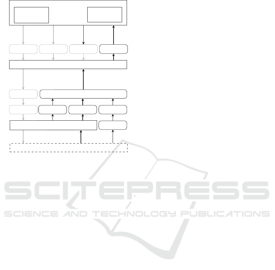
5.4 Identifying Causal Factors
To identify potential causes for the UCAs provided
in Table 2, how the feedback is provided to the con-
trollers and how control actions are executed need to
be considered. The control structure is updated ac-
cordingly in Figure 4 by including sensors, actuators,
network, mental model and control algorithm. Enti-
ties that are not explicitly addressed within this chap-
ter are grayed out.
To identify CFs for UCA-1 an examination of
causes in the highlighted entities within Figure 4 is
Systems-theoretic Safety Assessment of Teleoperated Road Vehicles
451
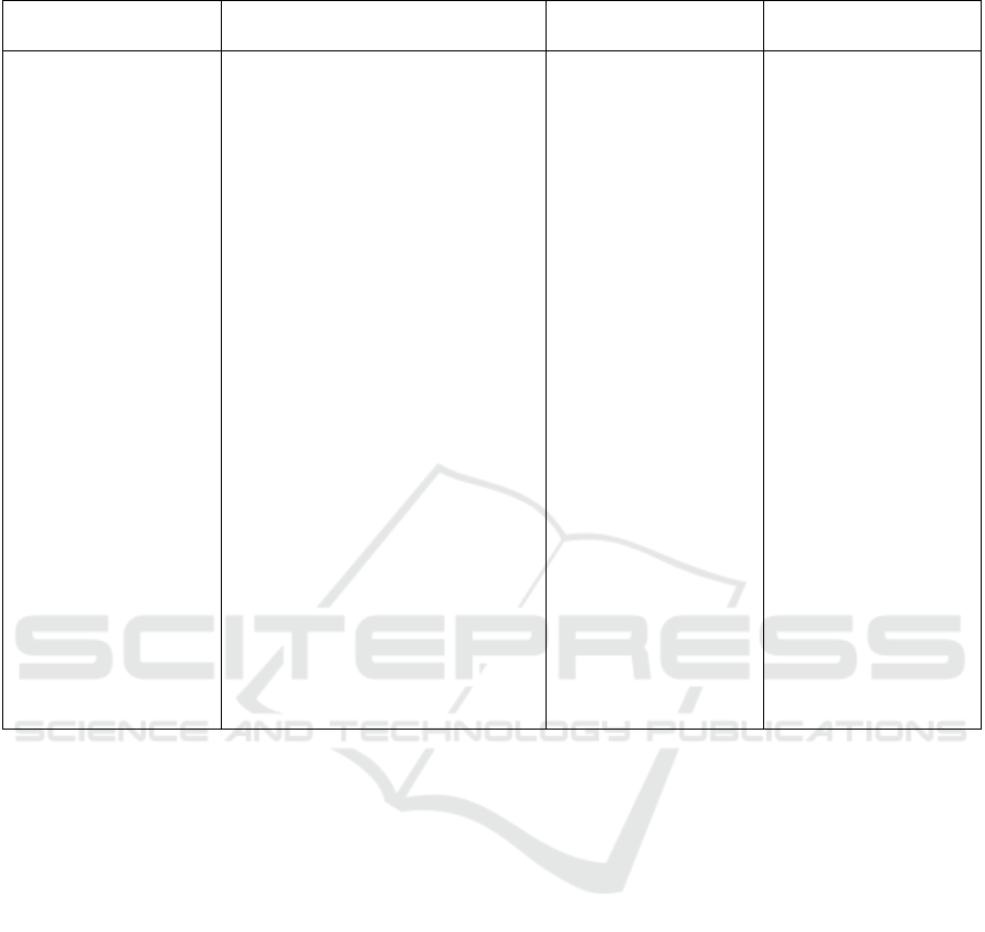
Table 2: Unsafe Control Actions for Brake Command.
Not providing causes
hazards
Providing causes hazards To early, too late, out
of order
Stopped too soon, ap-
plied too long
UCA-1: O. does not
provide s
Bp
, if vehi-
cle is moving and ob-
ject is in/approaching
same lane to the front
[H-1]
UCA-2: O. does not
provide s
Bp
, if vehi-
cle is moving and reg-
ulatory elements are
present [H-3]
UCA-3: O. does not
provide s
Bp
, if vehi-
cle is moving on low
µ and
˙
κ 6= 0 [H-4, H-
2]
UCA-4: O. does not
provide s
Bp
, if vehi-
cle is moving on low
µ,
˙
κ 6= 0 and objects
in/approaching neigh-
boring lane [H-1]
UCA-5: O. provides excessive
s
Bp
, if vehicle is moving and
object in/approaching same lane
to the rear [H-1]
UCA-6: O. provides excessive
s
Bp
, if vehicle is moving and no
obstacle in/approaching same lane
to the front [H-3]
UCA-7: O. provides insufficient
or excessive s
Bp
, if vehicle is
moving on low µ and
˙
κ 6= 0 [H-4,
H-2]
UCA-8: O. provides excessive
s
Bp
, if vehicle is moving on low
µ and
˙
κ 6= 0 and an obstacle is
in/approaching neighboring lane
[H-1, H-2]
UCA-9: O. provides insufficient
s
Bp
, if vehicle is moving and
object is in/approaching same
lane to the front [H-1]
UCA-10: O. provides insufficient
s
Bp
, if vehicle is moving and
regulatory elements are present
[H-3]
UCA-11: O. provides
s
Bp
too early, if ve-
hicle is moving and
object in/approaching
same lane to the rear
[H-1]
UCA-12: O. provides
s
Bp
too late, if ve-
hicle is moving and
object in/approaching
same lane to the front
[H-1]
UCA-13: O. provides
s
Bp
too late, if vehi-
cle is moving and reg-
ulatory elements are
present [H-3]
UCA-14: O. provides
s
Bp
too late, if vehi-
cle is moving on low
µ and
˙
κ 6= 0 [H-2, H-
4]
UCA-15: O. stops
providing s
Bp
to
soon, if vehicle is
moving and object
in/approaching lane
to the front [H-1]
UCA-16: O. stops
providing s
Bp
to soon,
if vehicle is moving
and regulatory el-
ements are present
[H-3]
UCA-17: O. stops
providing s
Bp
to soon,
if vehicle is moving
on low µ and
˙
κ 6= 0
[H-2, H-4]
required. Starting with the operator who initially pro-
vided UCA-1, the operator’s control algorithm and
mental model need to be considered potential causes.
The operator might have multiple mental models to
represent the environment, the interface and the ve-
hicle. One reason for UCA-1 could be an inconsis-
tent, incomplete or incorrect mental model, which
does not (completely) represent the reality. This is
often referred to as situation awareness (Leveson and
Thomas, 2018, p. 188). When thinking about the in-
formation the operator requires to avoid UCA-1, the
following CFs regarding the mental model can be for-
mulated:
CF-1 Mental model contains no/wrong information
about surrounding objects and their relative
position to the ego vehicle.
CF-2 Mental model contains no/wrong information
about the motion or dimensions of the ego ve-
hicle.
CF-3 Mental model contains no/wrong information
about vehicle/actuator/interface behaviour.
In a next step, we can identify further reasons for
the above mentioned CFs. The mental models are
constantly updated by inputs, training or experience
(Leveson and Thomas, 2018, p. 185). Potential rea-
sons for the above mentioned CFs could be:
CF-4 Mental model is not/insufficiently updated
due to outer influences of the operator such
as distraction.
CF-5 Mental model is not/insufficiently updated
due to insufficient representation of the infor-
mation (e.g., wrong modality).
CF-6 Changes in the controlled process (e.g.,
changing vehicle) results in incorrect mental
model.
Operator visual impairment or health issues could
also be a reason. Further CFs can be identified by
analyzing the feedback path in Figure 4 from environ-
ment (bottom) to operator (top). Starting with visual
feedback the following CFs are identified:
CF-7 Object is not within the field of view of the
camera sensor.
VEHITS 2021 - 7th International Conference on Vehicle Technology and Intelligent Transport Systems
452
Operator
Mental
Model
Control
Algorithm
Steeringw. Throttlep. Brakep. Display
Interface
Network
Actuators
Network
Encoder
IMU
SW-Sens
Camera
Vehicle Dynamics
Environment
Change
SWA
Brake
cmd
Throttle
cmd
Change vel.,
Change
desired SWA
Driving
behav.
Lanes,
Obj.,
Signs
Velocity
Veh path
Visual
feedb.
Visual feedb.,
Actual vel.,
Actual SWA
Physical
feedb.
Figure 4: Control Structure of the teleoperation system.
CF-8 Object is obscured by dirt, water or reflections
on the lens.
CF-9 Object is not visible to the camera sensor due
to darkness, fog, rain, etc.
The feedback of the environment itself cannot be
missing or incorrect, since it represents reality. Sen-
sors like the camera, however are only able to capture
parts of the reality, which is represented by CF-7 to
CF-9. In case the light reflected by the object reaches
the camera sensor, the following CFs could still occur
in the camera or the following encoding step.
CF-10 No or inadequate operation of the camera, en-
coder, Inertial Measurement Unit (IMU) or
SWA-sensor (hardware or power failure).
CF-11 Camera, IMU or SWA-sensor is not providing
output because of connection errors.
CF-12 Measurement inaccuracies in camera due to
color and spatial discretization of the reality
could result in the operator being unaware of
the object.
CF-13 Measurement inaccuracies in IMU or SWA-
sensor leading to wrong operator beliefs about
vehicle movement. This could falsely result
in no collision within the operator’s mental
model.
CF-14 Inaccurate information about distances
through lens distortion could lead to wrong
distances between the predicted vehicle path
and the object within the operator’s mental
model.
CF-15 Information loss by image compression of the
encoder could result in a hardly detectable ob-
ject for the operator.
The network is one of the most critical parts within
the whole teleoperation system. It contributes to the
following CFs of UCA-1:
CF-16 No network connection at current vehicle lo-
cation. The feedback about the object is not
provided to the operator.
CF-17 Network is dropping information (packet
loss). The feedback about the object is not
provided to the operator.
CF-18 Network inserts wrong information or
changes the order of information. Wrong
feedback is provided to the operator.
The interface pre-processing the incoming sensor in-
formation also contributes to the list of CFs. The in-
dividual camera streams need to be visualized and
placed relative to each other. Therefore, extrinsic
and intrinsic camera parameters are required. The in-
terface also provides feedback about the current and
future vehicle movement. This information can be
calculated e.g., based on the actual SWA and a dy-
namic model of the vehicle. This model is part of the
interface process model and contains certain beliefs
and simplifications about the real vehicle. The same
SWA, for example, results in different vehicle trajec-
tories depending on the vehicle, road friction coeffi-
cient or other parameters.
CF-19 Interface not working due to power or hard-
ware failure.
CF-20 Interface uses wrong beliefs about camera po-
sition and calibration leading to wrong visual-
ization of objects relative to the vehicle.
CF-21 Wrong beliefs about vehicle or environmental
parameters (friction coefficient µ) results in an
incorrect predicted path. Therefore the object
could falsely be located outside the predicted
path.
Finally, the display can also be a cause for the op-
erator not (correctly) updating its mental model and
therefore resulting in UCA-1:
CF-22 Display not working due to power or hardware
failure
CF-23 Display reducing information by dropping
frames or low resolution
CF-24 Reflections or dirt on screen masking infor-
mation
Systems-theoretic Safety Assessment of Teleoperated Road Vehicles
453

CF-1 to CF-24 are the CFs related to the feedback
path and the mental model of the operator. But
the control algorithm of the operator can also cause
UCA-1. As mentioned earlier, the control algorithm
of the operator is described using the target-oriented
behavior model of Rasmussen (1983). The driving
task the operator is failing to perform in UCA-1 can
be assigned to the guidance and stabilization task
proposed by Donges (1982). According to Donges
(2016, p. 21), knowledge-based, rule-based, and
skill-based behavior are utilized to perform those
driving tasks. Donges (2016), however, states that
the role of knowledge-based behavior is minimized
by routine, which is important due to the long execu-
tion times for knowledge-based behavior.
CF-25 Little routine or training causes the operator
to utilize knowledge-based behavior, which
could result in a slow or false reaction in re-
sponse to an object in front of the vehicle.
CF-26 Wrong routine or training could result in
wrong rules being stored, which are later ap-
plied as rule-based behavior if a vehicle oc-
curs.
CF-27 Missing or wrong long-term training could re-
sult in a lack of skill-based behavior which is
required for dynamic actions in stabilization
and guidance tasks.
Only by analyzing UCA-1, are 27 CFs identified that
could lead to UCA-1 and therefore to H-1. This pro-
cedure needs to be applied to the remaining UCAs.
Some of the above identified CFs are also causes for
other UCAs. To reduce the quantity of generated in-
formation, we did not add an additional CF in this
case, but linked the respective UCA to the existing
CF. New CFs are also identified, for example, by an-
alyzing UCA-12 for CFs that incorporate some timing
information.
CF-36 Delayed feedback by camera/encoding be-
cause of processing times and discrete oper-
ation, which could result in a delayed object
detection and reaction.
CF-37 Delayed feedback information because net-
work delays, which could result in a delayed
object detection and reaction.
CF-38 Processing delays of operator (reaction time),
which could result in a delayed object detec-
tion and reaction.
It is also possible that these CFs have already been
identified when analyzing UCA-1, but they should at
least be apparent when performing the analysis on
UCA-12.
Due to the large number of UCAs and CFs identi-
fied using the STPA, only a small subset of the results
could be presented. Not explicitly mentioned are the
UCAs resulting from the interface as well as all the
CFs, except for those related to UCA-1. Also, the
CFs for not or incorrect execution of CA and con-
troller constraints need to be identified. The results
show the amount of information that is generated us-
ing the STPA, even after applying different abstrac-
tions and simplifications. However, the important as-
pects, such as operator handling, UCAs related to the
operator, the process model variables and a general
control structure are presented.
6 DISCUSSION AND
CONCLUSION
The present work shows selected results of apply-
ing STPA to a teleoperated road vehicle. Previous
publications often addressed single aspects that af-
fected the safety of teleoperated road vehicles and
proposed solutions. To obtain a deeper understand-
ing of the safety challenges inherent to teleoperated
road vehicles, we decided to perform a thorough anal-
ysis. However, for a first analysis, some simplifica-
tions and abstractions were performed. The operator
performed only primary driving tasks and the vehi-
cle feedback only consisted of camera images, ve-
locity and SWA. The vehicle was also not divided
into single components and control loops. This how-
ever was considered a big advantage of the STPA,
since it allows for the choice of a level of abstrac-
tion that is valid for every directly controlled teleop-
erated road vehicle. The findings of the analysis can
then be integrated into a more detailed control struc-
ture to repeat the analysis. Due to the top-down ap-
proach of STPA, further details can be integrated into
the control structure later in the development process
if further implementation details are known. An ap-
proach on how to iteratively perform the STPA is pre-
sented by Thomas et al. (2015). Another simplifica-
tion that was used throughout the analysis is in the
process model variables that make up the contexts for
the analysis. Using more detailed process model vari-
ables and values consequently makes it more difficult
to ensure completeness, especially in urban environ-
ments, and increases the time exposure of the analy-
sis. Nevertheless, those variables are considered very
important for the outcome of the STPA. In spite of all
these simplifications, a large amount of information
is generated by performing an STPA, considering that
only the UCAs resulting from one operator CA and
the CFs of one UCA were presented. Handling this
VEHITS 2021 - 7th International Conference on Vehicle Technology and Intelligent Transport Systems
454

amount of information becomes even more impor-
tant when working with more detailed systems. The
main reason for using STPA was to include the hu-
man operator’s potential flaws and errors in the anal-
ysis. Multiple UCAs were identified originating in the
operator not responding appropriately or timely. The
analysis showed how operator-related causes such as
missing/wrong training, distraction, inadequate men-
tal model or reaction time can be determined. The
STPA also reveals how other influences such as vehi-
cle feedback could lead to the operator reacting inad-
equately.
ACKOWLEDGEMENTS
Simon Hoffmann initiated the idea for this paper and
analyzed the teleoperated driving system. Dr. Frank
Diermeyer contributed to the concept of the research
project. He revised the manuscript, critically review-
ing it in terms of important intellectual content, and
gave final approval of the version to be published. He
agrees with all aspects of the work. Artem Bykanov
supported, during his master’s thesis, with the execu-
tion of the STPA and upcoming discussions. We ac-
knowledge the financial support for the project by the
Federal Ministry of Education and Research of Ger-
many (BMBF).
REFERENCES
Abdulkhaleq, A., Baumeister, M., B
¨
ohmert, H., and Wag-
ner, S. (2018). Missing no Interaction—Using STPA
for Identifying Hazardous Interactions of Automated
Driving Systems. International Journal of Safety Sci-
ence, 2(1):115–124.
Abe, R. (2019). Introducing autonomous buses and taxis:
Quantifying the potential benefits in Japanese trans-
portation systems. Transportation Research Part A:
Policy and Practice, 126:94–113.
Adams, J. L. (1961). An Investigation of the effects of the
time lag due to long transmission distances upon re-
mote control. Technical Report December 1961, Na-
tional Aeronautics and Space Administration.
Bagschik, G., Stolte, T., and Maurer, M. (2017). Safety
Analysis Based on Systems Theory Applied to an Un-
manned Protective Vehicle. Procedia Engineering,
179:61–71.
Bensoussan, S. and Parent, M. (1997). Computer-aided
teleoperation of an urban vehicle. In 1997 8th Inter-
national Conference on Advanced Robotics. Proceed-
ings. ICAR’97, pages 787–792. IEEE.
Bout, M., Brenden, A. P., Klingeagrd, M., Habibovic, A.,
and B
¨
ockle, M. P. (2017). A Head-Mounted Display
to Support Teleoperations of Shared Automated vehi-
cles. In AutomotiveUI 2017 - 9th International ACM
Conference on Automotive User Interfaces and Inter-
active Vehicular Applications, number October, pages
62–66.
Bubb, H. (2003). Fahrerassistenz prim
¨
ar ein Beitrag zum
Komfort oder f
¨
ur die Sicherheit? (Driver assistance
primarily to contribute to the comfort or safety?). In
Der Fahrer im 21. Jahrhundert: Anforderungen, An-
wendungen, Aspekte f
¨
ur Mensch-Maschine-Systeme,
volume 1768, pages 25–43. VDI-Verlag, D
¨
usseldorf.
Chucholowski, F. E. (2013). Evaluation of Display Meth-
ods for Teleoperation of Road Vehicles. Journal of
Unmanned System Technology, 3(3):80–85.
Davis, J., Smyth, C., and McDowell, K. (2010). The
Effects of Time Lag on Driving Performance and a
Possible Mitigation. IEEE Transactions on Robotics,
26(3):590–593.
Donges, E. (1982). Aspekte der Aktiven Sicherheit bei
der F
¨
uhrung von Personenkraftwagen. Automobil-
Industrie, pages 183–190.
Donges, E. (2016). Driver Behavior Models. In Handbook
of Driver Assistance Systems, pages 19–33. Springer
International Publishing, Cham.
Feiler, J., Hoffmann, S., and Diermeyer, F. (2020). Concept
of a Control Center for an Automated Vehicle Fleet.
In The 23rd IEEE International Conference on Intel-
ligent Transportation Systems, pages 1754–1759.
Ferrell, W. R. (1965). Remote manipulation with transmis-
sion delay. IEEE Transactions on Human Factors in
Electronics, HFE-6(1):24–32.
Fong, T. (2001). Collaborative Control : A Robot-Centric
Model for Vehicle Teleoperation. Phd-thesis, Carnegie
Mellon University.
Georg, J.-M. and Diermeyer, F. (2019). An Adaptable and
Immersive Real Time Interface for Resolving Sys-
tem Limitations of Automated Vehicles with Teleop-
eration. In 2019 IEEE International Conference on
Systems, Man and Cybernetics (SMC), volume 2019-
Octob, pages 2659–2664. IEEE.
Georg, J. M., Feiler, J., Diermeyer, F., and Lienkamp,
M. (2018). Teleoperated Driving, a Key Technol-
ogy for Automated Driving? Comparison of Ac-
tual Test Drives with a Head Mounted Display and
Conventional Monitors∗. IEEE Conference on In-
telligent Transportation Systems, Proceedings, ITSC,
2018-Novem:3403–3408.
Georg, J.-M., Feiler, J., Hoffmann, S., and Diermeyer, F.
(2020a). Sensor and Actuator Latency during Teleop-
eration of Automated Vehicles. In 2020 IEEE Intelli-
gent Vehicles Symposium (IV).
Georg, J.-M., Putz, E., and Diermeyer, F. (2020b). Long-
time Effects of Videoquality , Videocanvases and Dis-
plays on Situation Awareness during Teleoperation
of Automated Vehicles. In 2020 IEEE International
Conference on Systems, Man and Cybernetics (SMC).
Gnatzig, S., Chucholowski, F., Tang, T., and Lienkamp, M.
(2013). A system design for teleoperated road ve-
hicles. In ICINCO 2013 - Proceedings of the 10th
International Conference on Informatics in Control,
Systems-theoretic Safety Assessment of Teleoperated Road Vehicles
455

Automation and Robotics, volume 2, pages 231–238,
Reykjav
´
ık.
Gnatzig, S., Schuller, F., and Lienkamp, M. (2012). Human-
machine interaction as key technology for driverless
driving - A trajectory-based shared autonomy control
approach. In 2012 IEEE RO-MAN: The 21st IEEE
International Symposium on Robot and Human Inter-
active Communication, pages 913–918. IEEE.
Hosseini, A. and Lienkamp, M. (2016). Enhancing telep-
resence during the teleoperation of road vehicles using
HMD-based mixed reality. In 2016 IEEE Intelligent
Vehicles Symposium (IV), volume 2016-Augus, pages
1366–1373, Gothenburg. IEEE.
Hosseini, A., Richthammer, F., and Lienkamp, M. (2016).
Predictive Haptic Feedback for Safe Lateral Control
of Teleoperated Road Vehicles in Urban Areas. In
2016 IEEE 83rd Vehicular Technology Conference
(VTC Spring), volume 2016-July, pages 1–7. IEEE.
Hosseini, A., Wiedemann, T., and Lienkamp, M. (2014).
Interactive path planning for teleoperated road vehi-
cles in urban environments. 2014 17th IEEE Interna-
tional Conference on Intelligent Transportation Sys-
tems, ITSC 2014, pages 400–405.
ISO (2018). ISO 26262:2018: Road vehicles - Functional
safety. International Organization for Standardization.
ISO (2019). ISO/PAS 21448:2019: Road vehicles - Safety of
the intended functionality. International Organization
for Standardization.
Leveson, N. G. (2011). Engineering a Safer World: Systems
Thinking Applied to Safety.
Leveson, N. G. and Thomas, J. P. (2018). STPA Handbook.
Lichiardopol S. (2007). A Survey on Teleoperation. Techni-
cal report, Technische Universiteit Eindhoven, Eind-
hoven.
Liu, R., Kwak, D., Devarakonda, S., Bekris, K., and Iftode,
L. (2017). Investigating remote driving over the LTE
network. AutomotiveUI 2017 - 9th International ACM
Conference on Automotive User Interfaces and In-
teractive Vehicular Applications, Proceedings, pages
264–269.
Mallya, A., Pantelic, V., Adedjouma, M., Lawford, M., and
Wassyng, A. (2016). Using STPA in an ISO 26262
Compliant Process. In Safecomp 2016, Lncs 9922,,
volume 1, pages 117–129.
Oscarsson, J., Stolz-Sundnes, M., Mohan, N., and Izosi-
mov, V. (2016). Applying systems-theoretic process
analysis in the context of cooperative driving. In 2016
11th IEEE Symposium on Industrial Embedded Sys-
tems (SIES), pages 1–5. IEEE.
Placke, S., Thomas, J., and Suo, D. (2015). Integration of
Multiple Active Safety Systems using STPA. In SAE
Technical Paper 2015-01-0277.
Rasmussen, J. (1983). Skills, Rules, and Knowledge; Sig-
nals, Signs and Symbols , and Other Distinctions in
Human Performance Models. In IEEE Transactions
on Systems, Man, and Cybernetics, volume 13, pages
257–266. IEEE.
Raste, T., B
¨
ohmert, H., and Houry, A. (2015). Fallback
Strategy for Automated Driving using STPA. In 3rd
European STAMP Workshop, Amsterdam.
SAE International (2018). Surface Vehicle Recommended
Practice - J3016: Taxonomy and Definitions for Terms
Related to Driving Automation Systems for On-Road
Motor Vehicles.
Schimpe, A. and Diermeyer, F. (2020). Steer with Me:
A Predictive, Potential Field-Based Control Approach
for Semi-Autonomous, Teleoperated Road Vehicles.
In The 23rd IEEE International Conference on Intel-
ligent Transportation Systems.
Sheridan, T. and Ferrell, W. (1963). Remote Manipulative
Control with Transmission Delay. IEEE Transactions
on Human Factors in Electronics, HFE-4(1):25–29.
Stolte, T., Hosse, R. S., Becker, U., and Maurer, M.
(2016). On Functional Safety of Vehicle Actuation
Systems in the Context of Automated Driving. IFAC-
PapersOnLine, 49(11):576–581.
Sulaman, S. M., Abbas, T., Wnuk, K., and H
¨
ost, M. (2014).
Hazard analysis of collision avoidance system us-
ing STPA. In ISCRAM 2014 Conference Proceed-
ings - 11th International Conference on Information
Systems for Crisis Response and Management, pages
424–428, Pennsylvania,.
Suo, D., Yako, S., Boesch, M., and Post, K. (2017). In-
tegrating STPA into ISO 26262 Process for Require-
ment Development. In SAE Technical Paper 2017-01-
0058.
Tang, T., Vetter, P., Finkl, S., Figel, K., and Lienkamp, M.
(2014). Teleoperated road vehicles - The ”Free Corri-
dor” as a safety strategy approach. Applied Mechanics
and Materials, 490-491:1399–1409.
Thomas, J. (2013). Extending and automating a systems-
theoretic hazard analysis for requirements generation
and analysis. Phd-thesis, Massachusetts Institute of
Technology.
Thomas, J., Sgueglia, J., Suo, D., Leveson, N., Vernacchia,
M., and Sundaram, P. (2015). An Integrated Approach
to Requirements Development and Hazard Analysis.
In SAE Technical Paper 2015-01-0274.
VEHITS 2021 - 7th International Conference on Vehicle Technology and Intelligent Transport Systems
456
