
DesPat: A Modeling Toolset for Designing and Implementing Software
Systems using Design Patterns
Mert Ozkaya
1
and Mehmet Alp Kose
2
1
Department of Computer Engineering, Yeditepe University, Istanbul, Turkey
2
Altinbas University, Institute of Graduate Studies, Istanbul, Turkey
Keywords:
Gang of Four Design Patterns, Combining Patterns, Pattern-centric Software Design, Code Generation, UML.
Abstract:
Software design patterns are considered as the general solutions to the problems that occur many times in the
context of software design. However, applying design patterns at code level is not so easy, as adding/removing
pattern elements, combining patterns, and checking software implementation against the pattern rules are not
supported with the existing implementation frameworks/tools. Generating code from the high-level pattern-
centric models is not so easy either due to the lack of modeling language and tool support. In this paper,
we propose a software design toolset called DesPat for applying design patterns abstractly at modeling level.
We focus on a subset of design patterns proposed by Gamma et al., which are observed to be highly used in
industry - i.e., the factory, composite, facade, observer, singleton, and visitor design patterns. DesPat offers a
graphical notation set for each pattern supported that is based on the UML class diagram. DesPat is supported
with a modeling editor to create pattern model(s) for software systems, combine different pattern models, and
check them for correctness. DesPat further generates Java code from the pattern models. We illustrated DesPat
with a set of real-world applications and evaluated DesPat via a set of final-year CS undergraduate students.
1 INTRODUCTION
Software design patterns have been originated from
Alexander et al.’s idea on patterns for towns, build-
ings, and constructions (Alexander et al., 1977;
Alexander, 1979). A pattern is actually a solution to
a problem that occurs many times and described in
terms of (i) the context in which the pattern can be
applied, (ii) the problem that the pattern works out
in the context, and (iii) how the physical elements in
our environment are structured to solve the problem.
Alexander et al.’s idea on patterns has also inspired
the software engineering community where patterns
could further be used for the software design and de-
velopment. One of the most well-known studies on
applying patterns on software has been proposed by
Gamma et al. (aka Gang of Four) in the early nineties
(Gamma et al., 1994). Gamma et al. proposed 23
different design patterns for the object-oriented soft-
ware development (OOSD), which can be categorised
as the creational, structural, and behavioural patterns.
Creational patterns are concerned with the creation
of system components (i.e., objects in the context of
OOSD) in a way that enhances the quality of soft-
ware development. Structural patterns are concerned
with the compositions of the components to create the
whole systems. Behavioural patterns are concerned
with the interactions between components and their
responsibilities. Gamma et al. describe for each de-
sign pattern a set of participating component types
(i.e., class in OOSD) which act specific roles and how
the components may interact with each other in a way
that satisfies the intent of the design pattern. So, prac-
titioners may benefit the design pattern descriptions
in understanding the intent and motivations of the de-
sign pattern(s), deciding on which pattern(s) can be
applied for their system development, and the vocab-
ulary of the pattern(s) (i.e., components and their re-
lationships) that need to be used.
1.1 Motivation and Goal
Practitioners may face with challenges on applying
design patterns at code level (Dong et al., 2009; Han-
nemann and Kiczales, 2002; Henninger and Corr
ˆ
ea,
2007), including such difficulties as designing soft-
ware systems with design patterns, adapting any ex-
isting implementation for the design patterns, com-
bining multiple patterns, and analysing the correct use
of patterns. The existing development environments
Ozkaya, M. and Kose, M.
DesPat: A Modeling Toolset for Designing and Implementing Software Systems using Design Patterns.
DOI: 10.5220/0010438802510260
In Proceedings of the 16th International Conference on Evaluation of Novel Approaches to Software Engineering (ENASE 2021), pages 251-260
ISBN: 978-989-758-508-1
Copyright
c
2021 by SCITEPRESS – Science and Technology Publications, Lda. All rights reserved
251

and software development frameworks do not pro-
vide adequate support for the pattern-centric develop-
ment, e.g., coding by re-using pattern templates and
checking code for the pattern rules. Also, while many
tools available detect design patterns at code level
(Al-Obeidallah et al., 2016), it is not clear how ac-
curate the results of these tools are and to what extent
these tools are used in practice. Another solution here
is to enhance the level of abstraction using a mod-
eling notation that promotes the use of design pat-
terns early at the modeling stage and supports creat-
ing high-level pattern models which can be processed
for model checking and code generation. In this pa-
per, we propose a modeling toolset called DesPat for
designing software systems using Gamma et al.’s de-
sign patterns. DesPat focuses on a sub-set of design
patterns proposed by Gamma et al. These are the
factory, composite, facade, observer, singleton, and
visitor design patterns, which have been observed by
Zhang et al. as the top-used design patterns in indus-
try (Zhang and Budgen, 2013). For each design pat-
tern, DesPat offers a high-level modeling notation set
that is based on UML’s class diagram. Practitioners
may firstly choose the design pattern(s) of their inter-
est and specify a separate model for each pattern using
DesPat’s notation set. By doing so, the separate pat-
tern models can clearly be understood and reasoned.
Also, the pattern models may be combined by shar-
ing the same set of elements that play different roles
in different patterns. DesPat’s modeling editor can
be used to check the correctness of the pattern mod-
els at modeling time. If the software design model
is correct, users may use DesPat’s code generator to
generate Java code from their models automatically.
DesPat is intended for education purposes and
teaching students how to apply design patterns on de-
signing software systems and the mapping between
the pattern-centric software design and code. DesPat
may also be perfectly used by any practitioners in in-
dustry who wish to use Gamma et al.’s design patterns
in designing their software systems but suffer from
existing development platforms’ lack of support for
the pattern-centric design and development.
2 RELATED WORK
2.1 UML and UML-based Languages
The design patterns proposed by Gamma et al. (or
any other design patterns) may be specified with
UML, which is one of the top-used software mod-
eling languages (Ozkaya, 2018c; Malavolta et al.,
2012). While practitioners may use UML’s class di-
agram notation for creating design pattern models,
UML does not provide pattern-centric support, in-
cluding re-using Gamma et al.’s patterns and defin-
ing new patterns. The UML modeling tools (Ozkaya,
2019) do not support checking models for the pattern
rules and combining multiple pattern models. Also,
despite that UML has been extended many times
(Ozkaya, 2018a), the UML-based languages ignore
pattern-centric modeling and consider the needs of
particular domains.
2.2 Architecture Description Languages
Architecture description languages (ADLs) (Ozkaya,
2018b) may be used for specifying architectural pat-
terns that can be used for specifying software archi-
tectures and performing formal verification and code
generation. However, ADLs focus on the architec-
tural modeling that consider how software systems
are decomposed into independent components and in-
teractions (e.g., the order of interactions). Design pat-
terns focus on how systems may be implemented and
the components that need to implemented along with
their relationships such as composition and generali-
sation. Indeed, design patterns suggested by Gamma
et al. such as singleton and composite may not be
specified with ADLs.
2.3 Pattern-centric Modeling
The literature also includes pattern-centric modeling
approaches, which either extend UML or offer formal
(i.e., process algebra based) notation sets. Most prac-
titioners do not prefer algebraic notation sets how-
ever (Malavolta et al., 2012). Also, note that the ear-
lier approaches from the nineties do not provide up-
to-date tool support. Among those approaches sup-
porting UML, none of them actually enables to use
and combine well-accepted patterns in UML mod-
els for the design of software systems, checking their
correctness, and transforming the correct UML mod-
els into code, as we address in our work. In (Kim,
2015), the authors proposed a meta-modeling ap-
proach for defining UML-based languages for any
domain-specific patterns and provide tool for check-
ing models’ conformance for any defined patterns and
transforming the models to satisfy the pattern rules.
In (Mak et al., 2004), the authors extended UML 1.5
with the definitions of design patterns that can be used
and combined in the UML-based software designs. In
(Mapelsden et al., 2002), the authors proposed a lan-
guage for defining design patterns, specifying their
instance(s), and provide tool for checking the consis-
tencies of any UML model(s) with the design pattern
ENASE 2021 - 16th International Conference on Evaluation of Novel Approaches to Software Engineering
252

instances. In (Hedin, 1997), the author focussed on
checking the correctness of a software implementa-
tion with regard to any design patterns. In (Nicholson
et al., 2009), the authors proposed a formal but vi-
sual language for specifying any design patterns and a
tool for formally verifying any Java programs against
the design pattern specifications. In (Taibi and Ling,
2003), the authors also proposed a formal language
based on temporal logic and first order logic for spec-
ifying the structural and behavioural aspects of de-
sign patterns and combining design patterns together.
In (Mikkonen, 1998), the author proposed another
temporal-logic based formalism for the modeling of
combined design pattern specifications and their for-
mal analysis via theorem provers. In (Saeki, 2000),
the author uses the LOTOS formalism to formally
specify and analyse the specifications of design pat-
terns and their combinations. In (Florijn et al., 1997),
the authors proposed a toolset for specifying graphical
models with GoF’s 12 design patterns, transforming
models into Smalltalk, and reverse engineering from
Smalltalk back to model for checking against the pat-
tern rules. However, the toolset is not available now.
3 DesPat’s NOTATION SET
DesPat provides a graphical notation set that is based
on UML’s class diagram for specifying the pattern
models in terms of modeling elements and their re-
lationships. As depicted in Figure 1, the modeling el-
ements are specified with the UML class notation that
is supplemented with a stereotype which describes
the role of the element in the corresponding pattern
model. Four types of relationships are considered
whose existences depend on the design pattern type.
The interface realisation is for connecting an element
with its provided interface that other elements may
use for accessing the element’s operations. The de-
pendency is for connecting any two elements where
one requests the operations of the other. The general-
isation is for connecting the sub-elements with a base
element. The composition is for connecting the part
and whole elements.
Abstract Factory Design Pattern. The abstract fac-
tory models may be specified with five elements that
are related to each other as depicted in Figure 1. Each
client may use the factory interface that the factories
provide to create any products. Whenever the factory
receives a request from the client, it may create the
relevant product by sending a request to that product.
Note that clients also use the product interface pro-
vided by the products to access the products that they
create via the factories.
Composite Design Pattern. A composite pattern
model may be specified with four elements whose
relationships are depicted in Figure 1. Each com-
ponent is a generalisation for the leaf and compos-
ite elements. That is, the component consists of the
attributes and operations that commonly exist in the
leaf and composite. A composite may have a compo-
sition relationship with the component as each com-
posite may be composed of zero or more components
(i.e., leaf or composite). Lastly, each client may send
a request to any component (i.e., leaf or composite).
Facade Design Pattern. As depicted in Figure 1,
three elements are considered herein – facade, subsys-
tem (i.e., software libraries), and client. Each client
may send a request to a facade, and then the facade
sends a request to the relevant sub-system.
Observer Design Pattern. An observer pattern
model is specified with the elements and relationships
depicted in Figure 1. Each concrete observer provides
an interface for receiving the update requests when
the subject is changed. So, the concrete subject uses
the observer interface to send a request to the con-
crete observers that realise the interface. Each con-
crete subject provides an interface for registering/un-
registering observers. So, the concrete observer uses
the subject interface to send a request to the concrete
subject for registering.
Singleton Design Pattern. As depicted in Figure 1,
a singleton pattern model may be specified with the
singleton and client elements where each client may
send a request to the same singleton element.
Visitor Design Pattern. As depicted in Figure 1, a
visitor pattern model is specified with the visitor and
elements. A visitor may include one or more opera-
tions each of which is to be operated on a different
element. Each visitor provides an interface for the
client, which may send a request to the visitor to ex-
ecute the operations on the elements. Also, each el-
ement provides an interface through which the client
may access the elements and get the visitor operation
to be operated on the elements.
4 TOOL SUPPORT
DesPat consists of a modeling editor, model analyser,
and code generator, which may be downloaded from
the project web-site
1
.
4.1 Modeling Editor
We used the Metaedit+ meta-modeling tool (Kelly
et al., 2013) to develop a modeling editor for DesPat,
1
DesPat’s web-site: sites.google.com/view/despat/
DesPat: A Modeling Toolset for Designing and Implementing Software Systems using Design Patterns
253
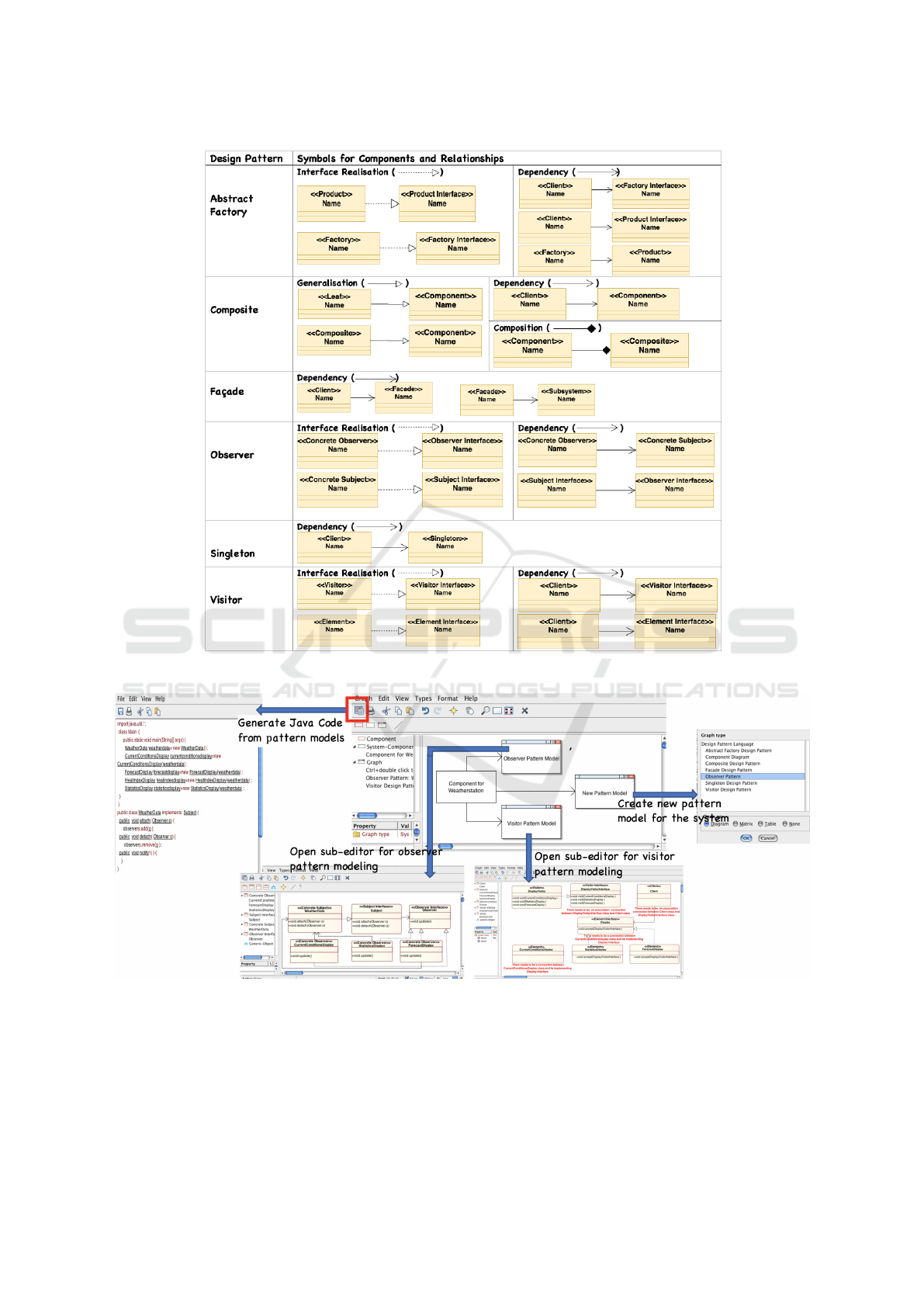
Figure 1: DesPat’s notation set.
Figure 2: The modeling editor for DesPat.
which is depicted in Figure 2. So, for any software
system to be modeled, the system may be decom-
posed into components using simple boxes. Users
may link the component box with a set of boxes each
of which represents a different pattern model specifi-
cation for the design of that component. Whenever a
pattern model box is clicked, a list appears for choos-
ing the pattern type and then a new sub-editor opens
for drawing the pattern model using DesPat’s pattern-
specific notation set. Users may use the sub-editor to
ENASE 2021 - 16th International Conference on Evaluation of Novel Approaches to Software Engineering
254

Figure 3: Adding/removing element attributes/operations.
drag and drop the modeling elements of the pattern-
specific notation set and add/remove attributes/opera-
tions to the elements. As depicted in Figure 3, when-
ever users click on the element, a dialog box opens for
editing the element attributes and operations.
4.2 Model Analyser
We used Metaedit+’s constraint definition technology
to define the validation rules for each design pattern,
which are given in Figure 4. So, those rules can be
checked by the modeling editor at modeling time. As
depicted in Figure 2, users are warned with the red-
colored messages at modeling time, which indicates
the violation of those rules and give information about
what the error stems from. Moreover, we introduced
the rules that constrain the elements involved in each
design pattern to provide some required operations.
For instance, in the observer design pattern, a sub-
ject must provide the operations attach and detach,
and an observer must provide the operations update.
So, the modeling editor warns the users automatically
at modeling time when such operations are missing.
Similarly, if the visitor element in a visitor pattern
model has no visit operation, a warning is generated.
4.3 Code Generator
We used Metaedit+’s generator definition technology
and develop a Java code generator for the modeling
editor. Whenever the icon shown in Figure 2 that are
displayed on the modeling editor is clicked for any
project, a single Java file is generated that represent all
the pattern models specified in that project. Figure 5
depicts the translation from a visitor pattern model
to a Java program. The translated Java program in-
cludes a class/interface definition for each modeling
element specified in the pattern model - an interface
element transformed as a Java interface while other
elements as a Java class. Each Java class and inter-
face consists of the method definitions that the corre-
sponding modeling element includes. Moreover, the
relationships between the modeling elements such as
generalisation, interface realisation, and composition
are also translated accordingly. Note that some of the
class methods (e.g., the accept methods in the Fruit
and Book classes) are translated with their implemen-
tation, as the behaviours of those methods should
never change so as to meet the pattern goals. How-
ever, the user-added operations in the model elements
are translated into the class methods with empty im-
plementation (see the methods in the Book, Fruit,
and ShoppingCartVisitor classes). Likewise, the class
methods that correspond to the operations whose be-
haviours need to be implemented by the users (e.g.,
the visit method in the ShoppingCartVisitorImpl) are
left empty. Also, in the case where the same mod-
eling elements are re-used in multiple patterns (i.e.,
see the weather station example in Section 5), a sin-
gle Java class/interface is transformed that includes
the translations of the attributes, operations, and rela-
tionships from each pattern model which the element
is involved in. It should be noted that the Java code
transformed from the pattern models of any model-
ing project is not actually a complete (i.e., executable)
code. The transformed code represents mainly the
system structure that is modeled in terms of differ-
ent design pattern models including the classes, their
attributes and methods. However, one needs to im-
plement the method behaviours to reach a complete
code. Due to the limited space, the translation algo-
rithms can be found in the project web-site
1
.
To determine the quality of the transformed Java
code, we used the Sonarqube platform
2
. Sonarqube
allowed us to detect any code smells such as miss-
ing comments, unused variables, and wrong access
modifiers for variables. We made the necessary fixing
operations on the code generator and minimised the
code smells occurring in the transformed code from
the pattern model(s).
5 CASE-STUDIES
Now, we illustrate DesPat via some real-world appli-
cations that can be designed with the supported design
patterns. We used DesPat to draw the pattern models,
check correctness, and produce the Java code. The
full model specifications and the generated code are
accessible via the project web-site
1
.
To design the vending machine with many bever-
ages, we specified an abstract factory design pattern
model. As Figure 6 shows, two factory elements are
specified, one linked with the hot drink products (e.g.,
black coffee) and other linked with the cold drink
products (e.g., lemonade). Whenever the client re-
quests a beverage, the request is directed to the corre-
sponding factory via the factory interface. The factory
2
Sonarqube web-site: https://www.sonarqube.org/
DesPat: A Modeling Toolset for Designing and Implementing Software Systems using Design Patterns
255
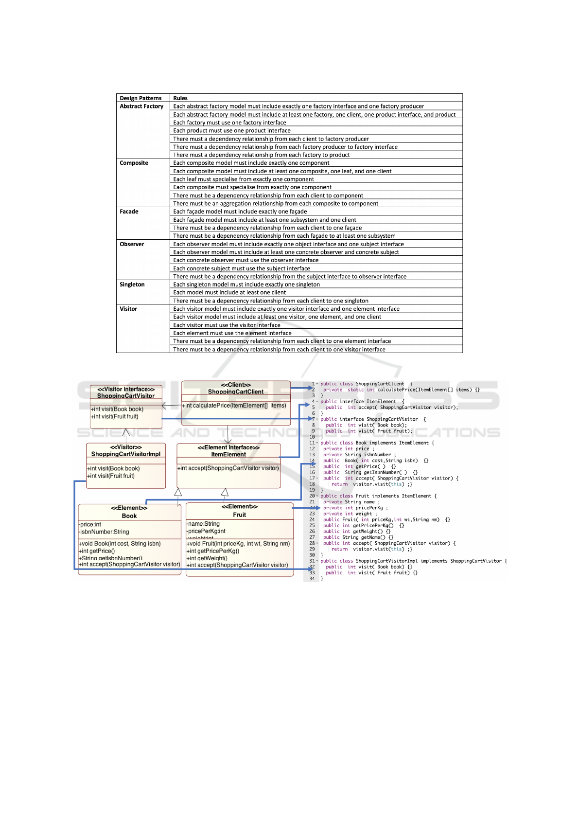
Figure 4: The validation rules for DesPat.
Figure 5: Transforming pattern model into Java code.
in question then creates the product.
To design the file directory system, we specified a
composite design pattern model. As Figure 7 shows,
the client sends a request to the file which is spe-
cialised by the text file (leaf) and the directory (com-
posite). Being composite, the directory may consist
of other files.
To design the video converter system that offers
services for video conversion, we specified a facade
design pattern model. As Figure 8 shows, the client
sends a request to the video converter that acts as a fa-
cade. The video converter facade is linked with differ-
ent sub-systems that each perform a video conversion
in a different format. The video converter facade di-
rects the request to the corresponding sub-system de-
pending on the service arguments passed by the client.
ENASE 2021 - 16th International Conference on Evaluation of Novel Approaches to Software Engineering
256
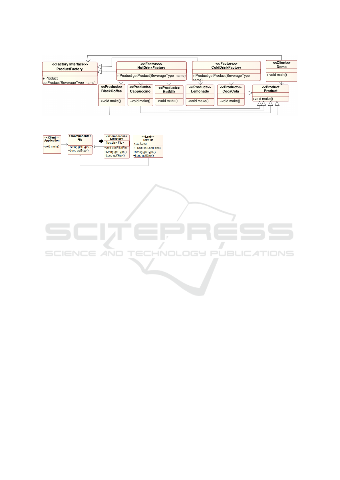
Figure 6: The abstract factory design pattern model for the vending machine system.
Figure 7: The composite design pattern model for the file
directory system.
Another case study is the weather station, where
the weather data are shared with the displaying
devices. We combined the observer and visitor
pattern models to design the weather station, as
shown in Figure 9 and and Figure 10 respectively.
The pattern models share the CurrentConditions-
Display, StatisticsDisplay, and ForecastDisplay ele-
ments, which play different roles in different pattern
models. While the three elements each play the ob-
server role in the observer pattern, they play the el-
ement role in the visitor pattern. Concerning the
observer pattern model, forecast-display, statistics-
display, and current-conditions-display are concrete
observers, which send requests to the weather data
subject to attach/detach themselves. The subject
may send a request to the observers attached via
their interfaces so as to update them whenever the
weather data change. Concerning the visitor pat-
tern model, forecast-display, statistics-display, and
current-conditions-display act as the elements that are
visited by DisplayVisitor which run the appropriate
display operation for each visited element.
We used the singleton design pattern to model a
printer sharing system where a single printer acts as
a singleton and shared by several client applications
(e.g., Word processor, PDF reader, etc.). As Fig-
ure 11 shows, different clients may send a request to
the same printer singleton.
We used the visitor design pattern to model a
shopping cart system. Here, any items can be sold
at any price where the price calculation operation ap-
plied to different items can be abstracted away from
the item specifications and dealt with by the visitor.
As Figure 12 shows, the shopping cart is specified
with two items (i.e., book and fruit). The client uses
the visitor interface to request from the visitor the
price calculation operation and then uses the item in-
terface to request the necessary item so as to get the
visitor operation to be executed on the requested item.
6 PRELIMINARY EVALUATION
We surveyed 6 final-year undergraduate CS students
to evaluate DesPat’s usefulness in practice. The stu-
dents have been selected from those who has taken
the software engineering course where the design pat-
terns are taught and passed the course with grade B or
above (in USA grading system). In our survey, we
considered the case-studies that we discussed in Sec-
tion 5 - i.e., vending machine, file directory, shopping
cart, printer sharing, video converter, and weather sta-
tion. Each student has been assigned one specific
case-study and asked to directly implement the solu-
tion in Java. The students have been given a period
of time to finish their tasks and then asked to provide
feedback. Once finished, the students have been asked
to use DesPat to perform model-based development
this time. Note that the students have already been
informed about which design pattern(s) is required to
be applied for each case-study.
After the students completed their tasks, we con-
ducted an interview with each student separately.
Concerning the first phase where solutions have been
implemented directly, we asked to learn (i) how long
it takes to have an executable implementation with
patterns, (ii) how the students ensure that the patterns
are applied correctly at code level, and (iii) any dif-
ficulties in applying the design patterns at code level.
Concerning the second phase, we asked to learn (i)
how easy it is to learn and use the language notation
set, (ii) how long it takes to create the pattern mod-
els, (iii) how easy it is to use the generated code from
models to obtain an executable implementation, (iv)
any difficulties in using the modeling language and
its toolset, (v) any suggestions on improving DesPat.
DesPat: A Modeling Toolset for Designing and Implementing Software Systems using Design Patterns
257
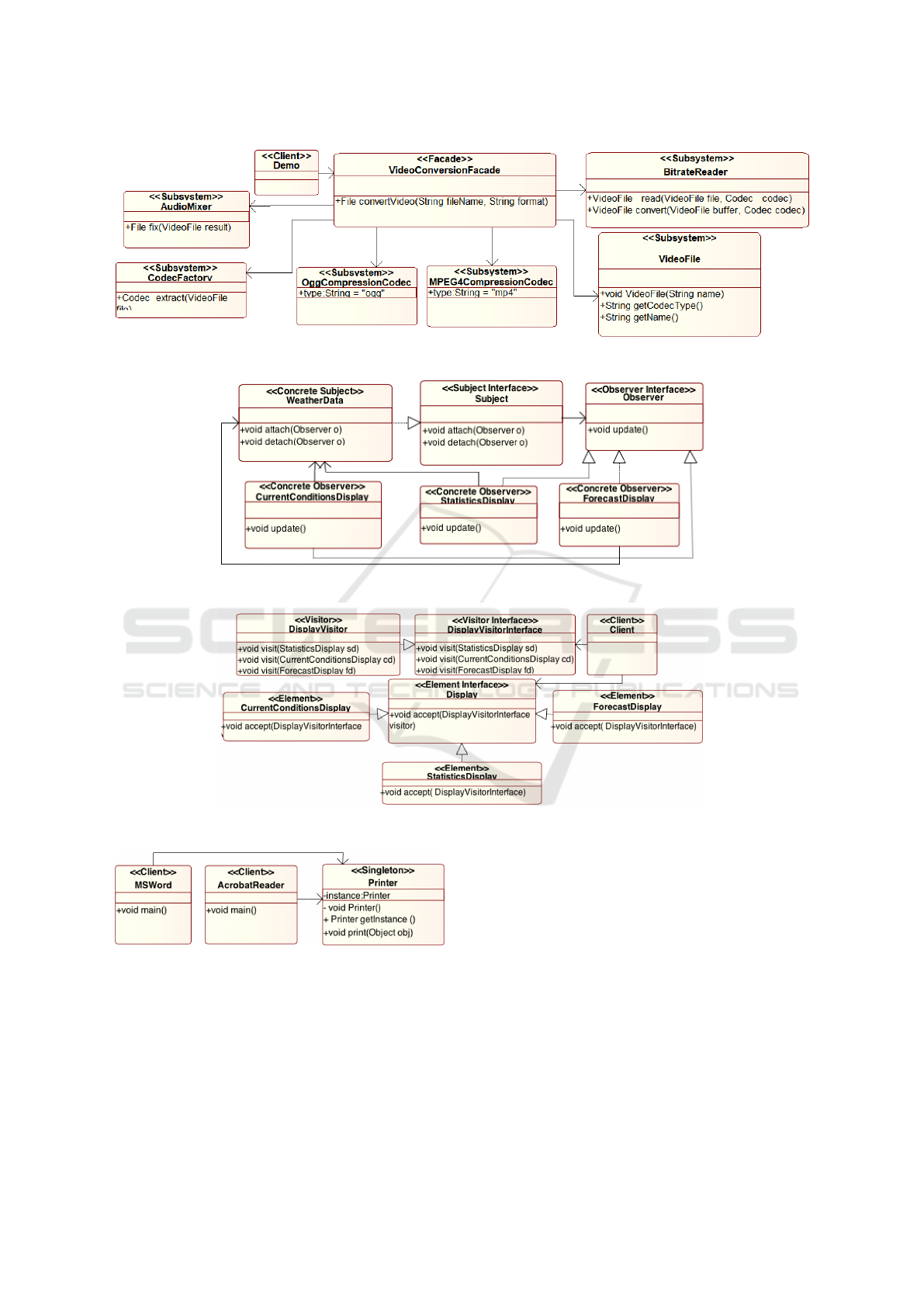
Figure 8: The facade design pattern model for video converter system.
Figure 9: The observer design pattern model for the weather station.
Figure 10: The visitor design pattern model for the weather station.
Figure 11: The singleton design pattern model for the
printer sharing system.
Table 1 shows (i) how much time the students spent
in documenting and implementing the case-studies
manually and (ii) the time they spent when they used
DesPat for modeling the pattern models for the case-
studies and obtaining code automatically. Note that
the time information given here are the approximate
times that the students stated themselves. So ap-
parently, using DesPat for each case-study consider-
ably reduces the time for obtaining the implementa-
tion of the case-study solutions. Note that modeling
the weather station system required relatively more
time as the weather station has been specified in terms
of the combinations of two pattern models (see Sec-
tion 5). According to the students’ feedback, this is
because the students who directly implemented the
solutions also needed to work out the system structure
firstly so as to determine the components and decide
on their relationships in accordance with the pattern
rules. The students either sketched their design on a
paper or used some modeling editors, which however
did not enable them to check the correctness of their
ENASE 2021 - 16th International Conference on Evaluation of Novel Approaches to Software Engineering
258
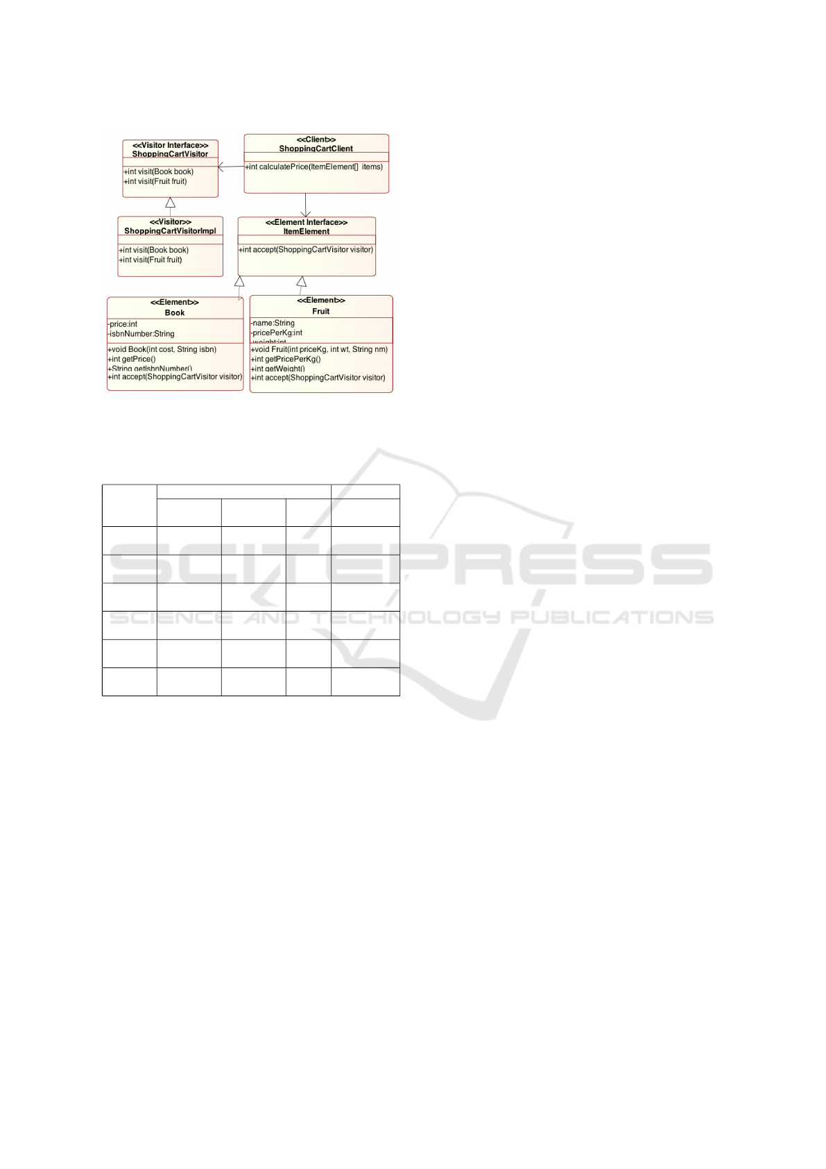
Figure 12: The visitor design pattern model for the shop-
ping cart system.
Table 1: The time spent by the students in developing the
case-studies (i) manually and (ii) by modeling with DesPat.
Case
Study
Without DesPat With DesPat
Documen-
tation Time
Implemen-
tation Time
Total
Time
Modeling
Time
File
Directory
1 hour 3 hours 4 hours 30 mins
Printer
Sharing
1 hour 2 hours 3 hours 17 mins
Shopping
Cart
1 hour 4 hours 5 hours 38 mins
Vending
Machine
1 hour 2 hours 3 hours 38 mins
Video
Converter
1 hour 2 hours 3 hours 20 mins
Weather
Station
1 hour 5 hours 6 hours 80 mins
models and generate code automatically. Another is-
sue pointed out here is having to manually check if the
implemented solution meets the pattern rules, which
required extra time and effort.
The students found DesPat’s notation set easy to
learn and use. Comparing DesPat with UML, the
students agreed that DesPat’s notation is similar to
UML’s class diagram which almost all software de-
velopers/engineers are familiar with. However, the
students also stated that UML’s class diagram is not
adequate for pattern-centric modeling, since UML
does not provide any particular syntax and semantic
for patterns and support such facilities as combining
patterns. Moreover, as also the students indicated, the
existing UML tools do not enable to specify UML
models for different patterns, check their correctness,
and produce the corresponding code either.
Concerning the quality of the generated code, the
students all agree that the generated code is easy to
use and modify given the comments supplementing
each snippet (e.g., methods and variables) and de-
scribing their purposes.
As the students also agreed, DesPat could be used
in the software engineering education so as to make
students gain the practical experience about design
patterns. Indeed, understanding the motivations and
benefits of design patterns (e.g., re-usability, modu-
larity, and high analysability) is quite difficult and any
tool such as DesPat that can aid in practicing about
design patterns would be so useful.
7 CONCLUSION
In this paper, we introduced a modeling toolset called
DesPat for designing software systems using Gamma
et al.’s six design patterns that are highly used in in-
dustry - i.e., the factory, composite, facade, observer,
singleton, and visitor design patterns. DesPat offers
for each supported design pattern a visual modeling
notation set that is inspired by UML’s class diagram.
That is, the components composing software systems
are specified using the class notation extended with
the appropriate stereotypes and the component rela-
tionships are specified with the relationships inherited
from UML such as generalisation, association, and in-
terface realisation. The pattern models are combined
by re-using the same component(s) in different pat-
tern models. DesPat’s modeling editor can be used for
specifying the pattern model(s) for any software sys-
tem to be designed and checking the pattern models
against the pattern rules at modeling time. DesPat’s
code generator may then produce Java code from the
pattern models specified for the software system. We
illustrated DesPat via a number of real-world applica-
tions, including the vending machine for the abstract
factory pattern, file directory for the composite pat-
tern, video converter for the factory pattern, weather
station for the observer pattern, printer sharing for the
singleton pattern, and online shopping cart for the vis-
itor pattern.
We are now extending DesPat with a new GUI
tool for enabling users to define their own patterns
that can be used via the existing modeling editor to
specify software models according to the user-defined
patterns and generate Java code. Also, we plan to
use more complex case-studies to evaluate our toolset
in the near future, in which multiple different pat-
terns can be combined including both GoF’s patterns
and some user-defined patterns. Another future im-
provement could be to do with improving the notation
DesPat: A Modeling Toolset for Designing and Implementing Software Systems using Design Patterns
259

set with the support for specifying the behavioural
design decisions. So, the behaviours of the opera-
tions that the components perform may be specified
with the well-known Design-by-Contract approach
(Meyer, 1992). Moreover, we could develop another
tool in the future, which can reverse engineer the Java
code to obtain the pattern-centric models in DesPat.
By doing so, one may check any Java code for their
conformance to design patterns.
ACKNOWLEDGEMENT
This work was supported by a project of the Scien-
tific and Technological Research Council of Turkey
(TUBITAK) under grant 120E144.
REFERENCES
Al-Obeidallah, M. G., Petridis, M., and Kapetanakis, S.
(2016). A survey on design pattern detection ap-
proaches. International Journal of Software Engineer-
ing (IJSE), 7(3):41–59.
Alexander, C. (1979). The Timeless Way of Building. Ox-
ford University Press.
Alexander, C., Ishikawa, S., Silverstein, M., Jacobson, M.,
Fiksdahl-King, I., and Angel, S. (1977). A Pattern
Language - Towns, Buildings, Construction. Oxford
University Press.
Dong, J., Zhao, Y., and Peng, T. (2009). A review of de-
sign pattern mining techniques. International Journal
of Software Engineering and Knowledge Engineering,
19(06):823–855.
Florijn, G., Meijers, M., and van Winsen, P. (1997). Tool
support for object-oriented patterns. In Aksit, M. and
Matsuoka, S., editors, ECOOP’97 - Object-Oriented
Programming, 11th European Conference, Jyv
¨
askyl
¨
a,
Finland, June 9-13, 1997, Proceedings, volume 1241
of Lecture Notes in Computer Science, pages 472–
495. Springer.
Gamma, E., Helm, R., Johnson, R., and Vlissides, J.
(1994). Design patterns: Elements of reusable object-
oriented software. Addison Wesley. ISBN-13: 978-
0201633610.
Hannemann, J. and Kiczales, G. (2002). Design pattern
implementation in java and aspectj. SIGPLAN Not.,
37(11):161–173.
Hedin, G. (1997). Language support for design patterns
using attribute extension. In Bosch, J. and Mitchell,
S., editors, Object-Oriented Technology, ECOOP’97
Workshop Reader, ECOOP’97 Workshops, Jyv
¨
askyl
¨
a,
Finland, June 9-13, 1997, volume 1357 of Lecture
Notes in Computer Science, pages 137–140. Springer.
Henninger, S. and Corr
ˆ
ea, V. (2007). Software pattern com-
munities: Current practices and challenges. In Pro-
ceedings of the 14th Conference on Pattern Languages
of Programs, PLOP ’07, New York, NY, USA. Asso-
ciation for Computing Machinery.
Kelly, S., Lyytinen, K., and Rossi, M. (2013). Metaedit+
A fully configurable multi-user and multi-tool CASE
and CAME environment. In Jr., J. A. B., Krogstie,
J., Pastor, O., Pernici, B., Rolland, C., and Sølvberg,
A., editors, Seminal Contributions to Information Sys-
tems Engineering, 25 Years of CAiSE, pages 109–129.
Springer.
Kim, D. (2015). Design pattern based model transformation
with tool support. Softw. Pract. Exp., 45(4):473–499.
Mak, J. K. H., Choy, C. S. T., and Lun, D. P. K. (2004).
Precise modeling of design patterns in uml. In Pro-
ceedings. 26th International Conference on Software
Engineering, pages 252–261.
Malavolta, I., Lago, P., Muccini, H., Pelliccione, P., and
Tang, A. (2012). What industry needs from architec-
tural languages: A survey. IEEE Transactions on Soft-
ware Engineering, 99.
Mapelsden, D., Hosking, J., and Grundy, J. (2002). De-
sign pattern modelling and instantiation using dpml.
In Proceedings of the Fortieth International Confer-
ence on Tools Pacific: Objects for Internet, Mobile
and Embedded Applications, CRPIT ’02, page 3–11,
AUS. Australian Computer Society, Inc.
Meyer, B. (1992). Applying “Design by Contract”. IEEE
Computer, 25(10):40–51.
Mikkonen, T. (1998). Formalizing design patterns. In Torii,
K., Futatsugi, K., and Kemmerer, R. A., editors, Forg-
ing New Links, Proceedings of the 1998 International
Conference on Software Engineering, ICSE 98, Kyoto,
Japan, April 19-25, 1998, pages 115–124. IEEE Com-
puter Society.
Nicholson, J., Gasparis, E., Eden, A. H., and Kazman, R.
(2009). Verification of design patterns with lepus3.
In Denney, E., Giannakopoulou, D., and Pasareanu,
C. S., editors, First NASA Formal Methods Symposium
- NFM 2009, Moffett Field, California, USA, April
6-8, 2009, volume NASA/CP-2009-215407 of NASA
Conference Proceedings, pages 76–85.
Ozkaya, M. (2018a). Analysing uml-based software mod-
elling languages. Journal of Aeronautics and Space
Technologies, 11(2):119–134.
Ozkaya, M. (2018b). The analysis of architectural lan-
guages for the needs of practitioners. Softw., Pract.
Exper., 48(5):985–1018.
Ozkaya, M. (2018c). Do the informal & formal software
modeling notations satisfy practitioners for software
architecture modeling? Information & Software Tech-
nology, 95:15–33.
Ozkaya, M. (2019). Are the UML modelling tools power-
ful enough for practitioners? A literature review. IET
Softw., 13(5):338–354.
Saeki, M. (2000). Behavioral specification of GOF design
patterns with LOTOS. In 7th Asia-Pacific Software
Engineering Conference (APSEC 2000), 5-8 Decem-
ber 2000, Singapore, pages 408–415. IEEE Computer
Society.
Taibi, T. and Ling, D. N. C. (2003). Formal specification
of design pattern combination using BPSL. Inf. Softw.
Technol., 45(3):157–170.
Zhang, C. and Budgen, D. (2013). A survey of experienced
user perceptions about software design patterns. Inf.
Softw. Technol., 55(5):822–835.
ENASE 2021 - 16th International Conference on Evaluation of Novel Approaches to Software Engineering
260
