
P2P Frames: Pattern-based Characterization of Functional
Requirements for Peer-to-peer Systems
Lirijan Sabani
a
, Roman Wirtz
b
and Maritta Heisel
Working Group Software Engineering, University of Duisburg - Essen, Oststr. 99, 47057 Duisburg, Germany
Keywords:
Requirements Engineering, Peer-to-peer Systems, Frames, Pattern, Functional Requirements.
Abstract:
Peer-to-peer systems have become an essential element of computer networks and represent a special category
of distributed systems. The strong decentralization as well as the scalability and fault tolerance are only
some of the reasons why many companies have adopted this technology. Peer-to-peer systems consist of
different subsystems, connected by a network. The decomposition into these subsystems requires a detailed
analysis and documentation of functional requirements, which is a challenging task. In previous work, we
proposed a method based on Jackson’s problem frames approach that allows for modeling and documenting
of functional requirements for distributed systems. To render knowledge about requirements for distributed
systems reusable, we developed patterns as an extension for problem frames. However, these patterns (so-
called frames) do not capture the specific characteristics of peer-to-peer systems. We thus analyzed typical
requirements of peer-to-peer systems and observed several frames specific to peer-to-peer functionalities. We
call these frames P2P frames. In this paper, we present frames for bootstrapping, query routing in unstructured
networks, and the data transfer process in such systems. We also present our pattern system for requirements
engineering, consisting of problem frames and frames for distributed systems, which helps software engineers
to select suitable frames.
1 INTRODUCTION
In recent years, peer-to-peer (P2P) applications have
become popular with millions of users and have been
realized in various versions. In contrast to traditional
distributed systems, a P2P system involves interac-
tion between many subsystems (i.e., the peers). Peers
can simultaneously assume the role of a client and
server and run on different platforms, thus creating
a decentralized network. P2P systems can be divided
into two fundamentally different types: structured and
unstructured. Structured P2P systems organize their
peers in a structured graph and use indexes. These
indexes enable the allocation of resources and peers.
In most cases, this allocation is achieved by using
a distributed hash table. Unstructured P2P systems
have no global structure and establish connections be-
tween peers arbitrarily. The peers do not have access
to any information about the resources available to
their neighbors. Typical use cases for P2P applica-
tions range from filesharing services such as Gnutella
to cryptocurrencies (e.g., Bitcoin). The functionali-
a
https://orcid.org/0000-0003-0381-4643
b
https://orcid.org/0000-0003-3260-4362
ties of the different peers highly depend on each other,
even though the subsystems are deployed on differ-
ent hardware and operating systems. Therefore, it
is not sufficient to consider a subsystem in isolation;
rather, it is necessary to analyze a P2P system as a
whole. Identifying the complex functionalities each
peer must provide is a challenge for software engi-
neers.
We aim to support software engineers from the
beginning of a software development process (i.e.,
during requirements engineering). By following a
pattern-based approach, we provide a systematic way
to analyze and document functional requirements for
P2P systems. In previous work, we proposed a
method to document functional requirements for dis-
tributed systems (Wirtz et al., 2020) based on Jack-
son’s problem frames. A problem frame is a pattern
for a common problem during software development
(i.e., a functional requirement). We extended Jack-
son’s notation with elements for modeling the charac-
teristics of distributed systems. Furthermore, we pro-
posed an initial set of frames for distributed systems
that capture typical distributed functionalities. How-
ever, the new frames are not specifically designed to
Sabani, L., Wirtz, R. and Heisel, M.
P2P Frames: Pattern-based Characterization of Functional Requirements for Peer-to-peer Systems.
DOI: 10.5220/0010434702390250
In Proceedings of the 16th International Conference on Evaluation of Novel Approaches to Software Engineering (ENASE 2021), pages 239-250
ISBN: 978-989-758-508-1
Copyright
c
2021 by SCITEPRESS – Science and Technology Publications, Lda. All rights reserved
239

meet the precise characteristics of P2P systems. In-
stead, they consider distributed systems in general.
In this paper, we refined the frames for this type of
software systems. We began by identifying core func-
tionalities of P2P systems (see Table 1). The boot-
strapping mechanism is an essential task in P2P sys-
tems (Knoll et al., 2008; Boldt et al., 2017). The aim
is to find an entry point into the P2P system to inte-
grate a new peer. When a new peer wants to join a
P2P system, the IP address and port of a peer that is
currently connected to the desired P2P system must
be discovered. Query routing among peers is also a
key functionality for the correct operation of a P2P
system, without which resource sharing would not be
possible (Buford et al., 2008; Dinger, 2009). In this
paper, we consider query routing in a decentralized
and unstructured P2P model. In addition to bootstrap-
ping and query routing, data transfer at the content
level is also an essential requirement of P2P systems.
The transfer of files is based on the information where
the files are located.
For these functionalities, we identified a set of
frames, each which describes a typical functional re-
quirement in that context. We call these frames P2P
Frames, which we describe in a consistent manner
with a template. Each description consists of frame
diagrams for the sender and the receiver, textual pat-
terns for the functional requirement, and a set of
known uses. Our second contribution is a frame li-
brary system that helps engineers to systematically
identify suitable frames for their specific problem.
Using a tree structure, our frame library system sys-
tematically describes the hierarchy between different
frames, which allows one to structure the frame li-
brary. By adding newly identified frames to the frame
library system, engineers can improve the library and
adapt it to their own needs.
The remainder of the paper is structured as fol-
lows. In Section 2, we introduce Jackson’s prob-
lem frames approach and our extension for distributed
systems as background knowledge. Section 3 intro-
duces our new set of so-called P2P frames for the
mentioned requirements. In Section 4 we present an
overview of our frame library system and describe
how it can be integrated into a requirements engineer-
ing process. Using a small case study, we illustrate the
application of our P2P frames in Section 5. We dis-
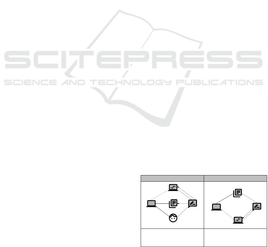
Table 1: Functionalities of P2P systems.
Name Problem
Bootstrapping How can peers join the overlay network?
Query routing How can peers query information in an un-
structured overlay network?
Data transfer How can peers transfer data?
cuss related work in Section 6 and conclude the paper
in Section 7 with a brief summary and an outlook on
future research directions.
2 BACKGROUND
In this section, we introduce the basic concepts, no-
tations, and terms that are necessary for further un-
derstanding. First, we introduce the concept of Jack-
son’s problem frames (Jackson, 2000). Second, we
describe our previous work on requirements engineer-
ing for distributed systems.
2.1 Problem Frames
For modeling functional requirements, we use the
problem frames approach introduced by Jackson
(Jackson, 2000). A problem frame is a pattern that
classifies a typical software development problem
(i.e., a functional requirement).
Jackson distinguishes between context diagrams
and problem diagrams. The environment in which the
machine (that is, the software to be developed) is op-
erated can be represented by a context diagram (Jack-
son, 2000). The context diagram indicates where the
problem is located and which domains it concerns.
This diagram also displays who has control over the
common phenomena. A context diagram, therefore,
forms the basis for problem decomposition by pro-
jection. A problem diagram describes a concrete re-
quirement and is an instance of a problem frame. The
basic notation for such diagrams consists of domains,
phenomena, and interfaces.
Jackson also distinguishes between two types of
domains: machine domains and problem domains.
Machine domains (represented by the symbol ) rep-
resent the software to be developed. Problem domains
represent entities of the real world that are relevant for
that problem. There are different types of these do-
mains: a biddable domain (represented by the symbol
) represents an entity with an unpredictable behav-
ior (e.g., humans). A causal domain (represented by
the symbol ) represents mechanical or electrical de-
vices whose actions and reactions are predictable. A
lexical domain (represented by the symbol ) is used
for data representation. To model a connection be-
tween two other domains (e.g., via technical devices),
a connection domain (represented by the symbol )
can be used.
Domains are connected via interfaces that are rep-
resented by solid lines. These interfaces consist of
phenomena. Symbolic phenomena represent a type
ENASE 2021 - 16th International Conference on Evaluation of Novel Approaches to Software Engineering
240
P!{enterProject}
W!{confirmRepresentation}
enterProject
Webpage
Person
Enter Project
Projectinformation
Software
confirmRepresentation
confirmProjectS!{makingProject}
W!{createProject}
S!{showConfirmEnter}
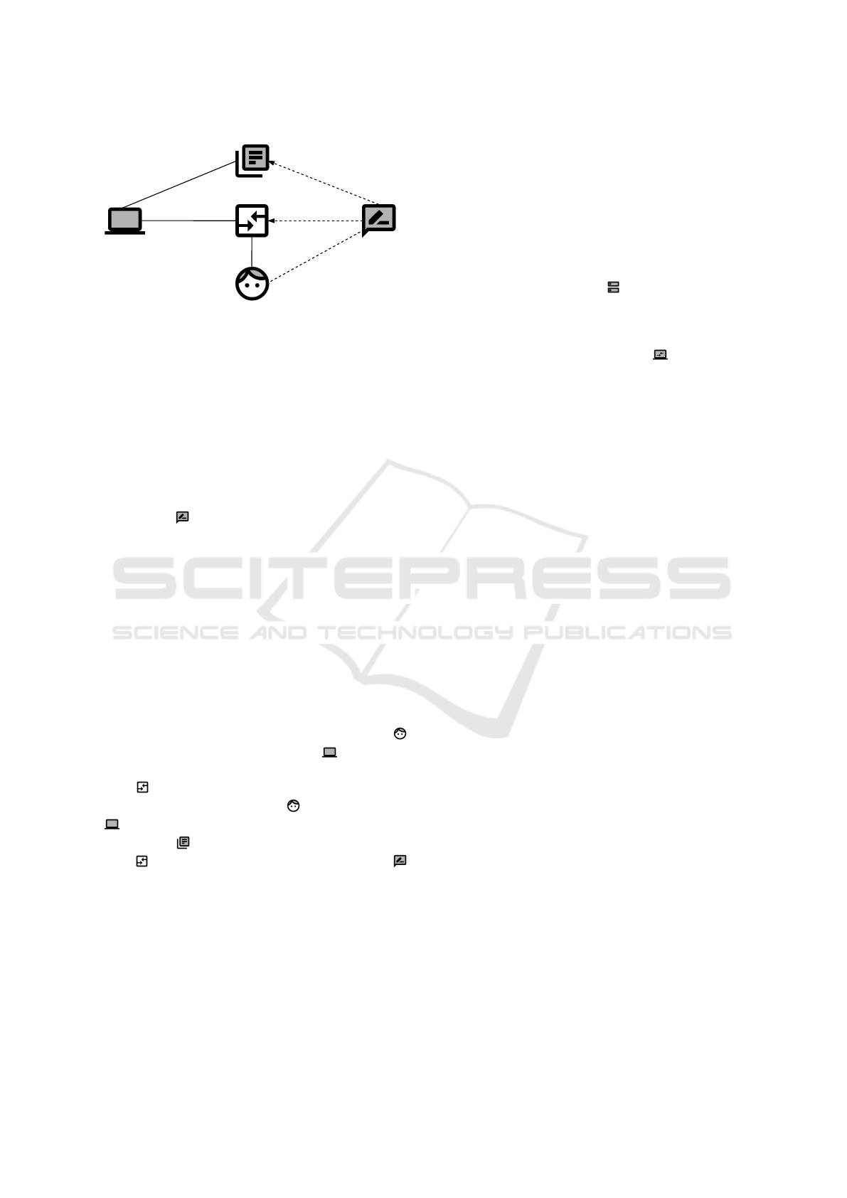
Figure 1: Example of a problem diagram.
of information or a state, while causal phenomena
describe commands, actions and events. Each phe-
nomenon is controlled by exactly one domain and can
be observed by other domains. A phenomenon that is
controlled by one domain and observed by another is
called a shared phenomenon. An interface contains a
set D!{...} of shared phenomena, where D is an ab-
breviation for the controlling domain.
In addition to domains and interfaces, a prob-
lem diagram contains a requirement (represented by
the symbol ) that is an optative statement. This
statement describes how the environment will behave
when the machine has been integrated. A requirement
refers to an arbitrary number of phenomena. This
is represented by a dashed line between the require-
ment and the controlling domain of the phenomenon
to which the requirement refers. To describe the de-
sired behavior of the environment, the requirement
constrains at least one phenomenon. This constraint
is represented by a dashed line with a filled arrow-
head pointing from the requirement to the controlling
domain.
Figure 1 is an example of a diagram for a func-
tional requirement for creating a project. A Person
provides information to the Software by entering
all the necessary data to create a project. The Web-
page represents the connection domain and serves
as a link between the Person and the Software
. The data is then stored in the database Project-
Information and feedback is received via the Web-
page . The functional requirement Enter Project
refers to the phenomenon enterProject and constrains
the phenomenon confirmRepresentation and confirm-
Project.
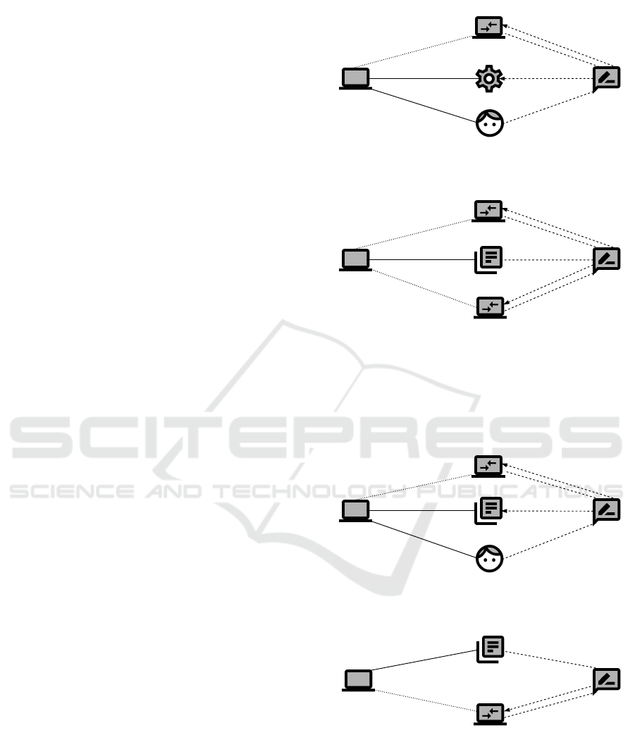
2.2 Frames for Distributed Systems
In previous work, we extended Jackson’s problem
frames for an application in the context of distributed
systems (Wirtz et al., 2020). In contrast to a prob-
lem frame, our approach considers not only a sin-
gle system but also different subsystems. Therefore,
each distributed frame consists of one diagram for the
sender side and another for the receiver side.
2.2.1 Extended Notation
To analyze distributed systems, we introduce two new
domain types. The domain type Distributed System
(represented by the symbol ) consists of at least
two machine domains and covers all subsystems to be
developed. To model the relation between the differ-
ent subsystems, we introduce the domain type Remote
Machine (represented by the symbol ). By adding
this domain to the diagram, we represent an interac-
tion with another subsystem. The interface from a
machine to a remote machine is a special one that we
call Remote Interface (represented by a dotted line).
Since the interaction between subsystems occurs via
a network, the connection is considered unreliable.
To specify the interfaces between the domains
more precisely in problem diagrams, the interfaces
contain an attribute derived from the attack vec-
tor of the Common Vulnerability Scoring System
(FIRST.org, 2019). The attribute can have one of the
following four values: (i) Network (N) describes re-
mote connections over different networks (e.g., via
the Internet), (ii) Adjacent (A) represents local net-
work connections, (iii) local (L) denotes access to do-
mains that are not connected to the Internet, and (iv)
physical (P) describes the physical connection to do-
mains. A connection between a machine and a remote
machine is either network or adjacent. A requirement
can also be distributed. Distributed requirements are
introduced to describe functional requirements that
affect different subsystems.
2.2.2 Description Format
To specify frames for distributed systems in a consis-
tent way, we provide a template (see Table 2 for an
overview). The template consists of some basic infor-
mation and a frame description.
Basic Information. We provide a short informal de-
scription that summarizes the frame and briefly de-
scribes the context for which it is applicable. The
textual description of the functional requirement to
be satisfied by the distributed system is also part of
the informal description. The requirement will later
be decomposed for the involved subsystems. In addi-
tion, we list typical examples of scenarios as known
uses for the application of the frame.
Frame Description. We distinguish between the
sender side and the receiver side. Since our approach
is applicable for any type of distributed system, we do
P2P Frames: Pattern-based Characterization of Functional Requirements for Peer-to-peer Systems
241
not use the notion of client/server side here. We pro-
vide a frame diagram for each side. A frame diagram
contains the domain types, connecting interfaces, and
requirement references for the frame. By instantiat-
ing the frame diagram in the concrete context, one can
create a problem diagram. In addition to the frame di-
agram, we propose a textual pattern that describes the
functional requirement in natural language. The no-
tation “h...i” indicates a variable in the textual pattern
that needs to be instantiated.
In the following sections, we use the template to
specify our P2P frames.
2.2.3 Frame Overview
For distributed systems, we have identified seven
frames. These frames are derived from problem
frames (Jackson, 2000; Choppy and Heisel, 2004),
and the abbreviation DF indicates a frame related to
distributed systems.
Required Behavior (DF): One subsystem can con-
trol domains of its physical environment, and an-
other subsystem can issue commands to control
these domains. The task is to create a distributed
system in which one subsystem’s machine can re-
motely control domains in the physical environ-
ment of another subsystem.
Commanded Behavior (DF): A subsystem can con-
trol domains of its physical environment, and
users can issue commands through another sub-
system to control these domains. The task is to
create a distributed system in which a user can re-
motely control domains in the physical environ-
ment of another subsystem.
Information Display (DF): One subsystem continu-
Table 2: Frames for distributed systems – Description for-
mat.
Basic Information
Name Short and descriptive name for the frame.
Description Short informal description about the frame
and the context for which it is applicable.
Known uses List of typical examples where the pattern can
be applied.
Frame Description
Sender
Frame diagram Diagram that contains the relevant domains
and interfaces on the sender side.
Textual pattern Textual pattern for the relevant part of the
functional requirement on the sender side.
Receiver
Frame diagram Diagram that contains the relevant domains
and interfaces on the receiver side.
Textual pattern Textual pattern for the relevant part of the
functional requirement on the receiver side.
ously receives information from the physical en-
vironment, and another subsystem has a display
in its environment. The task is to exchange and
display the received information between the sub-
systems.
Simple Workpieces (DF): A user can use a subsys-
tem to edit some data, which can then be remotely
accessed on another subsystem. The task is to
transfer the commands to the subsystem where the
data is available and to manipulate the data ac-
cordingly.
Transformation (DF): A subsystem’s data are trans-
formed. For the transformation of the data, an-
other subsystem has to be used. The task is to
develop a system to transfer data from one system
to another to transform it. Then the transformed
data is stored in the subsystem from which it orig-
inates.
Query (DF): A user can retrieve some information
from a remote resource. The task is to develop a
system to query that data from another subsystem
and provide them to the user.
Update (DF): A user can modify some information
that is available at a remote resource. The task is
to develop a system to transfer the commands to
modify the data to the subsystem and to provide
an appropriate feedback to the user.
However, these frames for distributed systems do not
capture specific characteristics of P2P systems. In
Section 3, we describe frames particular to the identi-
fied core functionalities of P2P systems.
3 P2P FRAMES
In this section, we refine the frames for distributed
systems (see Section 2.2) and propose P2P Frames to
characterize specific problems that occur in the con-
text of P2P systems. Each P2P frame is a special kind
of frame for distributed systems and captures a spe-
cific functionality for a P2P system. Table 3 contains
the name of each P2P frame and the domain types that
are constrained and referred to on the sender and re-
ceiver side.
To consistently specify our P2P frames, we use
the template that we described in Section 2.2.2. In
the following sections, we present four P2P frames.
First, we describe two frames for bootstrapping mech-
anisms. Then we outline a query routing frame, fol-
lowed by a frame for transferring data.
ENASE 2021 - 16th International Conference on Evaluation of Novel Approaches to Software Engineering
242
3.1 Bootstrapping Frames
There are two classes of approaches for bootstrap-
ping, namely peer-based approaches and mediator-
based approaches (Knoll et al., 2008).
In the peer-based approach, peers can be discov-
ered in the network by contacting known peers di-
rectly. Peer caches are a well-known example of this
approach. A peer cache is a database of previously
known peers. It is part of the P2P application’s down-
load file and is updated when a peer connects to the
network. When a peer wants to join an existing net-
work, it tries to contact one of the peers in its peer
cache. If the contacted peer is available, it can be used
as an entry point into the network (Knoll et al., 2008).
In the mediator-based approach, a well-known en-
try point, the mediator, is used to find other peers in
the network. For example, mediators can be super-
peers of the network or hosts provided by the opera-
tor of the P2P system. When a peer wants to join an
existing network, it first contacts the mediator, which
then returns connection information from peers that
are currently active. A well-known example of this
approach is a rendezvous server. A rendezvous server
is a central server to which a joining peer can con-
nect. This server returns a list of already participating
peers.
We present our identified frames, Bootstrap-
ping Peer-based Approach (DF) and Bootstrapping
Mediator-based Approach (DF) in the following.
Since P2P systems are a subset of distributed systems,
we mark them with DF in the same manner as frames
for distributed systems (see Section 2.2).
Bootstrapping Peer-based Approach (DF).
Description. A peer wants to join the overlay net-
work. To join the network, a peer can use its peer
cache to contact another peer in the network directly,
without first contacting a mediator. The task is to de-
velop a peer-based (peer cache) bootstrapping mech-
anism that allows a peer to join the network.
Known Uses:
• Most Gnutella clients have their own internal peer
Table 3: P2P Frames – Overview.
ReceiverSender
Name
Domaintypes
referredto
Domaintypes
constrained
Domaintypes
referredto
Domaintypes
constrained
P2PFrames
BootstrappingPeer-based
Approach(DF)
RM RM RM,L
B,RM
B,RM
B,RM
RM
RM,C
RM,L
RM,L
RM,L
RM,L
RM,L
RM
RM
BootstrappingMediator-based
Approach(DF)
QueryRouting(DF)
Transfer(DF)
B,L,RM
Legend: C – causal, L – lexical, B – biddable, RM – remote machine
cache that stores IP addresses that were active
when the client was last used.
• eMule also uses the peer-based bootstrapping
strategy. Each peer has a cache list of servers.
Frame Description. Table 4 depicts the frame de-
scription for the frame Bootstrapping Peer-based Ap-
proach (DF).
On the sender side, the User initiates the connec-
tion between Peer A and Peer B with the event E1.
Using information Y1 from the Peer Cache, Peer A
connects to Peer B with the command C2. Peer B
confirms a successful connection with the command
C3.
On the receiver side, Peer B receives the connec-
tion request from Peer A and confirms the connection
(commands C2 and C3). Peer B updates the Remote
Cache’s information Y2 with the command C4.
Bootstrapping Mediator-based Approach (DF).
Description. A peer wants to join the overlay net-
work. To join the network, a mediator must be re-
quested to provide a list of the peers in the network.
The requesting peer then contacts one of the peers
from the list. The task is to develop a mediator-based
bootstrapping mechanism that allows a peer to join
the network.
Known Uses:
• Gnutella also implements a distributed ren-
dezvous server model called GWebCache, which
is a web-based caching system that allows a client
to request a list of online peers. In contrast to a
peer-based approach, a rendezvous server works
as a mediator to provide the list of known peers.
• Napster uses a directory service to find other peers
in the network. The addresses of the central
servers are hard-coded in the Napster client.
Frame Description. Table 5 depicts the frame de-
scription for the frame Bootstrapping Mediator-based
Table 4: Frame description for Bootstrapping Peer-based
Approach (DF).
Sender Receiver
Peer A
Peer B
PA!C1
PC!Y1
PA!C2
PB!C3
Y1
C3
C4
Peer Cache
User
E1U!E1
FR Sender
Peer A
Peer B
C2
PA!C2
PB!C3
C3
Remote Cache
Y2
RC!Y3
PB!C4
FR Receiver
A hUseri can request to join a net-
work by connecting to hPeer Bi
using the peer descriptors from
hPeer Cachei.
hPeer Ai can establish a connec-
tion, and the hRemote Cachei can
be updated with the correspond-
ing information.
P2P Frames: Pattern-based Characterization of Functional Requirements for Peer-to-peer Systems
243
Approach (DF).
On the sender side, a User can initiate the event
E1 at Peer A. Peer A then connects to the Mediator
with the command C1 and receives the list of peer
descriptors via command C2. Using this descriptor
information, Peer A connects to Peer B with command
C4. Peer B confirms the connection with command
C5.
For the receiver side, we present two diagrams.
The first describes the requirement for the mediator.
Peer A connects to the Mediator with C1. The Me-
diator retrieves a List of Peer Descriptors (informa-
tion Y1) with the command C3 and returns it to Peer
A. The second diagram describes the requirement for
joining the network by connecting to a peer. Peer A
can connect to Peer B, and Peer B confirms the con-
nection (commands C4 and C5). Furthermore, Peer
B updates the information Y2 of known peers at the
Remote Cache with the command C6.
3.2 Query Routing Frame
In unstructured P2P systems, query routing is a chal-
lenging task. Unlike in structured P2P systems, there
is no global directory containing data location infor-
mation, and peers are connected arbitrarily. We focus
on unstructured P2P systems in the following.
Each peer usually keeps a list of known peers (Bu-
ford et al., 2008), which are called neighbors. Mes-
sages can be exchanged with other peers in the neigh-
bor list as soon as a peer is connected to the overlay
network. An important message type is Query, which
queries specific resources. The query includes search
criteria such as the file name or certain keywords. It
is not known which peers in the overlay network have
Table 5: Frame description for Bootstrapping Mediator-
based Approach (DF).
Sender Receiver
FR Sender
Peer A
Peer B
PA!C1
M!C2
PA!C4
PB!C5
C3
C5
C6
Mediator
C2
User
E1U!E1
Peer A
Mediator FR Receiver
List of Peer
Descriptors
Y1
PA!C1
M!C2
C4
C1
LPD!Y1
M!C3
hPeer Ai can request a hList of
Peer Descriptorsi.
A hUseri can request a list of
peers from the hMediatori to
connect to hPeer Bi.
Peer A
Peer B FR Receiver
Remote Cache
Y2
PA!C4
PB!C5
C5
C4
RC!Y3
PB!C6
hPeer Ai can establish a connec-
tion, and the hRemote Cachei
can be updated with the corre-
sponding information.
the queried information. Therefore, a query can be
sent to any known peer. If these neighbors do not
have the information, they can forward the query to
their neighbors, and so on.
Unstructured P2P systems typically use a local
index-based search (Dinger, 2009). Each peer stores
the directory of its own data objects locally. When a
peer generates a query, it passes the query to peers
in the network to locate the desired object. Our
identified frame Query Routing (DF) is discussed
below.
Query Routing (DF).
Description. A user wants to use a resource in the
network and sends a query to one or more neighboring
peers. When a neighbor receives a query message,
it checks whether the requested file matches one of
the files in its directory of shareable files. If there
is a match, the neighbor returns a query hit message
to the requesting peer. The requested information is
displayed to the user. Each query hit message follows
the reverse path of the query message. If there is no
match, a peer forwards the query to its own neighbors
recursively until the requested information is found.
The task is to develop a routing mechanism.
Known Uses:
• Resource localization processes in P2P systems.
• An information request via a network.
Frame Description. Table 6 depicts the frame de-
scription for the frame Query Routing (DF).
On the sender side, a Query Initiator can initiate
the event E1 on Peer A for requesting a resource. Peer
A can forward the request to Peer B (command C1),
and Peer B returns the resource via the command C2.
Using the Display, Peer A can initiate the event E2 to
display the resource.
On the receiver side, Peer B can receive the re-
quest from Peer A (command C1). If it is available,
Peer B can retrieve the requested resource Y1 from the
Table 6: Frame description for Query Routing (DF).
Sender Receiver
FR SenderPeer A
Peer B
PA!E2 Y2
C2
C3,C4
Display
Query Initiator
E1QI!E1
PA!C1
PB!C2
FR ReceiverPeer B
Peer X
PB!C3
RDX!Y1
Y1
C5
C6
PX!C5
PB!C4
Peer A
PA!C1
PB!C2
C1
E2
Remote
Directory
A hQuery Initiatori can request
a resource from hPeer Bi to be
shown at the hDisplayi.
hPeer Ai can request a resource.
It can either be taken from the
hRemote Directoryi, or the re-
quest is forwarded to another
hPeer Xi.
ENASE 2021 - 16th International Conference on Evaluation of Novel Approaches to Software Engineering
244
Remote Directory using the command C3. If the re-
source is not available, Peer B forwards the request to
another peer, Peer X (command C4). Peer X works in
the same way as Peer B and will return the resource
with the command C5. Finally, Peer B returns the re-
source to the initial Peer A (command C2).
3.3 Transfer Frame
P2P technologies are usually a simple approach for
direct data transfer if one has the contact information
of the peer with the queried data. A direct connection
is established between them. Therefore, the protocols
that access a resource are usually independent of
the routing protocol. Well-known protocols like the
HTTP protocol are used (Hauswirth and Dustdar,
2005). With this method, almost all kinds of digital
media can be shared. Our identified frame Transfer
(DF) is discussed below.
Transfer (DF).
Description. A user requests data from another sub-
system. The requested data is stored on the user’s
storage device.
Known Uses:
• The use of resources in P2P systems.
• Downloading a file from a network.
Frame Description. Table 7 depicts the frame de-
scription for the frame Transfer (DF).
On the sender side, the Transfer Initiator can ini-
tiate the event E1 to transfer a file from Peer B to a
Local File. Peer A forwards the request to Peer B with
the command C1. Peer B then returns the file with the
command C2, and Peer A stores the file at Local File
with the command C4.
On the receiver side, Peer B receives the request
from Peer A with the command C1. With the com-
mand C3, Peer B retrieves the Remote File (phe-
nomenon Y1). Finally, Peer B returns the file to Peer
A with the command C2.
In the next section, we present a frame library in
which we integrate our P2P frames.
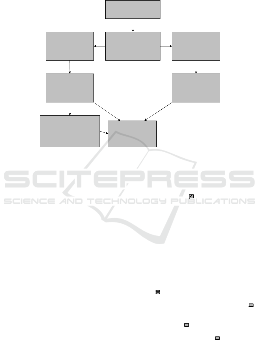
4 FRAME LIBRARY SYSTEM
To support the selection of suitable frames, we present
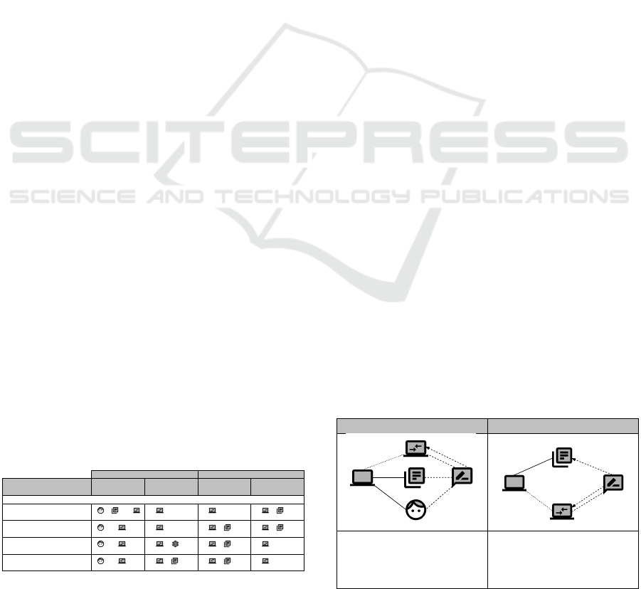
our frame library system. Figure 2 depicts the hierar-
chal order in which it is organized. Our system can be
integrated into a requirements engineering process to
document functional requirements of software.
The root element is the Frame Library, which is
a collection of suitable frames that are sorted by the
type of system for which the frames are applicable.
The starting point for selecting a suitable frame is
the set of functional requirements, which are repre-
sented in natural language. Our frame library system
assists engineers in selecting a suitable frame for each
of these requirements. For each requirement, it is nec-
essary to denote the appropriate type. We distinguish
between non-distributed requirements and distributed
requirements. A requirement that concerns at least
two subsystems is considered distributed, and a re-
quirement that concerns only one subsystem is non-
distributed.
Depending on the type of requirement that is spec-
ified, our frame library system offers a subset of avail-
able frames. The category of distributed frames con-
tains the basic frames specified for distributed sys-
tems (see Section 2.2), and the category problem
frames contains a set of frames (e.g., (Jackson, 2000;
Choppy and Heisel, 2004)) for non-distributed sys-
tems. If the distributed frames are not precise enough
for a problem, requirements engineers can also select
frames for special categories of distributed systems,
for example, our P2P frames for P2P systems. These
frames capture specific characteristics of system cat-
egories and are specifically adapted to them.
To ultimately determine whether a frame is ap-
plicable, engineers can compare the functional re-
quirement with the frame description we provide with
our template. If no suitable frame or combination of
frames exists, the problem must be decomposed into
smaller parts, or a new frame has potentially been
identified. The new identified frame can then be doc-
umented in the frame library using the frame descrip-
tion template from Section 2.2.2. The template con-
stitutes the foundation for the frame library. Using our
description format, requirements engineers can easily
specify their own distributed frames, thus leading to a
consistently growing set of frames.
The frame library system can also be extended to
Table 7: Frame description for Transfer (DF).
Sender Receiver
P2P
FR Sender
Peer A
Peer B
PA!C4
Y2
C2
C3
Local File
PA!C1
PB!C2
Transfer Initiator
E1TI!E1
FR ReceiverPeer B
RF!Y1
PB!C3
Y1
Remote File
Peer A
C1
C4
PA!C1
PB!C2
A hTransfer Initiatori can trans-
fer a resource from hPeer Bi to a
hLocal Filei.
hPeer Ai can request a hRemote
Filei.
P2P Frames: Pattern-based Characterization of Functional Requirements for Peer-to-peer Systems
245
Requirement Type
A distinction is made between non-
distributed requirements and
distributed requirements. For each
requirement, its type has to be decided
and a set of responsible subsystems
has to be assigned.
Frame Library
A collection of frames for common
problems software developers face.
Distributed Requirements
A requirement that concerns at
least two subsystems. For this,
distributed frames are
considered.
Problem Frames
Contains a set of the most
common problem frames.
Example frames:
Commanded Behavior
Information Display
Update
Non-distributed Requirements
A requirement that concerns only
one machine. For this, problem
frames are considered.
Instantiated Selected Frame
The selected frame for the
functional requirement is
instantiated, whereby a problem
diagram for the requirement is
obtained.
P2P Frames
Frames that are specifically designed to
meet the specific characteristics of P2P
systems.
Example frames:
Bootstrapping Peer-based Approach (DF)
Query Routing (DF)
Transfer (DF)
Distributed Frames
Contains frames specified for
distributed systems.
Example frames:
Commanded Behavior (DF)
Information Display (DF)
Update (DF)
Figure 2: Frame library.
other types of distributed systems. If it is a special
requirement for a specific distributed system, the dis-
tributed frames can also be used as a refinement basis,
which can create an additional category of distributed
frames, such as our new P2P frames. In this case, it is
necessary to introduce a new category below the dis-
tributed frames. Identified requirements can then be
sorted into a suitable category. If a suitable frame is
found, it can be instantiated for the functional require-
ment by creating a corresponding problem diagram.
5 EXAMPLE
We illustrate the application of our P2P frames using
a typical small filesharing system example. We first
present an informal scenario description, a functional
requirement for the system, and the context diagram
with the identified subsystems. We then document the
requirement in a problem diagram by instantiating an
appropriate P2P frame.
5.1 Informal Description and
Functional Requirement
The filesharing shall be realized as an unstructured
P2P network with no central file directory. To join
this unstructured P2P network, peers must execute
a bootstrapping function. Here we use a mediator-
based bootstrapping approach. After joining the net-
work, peers can exchange files with each other. For
the example, we focus on the bootstrapping require-
ment, which can be formulated as follows:
Join the network Peers can join the net-
work using a mediator to retrieve peer holder
descriptors (i.e., IP addresses of already par-
ticipating peers).
Problem diagrams for the other requirements, Search-
ing for a file and Transferring a file, are included in
the appendix.
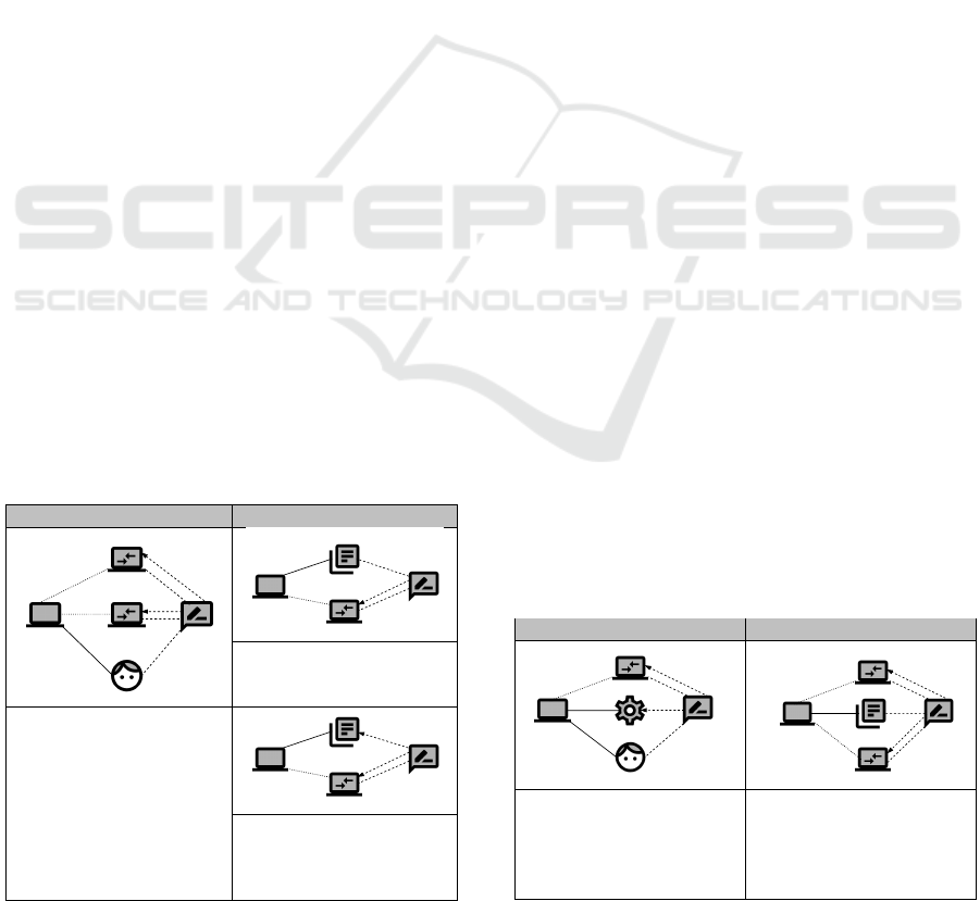
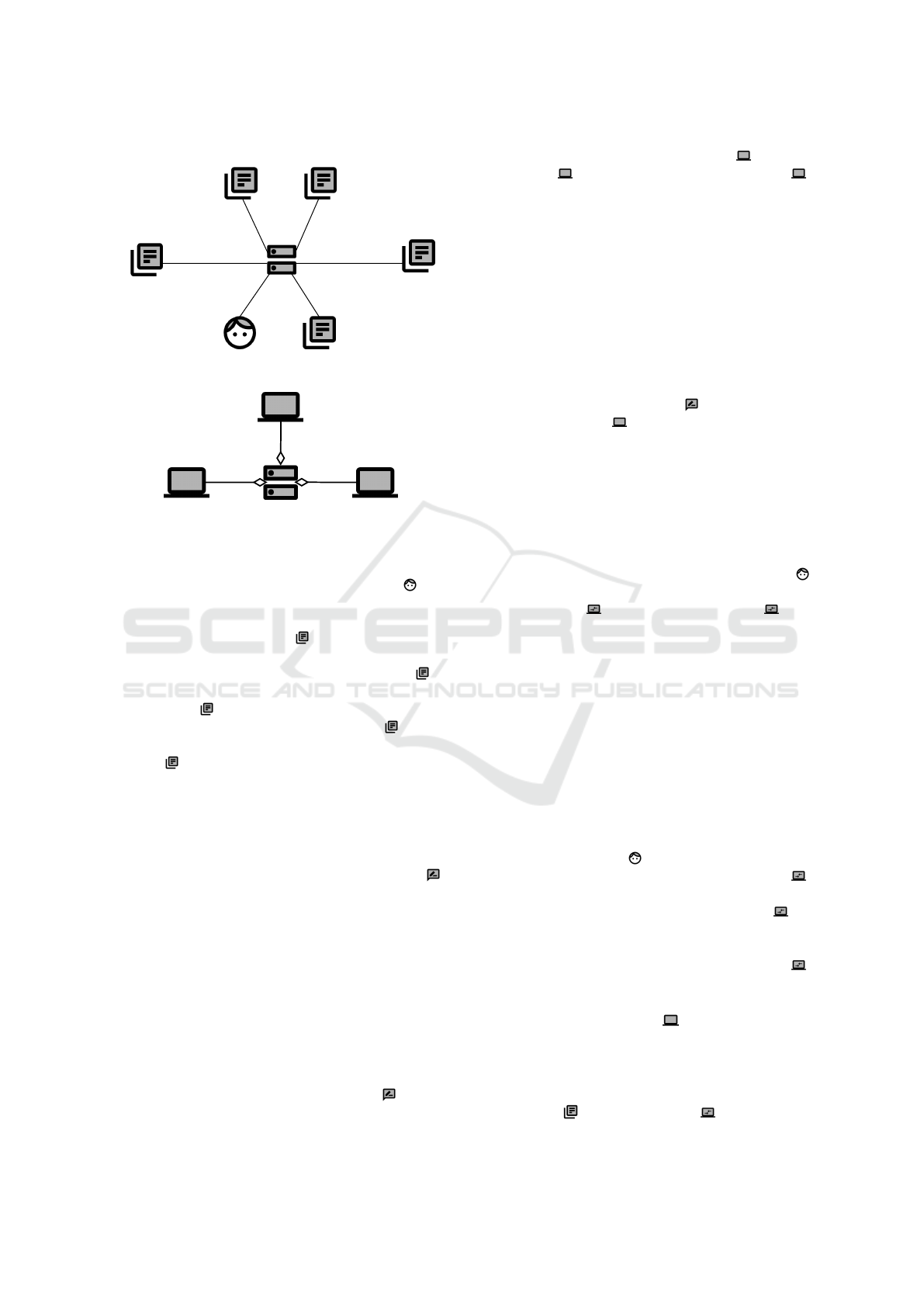
5.2 Context Diagram and Subsystems
In Figure 3, we present the context diagram and the
subsystems for our example.
The context diagram contains the File Sharing
Service , which we derived from the informal sce-
nario description. For the distributed system, we fur-
ther identified three subsystems. The User Peer is
employed by users of the P2P network for bootstrap-
ping and requesting files from other peers. The Over-
lay Service Provider is the mediator server that pro-
vides the peer descriptors for the bootstrapping pro-
cess. Finally, the File Holder Peer
represents a peer
from which a user can request files. Furthermore, this
peer can be used for bootstrapping since its IP address
is available at the overlay service provider.
ENASE 2021 - 16th International Conference on Evaluation of Novel Approaches to Software Engineering
246
File Sharing
Service
User
P2P
U!{joinOverlay, searchFile, requestFile}
FSS!{provideFileHolderIdentity}
FileHolder
Resources
FSS!{storeFile}
FHR!{requestedFile}
FSS!{getFile}
File Holder
Index
User
Resources
Repository of
Online Peers
FSS!{queryListOfPeers}
ROP!{availablePeers}
FileHolder
Cache
FSS!{updateCache}
FHC!{knownPeers}
FHI!{fileHolderIdentity}
FSS!{checkFileExists}
File Sharing
Service
User Peer
File Holder
Peer
Overlay Service
Provider
Figure 3: Example – Context diagram and subsystems.
In the context diagram, we document domains that
interact with the distributed system: A User can
initiate a command to join the overlay and can search
for and request files. The distributed system provides
a Repository of Online Peers that contains the peer
descriptors. When a new peer connects to an exist-
ing peer, this existing peer’s File Holder Cache is
updated with the new peer’s information. The File
Holder Index is the index of available files at a file
holder peer, and the File Holder Resources are the
files. A user’s files are represented by the User Re-
sources .
5.3 Select Frames
We use our frame library (see Section 4) to determine
a suitable frame for documenting the functional re-
quirement. For the requirement Join the network ,
we select the frame as follows. Since it is a distributed
requirement, we consider distributed frames as rele-
vant. Because the requirement is related to P2P sys-
tems, we further consider our P2P frames. The re-
quirement fits to the frame Bootstrapping Mediator-
based Approach (DF) (see Table 5).
In the next step, we create the problem diagrams
for each subsystem by instantiating the frame.
5.4 Create Problem Diagrams
Since the requirement Join the network is dis-
tributed, we create a problem diagram for each of
the involved subsystems: (i) User Peer , (ii) File
Holder Peer , and (iii) Overlay Service Provider .
The interface to problem domains in the environment
(e.g., lexical domains) can be taken from the context
diagram, whereas the interfaces between the different
subsystems (i.e., peers and overlay service provider)
are not yet contained in the context diagram. The
context diagram considers the distributed system as
a whole. Therefore, it is necessary to describe the
interaction between the subsystems in the problem
diagrams by defining appropriate interfaces and
phenomena.
User Peer. Figure 4 presents the problem diagram for
the requirement Join the network with regard to the
subsystem User Peer . Since the User Peer initiates
the connection with the other subsystems, we instanti-
ate the sender frame diagram for it. Using the textual
pattern, the corresponding functional requirement can
be formulated as follows:
A User can request a list of peers from the
Overlay Service Provider to connect to File
Holder Peer.
The diagram contains the machine itself, the User
who initiates the bootstrapping process, the Overlay
Service Provider , and the File Holder Peer . Be-
tween the user and the machine, there is a physical in-
terface containing the command joinOverlay, which
is initiated by the user. The interfaces between User
Peer, Overlay Service Provider, and File Holder Peer
are remote interfaces that describe the interaction be-
tween the different subsystems of the file sharing ser-
vice (see Figure 3). Since these interfaces are not yet
contained in the context diagram, they are defined in
the problem diagrams. The User Peer can request a
peer to connect from the Overlay Service Provider.
Afterwards, the User Peer joins the overlay using the
File Holder Peer, which grants access to the network.
The requirement refers to the phenomenon
joinOverlay of the User , the phenomenon grantRe-
questHP of the remote machine File Holder Peer ,
and the phenomenon returnPeerToConnectOSP of
the remote machine Overlay Service Provider . It
constrains the phenomenon queryListOfPeers, which
is the command to retrieve the online peers, and the
phenomenon updateCache of the File Holder Peer .
Overlay Service Provider. The problem diagram for
the Overlay Service Provider is included in Figure
5. The Overlay Service Provider is the mediator and
receives requests from the User Peer. We therefore in-
stantiate the first receiver frame diagram for this sub-
system. It consists of the machine, the Repository of
Online Peers , and the User Peer .
P2P Frames: Pattern-based Characterization of Functional Requirements for Peer-to-peer Systems
247
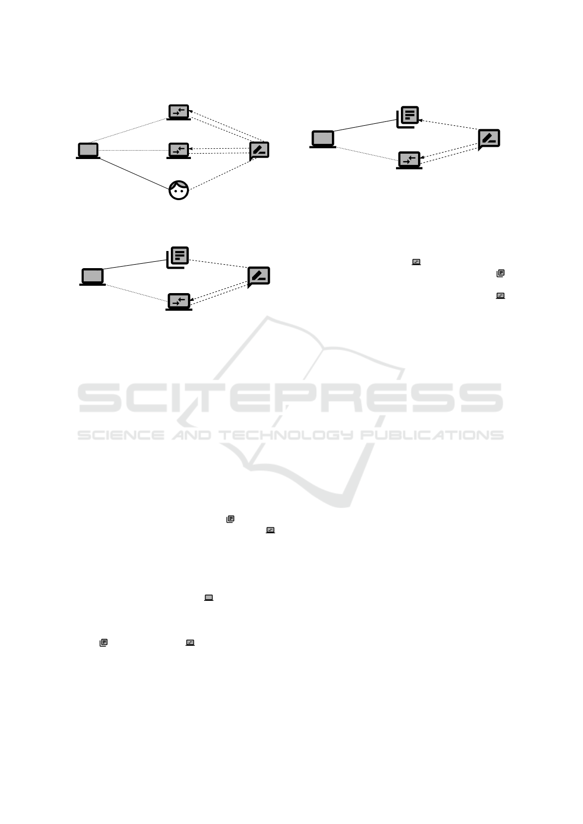
Join the
network
User Peer
File Holder
Peer
(N)
UP!{getPeerToConnectUP}
OSP!{returnPeerToConnectOSP}
(N)
UP!{joinOverlayUP}
FHP!{grantRequestFHP}
queryListOfPeers
grantRequestFHP
updateCache
Overlay Service
Provider
returnPeerToConnectOSP
User
joinOverlay
(P)
U!{joinOverlay}
Figure 4: Example – Problem diagram for User Peer.
Join the
network
Overlay Service
Provider
User Peer
JoinOverlayUP
getPeerToConnectUP
(N)
UP!{getPeerToConnectUP}
OSP!{returnPeerToConnectOSP}
(L)
OSP!{queryListOfPeers}
ROP!{availablePeers}
Repository of
Online Peers
availablePeers
Figure 5: Example – Problem diagram for Overlay Service
Provider.
With the textual pattern, the functional require-
ment for the subsystem can be formulated as follows:
User Peer can request a Repository of Online
Peers.
Since Peer User and Overlay Service Provider com-
municate via the Internet, the interface is a network
interface (N). There is a local interface (L) between
the Overlay Service Provider and the Repository of
Online Peers.
The Overlay Service Provider receives the request
for a peer to connect from the User Peer. The machine
queries the list of available peers from the repository
and returns a peer to connect to the User Peer.
The requirement refers to the phenomenon avail-
ablePeers (Repository of Online Peers ) and to the
phenomenon getPeerToConnectUP (User Peer ).
In addition, the requirement constrains the phe-
nomenon joinOverlayUP to trigger the establishment
of the connection to the returned peer.
File Holder Peer. Figure 6 presents the problem di-
agram for the File Holder Peer . We instantiate
the second receiver frame diagram for this subsys-
tem since it receives the request to connect from the
User Peer. It contains the machine, the File Holder
Cache , and the User Peer .
The functional requirement for the subsystem can
be formulated as follows using the textual pattern:
User Peer can establish a connection, and the
File Holder Cache can be updated with the
corresponding information.
Join the
network
File Holder
Peer
User Peer
connected
joinOverlayUP
(N)
UP!{joinOverlayUP}
FHP!{grantRequestFHP}
(L)
FHP!{updateCache}
FHC!{knownPeers}
File Holder
Cache
knownPeers
Figure 6: Example – Problem diagram for File Holder Peer.
The File Holder Peer receives the request from the
User Peer to join the overlay. Afterwards, it upgrades
the cache with information about the new peer and
grants access to the network.
The requirement refers to the phenomenon
joinOverlayUP (User Peer ), and it constrains the
phenomenon knownPeers (File Holder Cache ),
which represents the list of known peers in the cache,
as well as the phenomenon connected (User Peer ),
which represents the User Peer’s now connected state.
In this example, we have successfully divided our
described problem (connecting to an existing P2P sys-
tem) into smaller subproblems. The created require-
ments model now serves as a scaffold for the design
phase to derive an architecture for the system.
6 RELATED WORK
In the following section, we discuss related work that
follows a similar approach or that may complement
our work.
Our frames only address functional requirements.
For non-functional requirements such as security, spe-
cial P2P frames must be defined. There are problem
frames that constitute patterns for representing secu-
rity problems (Hatebur and Heisel, 2005). These are
specific types of problem frames defined to capture
known approaches to ensure security. It would be in-
teresting to extend our frames to the analysis of rel-
evant security requirements for P2P systems to con-
sider security concerns from the beginning of the de-
velopment process.
Beckers et al. have proposed context patterns that
enable a structured elicitation of domain knowledge
for specific technologies such as P2P systems (Beck-
ers et al., 2013). The instantiated context patterns can
be used as a basis for writing precise requirements.
These authors have also based their approach on Jack-
son’s work. Since we focus on functional require-
ments, these proposed context patterns and our frames
for distributed systems can complement each other in
a requirements engineering process.
There are several design and architecture pat-
ENASE 2021 - 16th International Conference on Evaluation of Novel Approaches to Software Engineering
248

terns in the context of P2P systems (Amoretti and
Zanichelli, 2018; Grolimund and M
¨
uller, 2006). The
resulting pattern catalogs support the design and im-
plementation phases of the software engineering pro-
cess, while our work focuses on the requirements en-
gineering phase. By mapping our frames to appro-
priate design and architectural patterns, we can also
assist the design phase during software development.
Haley suggests to use cardinalities to problem dia-
grams to specify interfaces between domains in a dis-
tributed system in more detail (Haley, 2003). Adding
cardinality notation to P2P frame diagrams would al-
low us to specify the communication between differ-
ent subsystems in more detail.
There are also improvements for P2P techniques
in general, such as combining peer caches with a me-
diator (Knoll et al., 2008). Such proposals attempt
to combine the advantages of both approaches. With
the help of our two bootstrapping frames, which now
serve as a basis for refinement in addition to the basic
frames for distributed systems, hybrid bootstrapping
variants that combine these approaches can be mod-
eled more easily.
Finally, a literature review discusses the current
status of requirements engineering for distributed
computing (Ramachandran and Mahmood, 2017).
The authors focus on cloud computing, which has be-
come increasingly popular in recent years. While we
have limited ourselves to P2P systems in this paper,
their work can serve as input for further analysis of
frames for distributed systems in the context of cloud
computing. Our frame library could be extended to
include special cloud frames.
7 CONCLUSION AND FUTURE
WORK
Summary. The main contribution of our paper are
P2P frames, which capture typical functional require-
ments in P2P systems. These patterns are an exten-
sion of Jackson’s problem frames and the frames for
distributed systems. We restricted ourselves to boot-
strapping, query routing in unstructured networks,
and direct data transfer between peers. Since we use
a consistent description format, the set of frames can
easily be extended. In addition, we proposed a frame
library system that supports the process of require-
ments engineering and that also incorporates our new
P2P frames. This library system helps software de-
velopers to systematically identify suitable frames for
their functional requirements. They can instantiate a
selected frame for their specific problems. Each frame
for distributed systems can be further refined to cap-
ture specific aspects of distributed systems, thereby
establishing new categories of frames (e.g., our P2P
frames). Our library can be integrated into require-
ments engineering processes and supports the selec-
tion of suitable frames to document functional re-
quirements.
Outlook. In future work, we plan to extend our frame
library system with new categories (e.g., frames for
cloud computing). Our created P2P frames currently
represent a basic set of typical requirements in P2P
systems. We will continue to extend our library to
incorporate a growing set of frames. To make our
system publicly available, we plan to implement it as
a web service. Requirements engineers can look up
suitable frames. Furthermore, they can contribute to
the library by adding their own identified frames. It
would also be interesting to extend the idea of P2P
frames to the analysis of security-relevant require-
ments for P2P systems to address security concerns
from the beginning of the development process.
In summary, we believe that patterns should be
part of a software analyst’s standard toolkit and that a
comprehensive and extensible catalog helps both ex-
perienced developers as well as those with no P2P
systems experience.
REFERENCES
Amoretti, M. and Zanichelli, F. (2018). P2P-PL: A pat-
tern language to design efficient and robust peer-to-
peer systems. Peer Peer Netw. Appl., 11(3):518–547.
Beckers, K., Faßbender, S., and Heisel, M. (2013). A meta-
model approach to the fundamentals for a pattern lan-
guage for context elicitation. In Proceedings of the
18th European Conference on Pattern Languages of
Programs (Europlop).
Boldt, D., Felix, K., and Fischer, S. (2017). Decentralized
Bootstrapping for WebRTC-based P2P Networks. The
Fifth International Conference on Building and Ex-
ploring Web Based Environments (WEB2017), pages
17–23.
Buford, J., Yu, H., and Lua, E. K. (2008). P2P Networking
and Applications. Morgan Kaufmann Publishers Inc.,
San Francisco, CA, USA.
Choppy, C. and Heisel, M. (2004). Une approache
`
a base
de patrons pour la sp
´
ecification et le d
´
eveloppement
de syst
`
emes d’information. Approches Formelles dans
l’Assistance au D
´
eveloppement de Logiciels - AFADL.
Dinger, J. (2009). Das Potential von Peer-to-Peer-
Netzen und -Systemen : Architekturen, Robustheit und
rechtliche Verortung. Universit
¨
atsverlag Karlsruhe,
Karlsruhe.
FIRST.org (2019). Common vulnerability scoring system
v3.1: Specification document.
Grolimund, D. and M
¨
uller, P. (2006). A pattern language for
overlay networks in peer-to-peer systems. In Zdun,
P2P Frames: Pattern-based Characterization of Functional Requirements for Peer-to-peer Systems
249
U. and Hvatum, L. B., editors, EuroPLoP’ 2006,
Eleventh European Conference on Pattern Languages
of Programs, Irsee, Germany, July 5-9, 2006, pages
95–140. UVK - Universitaetsverlag Konstanz.
Haley, C. B. (2003). Using problem frames with dis-
tributed architectures: A case for cardinality on inter-
faces. In ICSE 2003 - Proceedings of 2nd Interna-
tional Software Requirements to Architectures Work-
shop, STRAW 2003, May 9, 2003, Portland, Oregon,
USA, pages 130–133.
Hatebur, D. and Heisel, M. (2005). Problem frames
and architectures for security problems. In Winther,
R., Gran, B. A., and Dahll, G., editors, Computer
Safety, Reliability, and Security, 24th International
Conference, SAFECOMP 2005, Fredrikstad, Norway,
September 28-30, 2005, Proceedings, volume 3688 of
Lecture Notes in Computer Science, pages 390–404.
Springer.
Hauswirth, M. and Dustdar, S. (2005). Peer-to-peer: Grund-
lagen und architektur. Datenbank-Spektrum, pages 5–
13.
Jackson, M. A. (2000). Problem Frames - Analysing and
Structuring Software Development Problems. Pearson
Education.
Knoll, M., Wacker, A., Schiele, G., and Weis, T. (2008).
Bootstrapping in peer-to-peer systems. In 14th Inter-
national Conference on Parallel and Distributed Sys-
tems, ICPADS 2008, Melbourne, Victoria, Australia,
December 8-10, 2008, pages 271–278. IEEE Com-
puter Society.
Ramachandran, M. and Mahmood, Z. (2017). Require-
ments Engineering for Service and Cloud Computing.
Springer, 1st edition.
Wirtz, R., Heisel, M., and Wagner, M. (2020). Distributed
frames: Pattern-based characterization of functional
requirements for distributed systems. In Software
Technologies - 14th International Conference, IC-
SOFT 2019, Prague, Czech Republic, July 26–28,
2019, Revised Selected Papers, volume 1. Springer In-
ternational Publishing.
APPENDIX
Search File.
In Figures 7 and 8, we present the problem diagrams
for the requirement that users can search for files in
the network.
Search File
User Peer
File Holder
Peer
(N)
UP!{searchFileUP}
FHP!{provideFileHolderIdentityFHP}
provideFileHolderIdentityFHP
checkFileExists
User
searchFile
(P)
U!{searchFile}
(L)
UP!{provideFileHolderIdentityD}
content
User Display
Figure 7: Example – Search file for User Peer.
Search File
File Holder
Peer
File Holder
Peer
searchFileUP
(L)
FHP!{checkFileExists}
FHI!{fileHolderIdentity}
fileHolderIdentity
File Holder
Index
User Peer
(N)
UP!{searchFileUP}
FHP!{provideFileHolderIdentityFHP}
(N)
FHP!{searchFileFHP}
FHP!{provideFileHolderIdentityFHP}
provideFileHolderIdentityUP
checkFileExistsFHP
provideFileHolderIdentityFHP
Figure 8: Example – Search file for File Holder Peer.
Transfer File.
In Figures 9 and 10, we present the problem diagrams
for the requirement that users can transfer files from
another peer to their own one.
Transfer File
User Peer
File Holder
Peer
(N)
UP!{requestFileUP}
FHP!{fileTransferFHP}
fileTransferFHP
getFile
User
requestFile
(P)
U!{requestFile}
(L)
UP!{storeFile}
file
User
Resources
Figure 9: Example – Transfer file for User Peer.
Transfer File
File Holder
Peer
User Peer
storeFileUP
requestFileUP
(N)
UP!{requestFileUP}
FHP!{fileTransferFHP}
(L)
FHR!{requestedFile}
FHP!{getFileFHP}
FileHolder
Resources
files
Figure 10: Example – Transfer file for File Holder Peer.
ENASE 2021 - 16th International Conference on Evaluation of Novel Approaches to Software Engineering
250
