
Modeling Methodology for Reconfigurable Distributed Systems using
Transformations from GR-UML to GR-TNCES and IEC 61499
Soumoud Fkaier
1,2,3
, Mohamed Khalgui
2,3
and Georg Frey
1
1
Chair of Automation and Energy Systems, Saarland University, Saarbruecken, Germany
2
Tunisia Polytechnic School, Carthage University, Tunis, Tunisia
3
INSAT LISI Lab, Carthage University, Tunis, Tunisia
Keywords:
Methodology, Modeling, Model Transformation, Microgrid, UML, GR-TNCES, IEC 61499.
Abstract:
As today’s reconfigurable distributed control systems become more and more complex, the modelling of its
controlling applications becomes more difficult. The Unified Modelling Language (UML) is considered as a
standard language for modelling software and systems. However, UML does not provide formal semantics
that allow correctness verification. It also has no semantics to design probabilistic scenarios running un-
der energy and memory constraints. Moreover, despite its numerous assets when used to model Distributed
Control Systems (DCS), UML still do not allow the simulation of models in some DCS hardware platforms.
To overcome these limitations, we propose in this paper a new UML profile called GR-UML (Generalized
Reconfigurable-UML) to model the mentioned features. Then, we introduce a modeling methodology that
allows to use GR-UML, formal verification, and models deployment according to the IEC 61499 DCS stan-
dard. The paper presents also the rules responsible for automatic transformation of GR-UML to GR-TNCES
(a Petri net formalism used for formal verification) and to function blocks (the elementary unit of the IEC
61499 standard). These transformations are implemented in a software tool. The contributions of the paper
are proved using an example of microgrid control application example.
1 INTRODUCTION
UML is a semi-formal modelling language used for
the specification and modelling of software systems.
It provides graphical representations using different
diagrams that allow to illustrate standardized view to
a particular scope of a system. Thanks to its vari-
ous advantages, UML is adopted to design many sys-
tems including the industrial DCS (Castellanos et al.,
2017), (Oueslati et al., 2018). Despite its undeniable
assets, UML still has some limitations, among them
we focus on two main ones: UML does not guaran-
tee the models correctness, and it does not provide
the ability to execute models in some target hardware
platform of DCSs. UML has also some hurdles to de-
fine the event flow concept which is very important
for distributed systems. It also does not define se-
mantics to model probabilistic scenarios running un-
der memory and energy constraints.
Concerning the models correctness, the litera-
ture is rich with transformations between UML and
formal verification techniques. For example, in early
2002, the authors of (Jansen et al., 2002) have pro-
posed a solution to add probability to statecharts then
to use model checking on the generated models. De-
spite its importance, this solution does not consider
the reconfiguration, timing, and the resources us-
ages constraints (Fkaier et al., 2016b), (Fkaier et al.,
2016a), (Fkaier. et al., 2017). Later, the authors of
(Addouche et al., 2006) have extended the class and
statechart diagrams with real-time requirements and
have introduced a methodology to verify probabilistic
properties. In (Nokovic and Sekerinski, 2013), the au-
thors have also extended the statechart diagram with
probabilities and based on it they have created a soft-
ware toolkit to design probabilistic properties of com-
plex systems. But there is no consideration to timing,
reconfiguration, and resources usage. The authors of
(Salem et al., 2015a) have proposed a UML profile
to extend its existing semantics with reconfiguration
and shared resources control. They have also intro-
duced a transformation to the formalism R-TNCES (a
Petri nets extension allowing the verification of recon-
figuration functions) in order to verify timed proper-
ties. Although the latter represents an important con-
tribution, it does not allow the possibility to model
Fkaier, S., Khalgui, M. and Frey, G.
Modeling Methodology for Reconfigurable Distributed Systems using Transformations from GR-UML to GR-TNCES and IEC 61499.
DOI: 10.5220/0010422102210230
In Proceedings of the 16th International Conference on Evaluation of Novel Approaches to Software Engineering (ENASE 2021), pages 221-230
ISBN: 978-989-758-508-1
Copyright
c
2021 by SCITEPRESS – Science and Technology Publications, Lda. All rights reserved
221

and verify probabilistic requirements and applications
running under memory and energy constraints.
Concerning the possibility to run models in
specific hardware platform, since its appearance
IEC 61499 have been a subject of transformations
to other modelling languages, formal and non-formal
ones, as it tackles deeply the technical side of appli-
cations models while other scopes are omitted. The
function block concept does not use many of the
component-based and object-oriented software engi-
neering. In (Tranoris and Thramboulidis, 2002) and
(Thramboulidis, 2004), UML concepts have been in-
cluded in the specification and modelling using dif-
ferent diagrams for determining the subsequent func-
tion block diagrams. The authors of (Dubinin et al.,
2005) have proposed a framework for the design of
distributed control using a combination of function
blocks with UML. Statechart, cooperation, class, and
sequence diagrams are transformed to the executable
function blocks. In (Panjaitan and Frey, 2006b), (Pan-
jaitan and Frey, 2006a), and (Hussain and Frey, 2007)
authors have proposed transformation concepts from
class, packages, and statechart diagrams to models in
terms of IEC 61499. Despite the importance of these
works, more detailed transformations may ensure bet-
ter quality, especially for the mapping of combined
structural and behavioral aspects of an application.
As it can be seen from the study of the exist-
ing works, there is still a need for techniques en-
abling better features coverage and better modeling
efficiency. First, currently there is no UML semantics
defining the probability and resources constraints to-
gether in one approach. Second, existing attempts to
bring together UML and function blocks are still sim-
ple and more details are required. More importantly,
there is a crucial need to a systematic methodology
defining the modeling process of correct and consis-
tent models. It is especially significant to provide a
software tool guaranteeing the mapping of models.
In this paper, we propose first a new UML profile
called GR-UML enriched with semantics enabling
the modeling of probabilities and limited resources
(mainly memory and energy). Thanks to the exten-
sibility mechanisms of UML, we define new stereo-
types and improve the class and statechart diagrams.
Afterwards, we define transformation rules from GR-
UML to the Petri nets formalism GR-TNCES as well
as to the IEC 61499 function blocks. Then, we define
a modeling methodology that consists of three phases:
(1) modeling applications using GR-UML, (2) per-
forming formal verification of the created models, and
(3) performing analysis of the function block models.
In order to facilitate the use of the proposed concepts
(i.e., UML profile, methodology and transformations)
a software tool is introduced. To show the suitability
of the proposed concepts an example of microgrids
software is considered.
The layout of the paper is organized as follows.
Section 2 presents the background. Section 3 intro-
duces the new UML profile and the corresponding
transformations. Section 4 presents the methodology
and the software tool. Section 5 shows the suitability
through the case study. Finally, Section 6 concludes
the paper and presents future perspectives.
2 BACKGROUND
This section provides an overview of the used con-
cepts. First we present the GR-TNCES formalism.
Then, we present the IEC 61499 standard through a
formal definition of its concepts.
2.1 GR-TNCES
GR-TNCES is an extension of the formalism R-
TNCES which in addition to the reconfiguration and
timed features of the Net Condition/Event systems, it
includes the ability to capture probability and mem-
ory and energy resources control. As presented in
(Khlifi et al., 2015), the GR-TNCES formalism is
defined as a network of R-TNCES as follows: G=
{
∑
R-TNCES}, where R-TNCES=(B,R) with B be-
ing the behavior module and R being the control
module. The behavioral module B is defined as
a union of multiple TNCES and defined as B =
(P,T, F,QW,CN,EN,DC,V,Z
0
), with (i) P is a fi-
nite non-empty set of places. (ii) T is a finite non-
empty set of transitions. (iii) F is a set of flow arcs
such that F ⊆ (P × T ) ∪ (T × P) QW = (Q,W) with
Q : F → [0, 1] is the probability of the arc and W is
a mapper that maps a weight to a flow arc such that
(P × T ) ∪ (T × P) → {0,1}, W(x,y) > 0 if (x,y) ∈ F
and W (x,y) = 0 otherwise, with x and y ∈ P ∪ T . (iv)
CN is a set of condition signals with CN ⊆ (P × T ).
(v) EN is a set of event signals with EN ⊆ (T × T ).
(vi) DC is a superset of time constraints on output arcs
such that F ⊆ (P × T ) → [l, h]. (vii) V : T → {∨,∧}
indicates an event processing mode to each transition
(AND or OR). (viii) Z
0
= (T
0
,D
0
) where T
0
: P →
{0,1} is the initial marking position and D
0
: P → {0}
is the initial clock position.
2.2 IEC 61499
IEC 61499 is the standard of the distributed control
systems (Miguel-Escrig et al., 2020). IEC 61499 of-
fers a function block concept which has three main
ENASE 2021 - 16th International Conference on Evaluation of Novel Approaches to Software Engineering
222

function block types: basic (BFB), composite (CFB),
and service interface (SIFB) function blocks. In the
following our formal definition of the IEC 61499 con-
cepts are presented. No matter its type, a function
block is defined by an interface, noted I, and an inter-
nal structure. The interface I of all types of function
blocks is defined as I = (IE,OE,ID, OD, IW, OW ),
where (i) IE (resp. OE) is a set of input (resp. out-
put) events. (ii) ID (resp. OD) is a set of input (resp.
output) data. (iii) IW (resp. OW ) is a set of With-
associations for inputs (resp. for outputs).
A basic function block is given by BFB =
(I,ECC,A)., where I is its interface, ECC is the Ex-
ecution Control Chart, and A is the encapsulated al-
gorithms defining the functionalities of a BFB and it
is given by A = {alg
i
|i ∈ {1, ...,|A|}}., where alg
i
is
an algorithm. ECC is the chart supervising the op-
eration of a function block. It is defined by ECC =
(ES,EA,ET, EF), where (i) ES is a set of states of
ECC. (ii) EA is a set of actions. An action is asso-
ciated to an algorithm alg
i
and a subset of the output
events of I. (iii) ET is a set of transitions between
ECC states. Each transition has a guard condition
which is the coming of an input event of I. (iv) EF is
a set of arc flows that indicates the flow between the
different ECC states.
A composite function block is given by CFB =
(I,N), where N is a network of BFB and/or CFB. A
SIFB type represents an interface to some services of-
fered by the operating system and/or the device. For
instance, interface to hardware (e.g., sensors) or com-
munication services (client/server communication).
3 NEW UML PROFILE: GR-UML
This section introduces the new UML profile called
GR-UML and its transformations to GR-TNCES and
to IEC 61499 function blocks.
3.1 GR-UML
The new profile defines formal semantics to define
probabilities and memory & energy resources con-
straints in one model. To this end, we enhance both
structural and behavioural views through the class and
state diagrams defined in (Salem et al., 2015a). We in-
troduce a formal definition of the component diagram
since we need it later for transformations.
3.1.1 Structural View
This section defines the enhanced class diagram and
the component diagram.
Definition of UML Class Diagram. UML class di-
agram is offered as one of the structural view en-
ablers of systems and applications. It expresses the
system structure by showing a set of classes, their at-
tributes, their methods, and the relations among ob-
jects. To make the semantics of this diagram more
suitable to the probabilistic reconfigurable systems
that operate under resources constraints (i.e., mem-
ory and energy), we extend its vocabulary by defin-
ing new stereotypes to express the probabilistic prop-
erty. Thus, we extend the solution proposed in (Salem
et al., 2015a) by defining new stereotypes of the class
attributes as follow:
• probability : depicts that the said attribute is
a probabilistic functionality/operation.
• energy : depicts that the said attribute repre-
sents energy resources of an operation.
• memory : depicts that the said attribute rep-
resents memory resources of an operation.
For DCSs, it is often required to model equipment re-
sources consumption especially memory and energy
ones. Hence, it is required to have relevant methods
for it. Thus, we define these methods:
• checkEnergy(name : string) : bool - controls the
energy resources defined by name.
• checkMemory(name : string) : bool - controls the
memory resources defined by name.
Based on these semantic extensions, a class di-
agram is now defined as follows: ClDiag =
{Cl, At,Me,S,ψ, ω}, where (i) Cl = {cl
1
,cl
2
,...,cl
m
}
is a finite set of classes. (ii) At = {at
1
,at
2
,...,at
n
}
is a finite set of attributes of classes. (iii)
Me = {setInput,resetInput, setOut put,resetOut put,
checkEnergy, checkMemory; setCeiling} is a set of
methods of the classes. (iv) S = { probability
, memory , energy , in , out
, input , out put , eventInput ,
eventOut put , boolean , integer } is
a finite set of stereotypes. (v) ψ : at
i
→ cl
j
is a
function mapping the attribute at
i
to the class cl
j
. (vi)
ω : s
i
→ at
j
is a function mapping the stereotype s
i
to
the attribute at
j
.
Definition of UML Component Diagram. In this
paper, only simple components of the UML compo-
nent diagram are used. Hence, we define a compo-
nent diagram, denoted by ComDiag, as ComDiag =
{Co,In, α
dep
,α
rea
}, where, (i) Co is a finite set of
components of ComDiag. (ii) In is a finite set of in-
terfaces of ComDiag. (iii) α
dep
is a finite set of de-
pendency relationships of components to interfaces
such that α
dep
⊆ (In ×Co). (iv) α
rea
is a finite set of
Modeling Methodology for Reconfigurable Distributed Systems using Transformations from GR-UML to GR-TNCES and IEC 61499
223

realization relationships of interfaces by components
such that α
rea
⊆ (Co × In).
3.1.2 Behavioral View
State diagram is used to characterize the behav-
ior of objects. Guard conditions can now include
the probabilty stereotype that enables to ex-
press probabilistic transition between states. A
UML state diagram is then defined as, StDiag =
{St,Tr,Ev,G,Ac,Fr,Jn,Fl,Ch,ρ,γ,δ, ε}, where (i)
St = {st
1
,st
2
,...,st
n
} is a finite set of states in StDiag.
(ii) Tr = {tr
1
,tr
2
,...,tr
m
} is a finite set of transitions
in StDiag. (iii) Ev is a finite set of events in transitions
of StDiag. (iv) G is a finite set of guards in StDiag.
(v) Ac is a finite set of actions in StDiag. (vi) Fr is
a finite set of fork pseudostates in StDiag. (vii) Jn is
a finite set of join pseudostates in StDiag. (viii) Fl
is a finite set of the transitions flow, such that Fl ⊆
(St × Tr) ∪ (Tr × St). (ix) Ch is a finite set of choice
pseudostates. (x) ρ: Gr
i
probability
⊂ Gr → Tr
i
⊂ Tr
is a condition ensuring that the subset of guard con-
ditions Gr
i
probability
assigned to a subset of transitions
Tr
i
leaving a state st
i
sum to one. (xi) γ: ev
i
→ tr
j
is a
function mapping an event ev
i
of Ev to a transition tr
j
of Tr. (xii) δ: gr
k
→ tr
j
is a function mapping a guard
gr
k
of Gr to a transition tr
j
of Tr. (xiii) ε: act
l
→ tr
j
is a function mapping an action act
l
to a transition tr
j
.
3.2 Transformation to GR-TNCES
For better modeling flexibility and easiness, we pro-
pose the following list of transformation rules that
map GR-UML models to GR-TNCES:
Rule 1: In an StDiag, guards stereotyped with
probability are transformed to the set QW of the
behavioral module B of GR-TNCES. A probabilistic
guard gr has the form of [Proba
i
== x] where Proba
i
stands for the probability on the transition and x ∈
[0..1] is the value of the probability.
Rule 2: In an StDiag, some actions can be trans-
formed to some transitions. An action ac corresponds
to four event arcs, ea, in an GR-TNCES. An event
output signal, eo, is added to the transition from
which the event is triggered and an event input sig-
nal, ei, as well as an transition t
ac
are added to the
related transition t.
Rule 3: A fork pseudostate f r that splits an StDiag
transition tr into several orthogonal regions of a com-
posite state cst, is mapped to a transition t
f r
a
linked to
a place p
cst
presenting the composite state cst, and
p
cst
is linked to a transition t
f r
b
that is linked to n
places presenting the internal simple states of a cst.
Rule 4: A join pseudostate jn that merges StDiag
transitions from several orthogonal regions of a com-
posite state cst, is mapped to a transition t
jn
a
that is
linked to n places of the internal simple states of a cst,
t
jn
a
is linked to a place p
cst
presenting the composite
state cst, and p
cst
is linked to a transition t
jn
b
.
Rule 5: A choice pseudostate ch that splits an
StDiag transition to multiple conditional outgoings is
transformed to a decision state along with transition
t
ch
that is linked to n places representing the target
states, also n input/output condition signals are added
as follows: a condition output signal, co, is added to
the place guaranteeing the condition and a condition
input signal, ci, to the related transition. .
3.3 Transformation to IEC 61499
In order to allow a smooth transformation of the cre-
ated GR-UML model into function blocks model, we
introduce the hereafter transformation rules.
Rule 6: A component co ∈ Co of the compo-
nent diagram ComDiag is transformed to a composite
function block CFB.
Rule 7: In UML component diagram, as it is the
case for class diagram, interfaces contain methods,
where each method has a name, a set of input argu-
ments defined by their name and type, and a return
value defined by its type. An interface in ∈ In realized
by a component co
a
and used by a component co
b
is
transformed to inputs of the interface I
b
(i.e., subsets
of IE,ID,IW ) of function block f b
b
and a part of the
interface I
a
(i.e., subsets of IE, ID,IW,OE, OD,OW )
of function block f b
a
.
Rule 8: Based on Rule 7, methods defined an in-
terface in are transformed to I
p
as follows:
1. A provided method defined in in is transformed
to an input event ie
i
∈ IE with the related associ-
ation iw
i
∈ IW as well as the relevant input data
id
i
⊂ ID, such that the name of the method is
transformed to the name of event, the arguments
of the method are transformed to the associated
data, and the types of method arguments are the
transformed to the type of input data.
2. The output of the provided method is transformed
to an output event oe
i
∈ OE with the related as-
sociation ow
i
∈ OW as well as the relevant output
data od
i
⊂ OD, such that the return type is the out-
put data type.
Rule 9: Based on Rule 7, required methods de-
fined an interface in are transformed to I
b
as follows:
Each method defined in in is transformed to an input
event ie
i
∈ IE with the relevant association iw
i
as well
as the relevant input data id
i
⊂ ID, such that the name
of the method is transformed to the name of event and
ENASE 2021 - 16th International Conference on Evaluation of Novel Approaches to Software Engineering
224

the arguments of the method are transformed to the
associated data. The types of arguments are trans-
formed to the type of data.
Rule 10: The internal activity of each module is
transformed according to its state diagram as follows:
every simple state is transformed to a BFB while ev-
ery composite state is transformed to a CFB.
Rule 11: A state requiring the use of a resource
access is transformed to SIFB.
Rule 12: States of a state diagram do generally
hold a set of internal activities (entry action, do activ-
ity action, exit action). These actions are transformed
to the algorithms of a BFB. The evolution of state
activities are transformed to the ECC.
Rule 13: A transition tr
i
∈ Tr that is leaving a state
st
p
and entering a state st
q
is mapped to transitions
linking an output event oe
i
∈ OE
p
and the related out-
put data od
i
⊆ OD
p
to the input event ie
i
∈ IE
q
and
the related input data id
i
⊆ ID
q
.
Rule 14: A guard gr
p
associated to a transition
tr
p
linking a state st
p
to a state st
q
is transformed to
output data od
i
along with a with-association ow
i
of
the interface of the source function block f b
p
and to
input data id
i
along with a with-association iw
i
of the
interface of the destination function block f b
q
.
4 MODELING METHODOLOGY
In order to generate more powerful, consistent, and
efficient applications models, we propose to verify
the created GR-UML models using formal verifica-
tion and to analyze models in accordance with IEC
61499. From the one side, formal verification allows
to get sureness about the behavior since mathemati-
cal extensive model testing is used. It helps also to
catch errors and ambiguities in early stages and con-
sequently offer the opportunity to fix them in low cost
manner (time and effort). From the other side, an-
alyzing the function block models allows to execute
applications in target hardware environments. There-
fore to get a fine-grained executable model.
To make the move from GR-UML to GR-TNCES
and to IEC 61499 function blocks easy, the transfor-
mation rules introduced in the previous section are
implemented in a software tool.
4.1 Methodology Flow
The proposed modeling methodology is composed of
the following three phases. An overview of the pro-
posed methodology is depicted in Figure 1.
Phase 1: Modelling Applications using GR-UML.
In this phase applications models are elaborated us-
ing the new semantics of GR-UML. Structural and
behavioral views can now cover the probabilistic as
well as the memory and energy control. Creating ab-
stract models of any application before implementa-
tion helps to reach clear unified view.
Phase 2: Formal Verification. After creating the
GR-UML models of a certain application, proving
and/or disproving some properties can be conducted
in this phase. Formal verification and validation can
be conducted using mathematical basis. The GR-
UML models are edited, visualized, simulated using
the new software extension to ZIZO tool (Salem et al.,
2015b) -which we will present in the next section-. At
the end of a simulation with ZIZO, a report is gen-
erated that contains the number of explored places,
the elapsed time, and whether deadlocks exist. The
new software tool allows also to export the created
GR-UML models to GR-TNCES editor in the form
of ”.zz” files. ZIZO offers the possibility to transform
GR-TNCES to PRISM model checker, so that model
checking using CTL and PCTL formulas can be con-
ducted. In this phase, the model is examined, verified,
and analyzed, and whenever some non desirable be-
haviors are catched, the GR-UML can be refined until
the target result is obtained.
Phase 3: Model Analysis According to IEC 61499.
After having verified the correctness of the created
models using formal verification, it becomes pos-
sible now to generate function blocks models in
compliance with IEC 61499 and test its suitabil-
ity/performance. The new software tool allows to
export the GR-UML models in the form of ”.fbt”
files readable by some function blocks tools such as
FBDK
1
and 4DIAC
2
. In this phase, the function block
model can be deployed in a specific hardware plat-
form for example simulating RaspberryPies, Ethernet
communication, etc. Analysis can be conducted espe-
cially the modular distributed behavior and the event-
driven aspects of a DCS.
4.2 Software Tool: ZiZo
ZiZo tool, as presented in (Salem et al., 2015b), is
initially created to be a visual software environment
for the modeling and verification of R-TNCES and
GR-TNCES systems. Since we are using GR-TNCES
for formal verification, we add new components, fea-
tures and views to ZiZo in order to get a complete en-
vironment implementing the proposed methodology
(the process flow depicted in Figure 1).
We have added the ability to model software ac-
cording to the formal definition of GR-UML. The tool
1
http://ftp.holobloc.com/fbdk2/index.htm
2
https://www.eclipse.org/4diac/
Modeling Methodology for Reconfigurable Distributed Systems using Transformations from GR-UML to GR-TNCES and IEC 61499
225
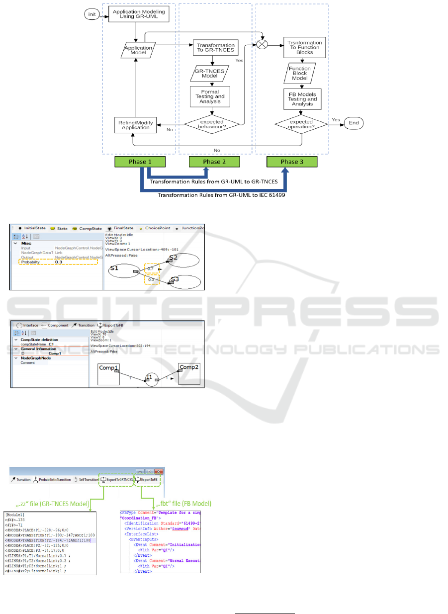
Figure 1: Proposed Methodology Flow.
Figure 2: ZIZO probabilistic state diagram editor.
Figure 3: ZIZO component diagram editor.
supports the modeling of probabilistic guards through
adding probabilities on transitions as depicted in Fig-
ure 2. It also provide the ability to model component
diagrams as depicted in Figure 3.
Figure 4: ZiZo Transformations: export to GR-TNCES and
export to function blocks.
More importantly, the new ZiZo facilitates the
task of designers through offering the ability to auto-
matically transform created GR-UML models to GR-
TNCES by a simple click on ”ExportToGRTNCES”
button which hides behind it the implementation of
the transformation rules defined in the previous sec-
tion. A ”.zz” file is created and can be loaded in the
ZiZo GR-TNCES viewer. Then simulation, reacha-
bility, time constrainted scenarios can be analyzed.
The GR-TNCES viewer offers also the possibility to
export models to PRISM
3
model checker in the form
of ”.pm” files. Hence, CSL, CTL, and PCTL formulas
can be used. Likewise, a click on the button ”Export-
ToFB” allows to generate ”.fbt” file readable by some
of the function block tools as depicted in Figure 4.
5 CASE STUDY
In order to show the efficiency of the proposed
methodology and tool, we model the control applica-
tion of a reconfiguration agent of a microgrid-based
electricity grid as an example.
5.1 Case Presentation
A microgrid is a small-scale electricity grid composed
of four main subsystems, as reported in (Fkaier. et al.,
2020a), electricity generation subsystem (traditional
and/or renewable sources), consumption subsystem,
energy storage subsystem, and prosumers subsystem.
Microgrids can operate in islanded mode or also in
connection to the utility grid. The operation of mi-
crogrids is generally performed using a set of re-
3
http://prismmodelchecker.org/
ENASE 2021 - 16th International Conference on Evaluation of Novel Approaches to Software Engineering
226
motely controlled/operated switches that help greatly
to reroute power which is substantial for reconfigura-
tion functionalities (Fkaier. et al., 2020b).
One of the important contributions of microgrids
lies in the integration of renewable energy sources
(RES) such as the wind, sun, and water (see Figure 5).
However, these sources are of uncertain behavior and
despite the enhanced forecasting methods, generation
fluctuations are still occurring. This topic is a major
concern in the last years and many researchers try to
find solutions to the intermittent supply. Probability
theory is used by most of the existing works such as
the one reported in (Hemmati et al., 2020).
In this paper, we study the case of neighbor micro-
grids that can supply each other in order to overcome
shortages that may happen to one them. Reconfigura-
tions must take place in order to minimize the down-
time and consequently to save the system reliability.
We aim to model and analyze the capability of mi-
crogrids to operate in islanded mode, especially the
successful reconfigurations in cases of RES shortage.
In the considered example, we assume that a Recon-
figuration Agent (RA) is responsible for the reconfig-
urations and power rerouting among of microgrids.
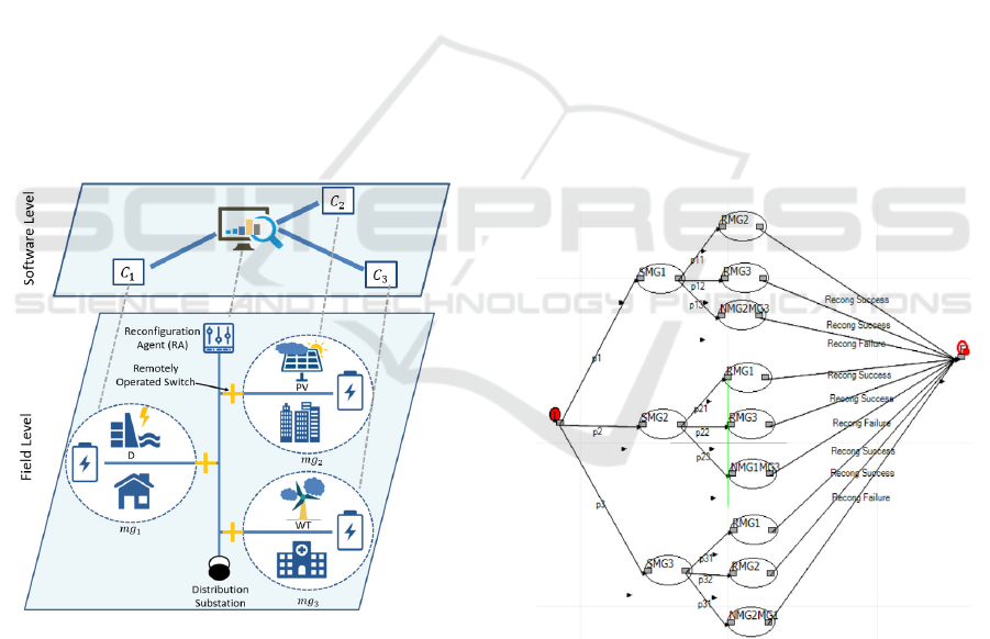
Figure 5: Microgrid-based system.
Figure 5 depicts the considered system with three
microgrids mg
1
, mg
2
, and mg
3
, as well as the RA.
Through the chosen scenario, we demonstrate how
the GR-UML as well as the proposed methodology
help to achieve reliable models. Due to space limi-
tations, we content with showing the probabilistic se-
mantics of GR-UML and we omit the resources con-
trol of applications (memory and energy usage of the
used hardware). We start with modeling the recon-
figuration scenarios of RA using the state diagram of
GR-UML, then we verify the models correctness by
estimating the probabilities of successful reconfigura-
tions, finally we test the deployment of the models in
a function blocks hardware platform.
5.2 Modeling with GR-UML
As shown in Figure 5, the microgrid mg
1
(resp. mg
2
,
mg
3
) relies on water dams (D) (resp. photo-voltaic
panels (PV), wind turbines(WT)) as RES. Let us sup-
pose that the period of analysis is the three months of
the summer season, given by d = 3 × 30 × 24 × 3600,
where 3 is the number of months, 30 is the number
of days per month, 24 is the number of hours per day,
3600 is the number of seconds per hour. Let e
n
be
the amount of the needed energy by a microgrid, and
e
r
is the amount of the reserve energy saved by a mi-
crogrid (i.e., surplus). When an electricity shortage is
occurring in one microgrid, the reconfiguration agent
(RA) tries first to find the needed amount in the other
two microgrids. If the amount is affordable, then a re-
configuration is applied through opening/closing the
remotely operated switches SW
1
(resp. SW
2
, SW
3
) cor-
responding to mg
1
(resp. mg
2
, mg
3
). If the amount is
not affordable, then a switch to the utility connected
mode is applied.
Figure 6: GR-UML: state diagram of the logic of RA.
Let us assume that the probability of electricity
shortage of mg
1
(resp. mg
2
, mg
3
) that relies on D
(resp. PV, WT) during the summer is ten times,
p
1
= 10/d = 1.28E-06, (resp. three times p
2
= 3/d =
3.85E-07, six times p
3
= 6/d = 7.71E-07). The logic
is modeled with a state diagram as depicted in Fig-
ure 6, where the state I is the initial state, and the
states SMG1, S MG2, SMG3 as the names indicate,
represent the Shortages in mg
1
, mg
2
, mg
3
.
Modeling Methodology for Reconfigurable Distributed Systems using Transformations from GR-UML to GR-TNCES and IEC 61499
227
If a shortage is happening in mg
1
and mg
2
has
a surplus (e
r
mg2
> e
n
mg1
), then we move to the state
RMG2 and the reconfiguration succeeds. The proba-
bility of this scenario is assumed to be p
11
= 0.5. If
a shortage is happening in mg
1
and mg
3
has a sur-
plus (e
r
mg3
> e
n
mg1
), then we move to the state RMG3
and the reconfiguration succeeds. The probability of
this scenario is assumed to be p
12
= 0.3. If a short-
age is happening in mg
1
and neither mg
2
nor mg
3
has
a surplus (e
r
mg2
< e
n
mg1
and e
r
mg3
< e
n
mg1
), then we
move to the state NMG2MG3 and the reconfiguration
fails. The probability of this scenario is assumed to
be p
13
= 0.2. The same logic is used for the short-
ages of mg
2
and mg
3
, with p
21
= 0.3, p
22
= 0.4, p
23
=
0.3, p
31
= 0.3, p
32
= 0.5, p
33
= 0.2.
5.3 Formal Verification
After having modeled the logic in the first phase, for-
mal analysis can be conducted in the phase and when-
ever results shows non-desirable outputs, modifica-
tions and refinement of the model can be conducted.
Figure 7: Generated GR-TNCES model.
Using the ZiZo tool, and thanks to the defined
transformation rules, we transform the GR-UML
states model to GR-TNCES model and the output is
provided in Figure 7. To illustrate how the transfor-
mation rules are used, let us consider the following: in
the GR-UML state diagram shown in Figure 6, the ini-
tial state has three outgoing transitions to SMG1 (resp.
to SMG2, SMG3) with a probability p
1
(resp. p
2
, p
3
)
as guard condition. The application of Rule 1 results
in four places and three transitions where P1 (resp.
P2, P3, P4) represents the initial state (resp. SMG1,
SMG2, S MG3). The behaviour can move from P1 to
(resp. P2, P3, P4) if the probability is equal to p
1
(resp. p
2
, p
3
).
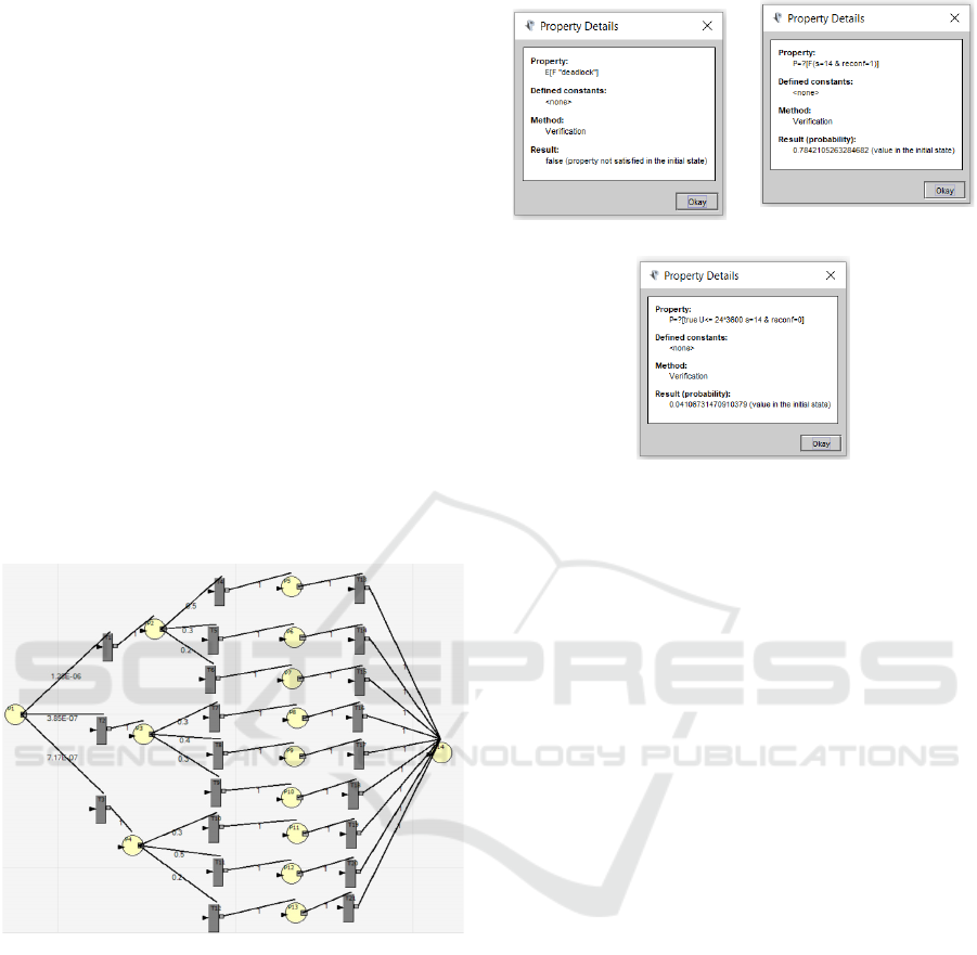
We visualize and analyze the nets, we also simu-
(a) Deadlock property.
(b) Successful reconfigura-
tion.
(c) Failure for one day.
Figure 8: CTL and PCTL properties verification with
PRISM.
late it according to the highest and lowest probabil-
ities. Then, we export the model to PRISM model
checker and verify the following properties as a part
of the analysis: first we verify that the prism model
does not contain any deadlock using this formula
E[F“deadlock”], the result returns false as depicted
in Figure 8a.
Then we verify the probability of success-
ful reconfiguration using this formula P =?[F(s =
14&recon f = 1)], where s = 14 presents the final
state, and recon f presents the reconfiguration result
(0 failed, and 1 successful). The result returns 0.784
as mentioned in Figure 8b. Afterwards, we verify the
probability of failure during one day using the for-
mula P =?[trueU <= 24 ∗ 3600(s = 14&recon f =
0)]. The result returns 0.04 as mentioned in Figure 8c.
The system designers have to consider the obtained
results and decide whether the values are acceptable
or not. Depending on the sensitivity of the considered
system consumers (household, industrial park, health
complexes) a maximal error rate need to be defined to
avoid problems.
5.4 Analysis According to IEC 61499
After having modeled the logic using GR-UML and
after having verified its correctness with formal veri-
fication (ZiZo and PRISM), it is possible now to test
the model in hardware environment. We used the
new ZiZo specifically the component diagram viewer
(see Figure 9) to generate the “.fbt” file of the ex-
ample, then we use 4DIAC to analyze its deploy-
ENASE 2021 - 16th International Conference on Evaluation of Novel Approaches to Software Engineering
228
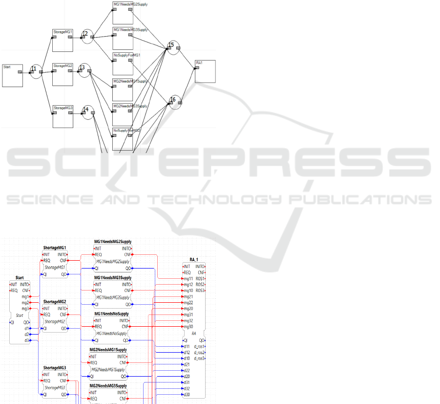
ment. In Figure 9, the component ShortageMG1
(resp. ShortageMG2, ShortageMG3) has the role
of detecting the shortages of mg
1
(resp. mg
2
,
mg
3
). The components having the form of name
MG
i
NeedsMG
j
Supply, have to compare and decide
whether a microgrid mg
i
can be supplied with a mi-
crogrid mg
j
. The final decisions (opening, closing of
switches) are made by the component RA. The inter-
faces are called I
i
with i = 1,...,6. An ongoing link to
I
i
from a component C
j
means that the latter realizes
the interface. An outgoing link from I
i
to a component
C
j
means that the latter requires the interface.
Figure 9: GR-UML:part of the created component diagram.
Figure 10 shows a part of the resulted function
block model in 4DIAC environment. Thanks to Rule
6, the component Start is mapped to a composite
function block having the same name, the rest of the
components likewise.
Figure 10: Part of the generated function blocks model.
5.5 Comparison to Other Works
In comparison to the existing works, our methodology
is more efficient since: (i) it covers more scopes, and
(ii) its concepts are implemented in a software tool.
To the best of our knowledge, all existing method-
ologies are always missing a scope of applications
modelling: (1) There are methods that consider the
function blocks and formal verification but abstract
UML are missing, so these approaches are very tied to
the control and automation level, (2) there are meth-
ods that consider the UML and formal verification,
but function blocks are missing so the advantages of
IEC 61499 (such as the executable models) are not
used, (3) there are methods that consider the UML
and function blocks but here the guarantees about
models correctness are missing. In this paper, a so-
lution that takes advantages from all the mentioned
modeling scopes is provided. Further, the move from
the first phase to the second and third phases are au-
tomated thanks to the new ZiZo version.
6 CONCLUSIONS
This paper proposed a modelling methodology for
reconfigurable distributed control systems. Deal-
ing with reconfigurations in distributed systems is a
complicated task to perform since many constraints
should be taken into account. The proposed method-
ology is introduced to facilitate and improve the mod-
elling stage.
We first introduced a new UML profile, called
GR-UML, for the modelling of probabilistic sys-
tems running under memory and energy constraints.
Thereafter, we defined two sets of transformation
rules responsible for the mapping from GR-UML to
the Petri nets formalism GR-TNCES and the mapping
from GR-UML to IEC 61499 function blocks. The
proposed contributions are implemented in software
tool called ZiZo that allows to edit the new UML pro-
file and to transform it to GR-TNCES and to function
blocks.
Based on these contributions, we built the pro-
posed methodology which consists of three phases:
(1) modelling applications using GR-UML, (2) for-
mal verification of GR-TNCES models obtained from
a transformation of the GR-UML models of the first
phase, and (3) deployment analysis of the function
blocks models obtained from a transformation of the
GR-UML models of the first phase. In this way we
ensure applications clarity from software as well as
control designers/engineers. In future work, we aim
to extend the software tool to enable more output files
Modeling Methodology for Reconfigurable Distributed Systems using Transformations from GR-UML to GR-TNCES and IEC 61499
229

formats readable by other IEC 61499 tools. We plan
also to use the methodology in other DCS applica-
tions such as the airports baggage handling systems.
REFERENCES
Addouche, N., Antoine, C., and Montmain, J. (2006).
Methodology for uml modeling and formal verifica-
tion of real-time systems. In 2006 Int. Conf. on Com-
putational Inteligence for Modelling Control and Au-
tomation and Int. Conf. on Intelligent Agents Web
Technologies and International Commerce, pages 17–
17. IEEE.
Castellanos, E. X., Garcia, C. A., Rosero, C., Sanchez, C.,
and Garcia, M. V. (2017). Enabling an automation
architecture of cpps based on uml combined with iec-
61499. In 17th Int. Conf. on Control, Automation and
Systems, pages 471–476. IEEE.
Dubinin, V., Vyatkin, V., and Pfeiffer, T. (2005). Engineer-
ing of validatable automation systems based on an ex-
tension of uml combined with function blocks of iec
61499. In Proceedings of the 2005 IEEE Int. Conf. on
Robotics and Automation, pages 3996–4001. IEEE.
Fkaier., S., Khalgui., M., and Frey., G. (2020a). Hybrid
context-awareness modelling and reasoning approach
for microgrid’s intelligent control. In Proceedings of
the 15th International Conference on Software Tech-
nologies - Volume 1: ICSOFT,, pages 116–127. IN-
STICC, SciTePress.
Fkaier., S., Khalgui., M., and Frey., G. (2020b). Meta-
model for control applications of microgrids. In 2020
6th IEEE International Energy Conference (ENERGY-
Con), pages 945–950. IEEE.
Fkaier, S., Romdhani, M., Khalgui, M., and Frey, G.
(2016a). Enabling reconfiguration of adaptive control
systems using real-time context-aware framework. In
2016 IEEE/ACS 13th International Conference of
Computer Systems and Applications (AICCSA), pages
1–8. IEEE.
Fkaier, S., Romdhani, M., Khalgui, M., and Frey,
G. (2016b). R2tca: New tool for develop-
ing reconfigurable real-time context-aware frame-
work—application to baggage handling systems. In
Proc. International Conference Mobile Ubiquitous
Comput., Syst., Services Technol.(UBICOMM), pages
113–119.
Fkaier., S., Romdhani., M., Khalgui., M., and Frey., G.
(2017). Context-awareness meta-model for recon-
figurable control systems. In Proceedings of the
12th International Conference on Evaluation of Novel
Approaches to Software Engineering - Volume 1:
ENASE,, pages 226–234. INSTICC, SciTePress.
Hemmati, M., Mohammadi-Ivatloo, B., Abapour, M., and
Anvari-Moghaddam, A. (2020). Optimal chance-
constrained scheduling of reconfigurable microgrids
considering islanding operation constraints. IEEE
Systems Journal.
Hussain, T. and Frey, G. (2007). Defining iec 61499 com-
pliance profiles using uml and ocl. In 2007 5th IEEE
Int. Conf. on Industrial Informatics, volume 2, pages
1157–1162. IEEE.
Jansen, D. N., Hermanns, H., and Katoen, J.-P. (2002). A
probabilistic extension of uml statecharts. In Interna-
tional Symposium on Formal Techniques in Real-Time
and Fault-Tolerant Systems, pages 355–374. Springer.
Khlifi, O., Mosbahi, O., Khalgui, M., and Frey, G. (2015).
Gr-tnces: New extensions of r-tnces for modelling
and verification of flexible systems under energy and
memory constraints. In 2015 10th International Joint
Conference on Software Technologies (ICSOFT), vol-
ume 1, pages 1–8. IEEE.
Miguel-Escrig, O., Romero-P
´
erez, J.-A., Wiesmayr, B.,
and Zoitl, A. (2020). Distributed implementation of
grafcets through iec 61499. In 2020 25th IEEE Int.
Conf. on Emerging Technologies and Factory Automa-
tion, volume 1, pages 402–409. IEEE.
Nokovic, B. and Sekerinski, E. (2013). pstate: A proba-
bilistic statecharts translator. In 2nd Mediterranean
Conference on Embedded Computing, pages 29–32.
IEEE.
Oueslati, R., Mosbahi, O., Khalgui, M., Li, Z., and Qu, T.
(2018). Combining semi-formal and formal methods
for the development of distributed reconfigurable con-
trol systems. IEEE Access, 6:70426–70443.
Panjaitan, S. and Frey, G. (2006a). Combination of uml
modeling and the iec 61499 function block concept for
the development of distributed automation systems.
In 2006 IEEE Conference on Emerging Technologies
and Factory Automation, pages 766–773. IEEE.
Panjaitan, S. and Frey, G. (2006b). Designing
generic/reusable functionality based controllers for
distributed control using uml. In Proceedings 2006
IEEE Int. Conf. on Robotics and Automation, 2006.
ICRA 2006., pages 321–326. IEEE.
Salem, M. O. B., Mosbahi, O., Khalgui, M., and Frey, G.
(2015a). Transformation from r-uml to r-tnces: New
formal solution for verification of flexible control sys-
tems. In 2015 10th International Joint Conference on
Software Technologies (ICSOFT), volume 2, pages 1–
12. IEEE.
Salem, M. O. B., Mosbahi, O., Khalgui, M., and Frey,
G. (2015b). Zizo: Modeling simulation and verifi-
cation of reconfigurable real-time control tasks shar-
ing adaptive resources. In Proc. Int. Conf. Health In-
form.(HEALTHINF), pages 20–31.
Thramboulidis, K. C. (2004). Using uml in control and
automation: a model driven approach. In 2nd IEEE
Int. Conf. on Industrial Informatics, 2004. INDIN’04.
2004, pages 587–593. IEEE.
Tranoris, C. and Thramboulidis, K. (2002). From require-
ments to function block diagrams: a new approach for
the design of industrial control applications. In Pro-
ceedings, 10th Mediterranean conference on control
and automation,(MED2002), Lisbon, Portugal, pages
9–12. Citeseer.
ENASE 2021 - 16th International Conference on Evaluation of Novel Approaches to Software Engineering
230
