
A System Architecture in Multiple Views for an Image Processing
Graphical User Interface
Roberto Wagner Santos Maciel, Michel S. Soares
a
and Daniel Oliveira Dantas
b
Departamento de Computac¸
˜
ao, Universidade Federal de Sergipe, S
˜
ao Crist
´
ov
˜
ao, SE, Brazil
Keywords:
Software Architecture, Unified Modeling Language, 4+1 View Model, UML.
Abstract:
Medical images are important components in modern health institutions, used mainly as a diagnostic support
tool to improve the quality of patient care. Researchers and software developers have difficulty when building
solutions for segmenting, filtering and visualizing medical images due to the learning curve, complexity of in-
stallation and use of image processing tools. VisionGL is an open source library that facilitates programming
through the automatic generation of C++ wrapper code. The wrapper code is responsible for calling paral-
lel image processing functions or shaders on CPUs using OpenCL, and on GPUs using OpenCL, GLSL and
CUDA. An extension to support distributed processing, named VGLGUI, involves the creation of a client with
a workflow editor and a server, capable of executing that workflow. This article presents a description of archi-
tecture in multiple views, using the architectural standard ISO/IEC/IEEE 42010:2011, the 4+1 View Model of
Software Architecture and the Unified Modeling Language (UML), for a visual programming language with
parallel and distributed processing capabilities.
1 INTRODUCTION
Medical images are important components in modern
health institutions, used mainly as a diagnostic sup-
port tool to improve the quality of patient care (Mar-
wan et al., 2017). An advanced medical image
processing and visualization solution offers power-
ful quantitative image reading, ability to evaluate im-
ages in multiple modalities, relevant workflow tools,
several computer-aided diagnostic algorithms, and a
wide range of clinical applications (Ukis et al., 2013).
Examples of computational tools for biomedi-
cal analysis of images are ImageJ, CellProfiler and
Fiji (Morita et al., 2013). TOMAAT is a platform
for researchers and users to share algorithms for
image processing pipelines (Milletari et al., 2019).
CloudMed is a software as a service used by med-
ical institutions for teleconsultation and telediagno-
sis, where healthcare professionals can share medical
images and collaborate through messages (Monteiro
et al., 2012).
There are several challenges in the creation of sys-
tems for processing medical images, such as the size
of the images and the need to integrate with other so-
a
https://orcid.org/0000-0002-7193-5087
b
https://orcid.org/0000-0002-0142-891X
lutions in the clinical and hospital environment (Ukis
et al., 2013; Franc¸a et al., 2017). Most tools do not
allow the sharing of images, software and process-
ing resources. Researchers and programmers find it
difficult to build solutions for segmenting, filtering
and visualizing medical images, due to the learning
curve, complexity of installation and usage of these
tools (Morita et al., 2013).
VisionGL is an open source library that provides
a set of accelerated image processing functions, e.g.,
pixelwise operations, convolution, classical and dif-
fuse mathematical morphology, with dilation, ero-
sion, opening, closing, conditional dilation and ero-
sion and reconstruction. VisionGL facilitates pro-
gramming by automatically generating the C++ wrap-
per code responsible for calling the shaders writ-
ten in OpenCL, compatible with most GPUs and
CPUs (Dantas et al., 2016).
Khoros is a system that automates the develop-
ment of image processing workflows. Khoros’ envi-
ronment is equipped with Cantata, a visual program-
ming language that implements data flows (Gurevich
et al., 2006). Interactive Data Language (IDL) is
a visual programming language that facilitates the
learning of developers and integrates a large number
of functions suitable for treating medical images in
3D (Xiaoqi et al., 2012).
Maciel, R., Soares, M. and Dantas, D.
A System Architecture in Multiple Views for an Image Processing Graphical User Interface.
DOI: 10.5220/0010414602130223
In Proceedings of the 23rd International Conference on Enterprise Information Systems (ICEIS 2021) - Volume 2, pages 213-223
ISBN: 978-989-758-509-8
Copyright
c
2021 by SCITEPRESS – Science and Technology Publications, Lda. All rights reserved
213
Modeling all the concerns of a system’s stakeholders
in a single view is a difficult task. Teams often deal
only with partial and incomplete views of a system,
which are easier to manage (Reineke and Tripakis,
2014). Use of multiple views has been an impor-
tant principle in describing architecture since the first
works in software architecture (Hilliard et al., 2012).
Multiple views documentation helps stakeholders to
better understand the system architecture, and allows
managing complexity and risks during the system de-
velopment (Ribeiro et al., 2017; Franc¸a et al., 2017).
The 4+1 View Model of Software Architec-
ture uses multiple views to separately address the
concerns of the various architectural stakeholders
and address functional and non-functional require-
ments (Kruchten, 1995). An example of architec-
ture that uses this model is found in the study by Vi-
doni (Vidoni and Vecchietti, 2016).
This article presents a description of a graphical
user interface architecture for the VisionGL library,
based on the features of the Khoros-Cantata tool,
in multiple views, using the architectural standard
ISO/IEC/IEEE 42010:2011, the 4+1 View Model of
Software Architecture and the Unified Modeling Lan-
guage - UML.
2 VISUAL PROGRAMMING
LANGUAGES
Khoros-Cantata has features not normally found in
visual programming environments, such as iteration,
control structures, parameters and glyph-based pro-
gramming (Young et al., 1995a). Glyphs provide an
iconic representation of an operator, which can be
connected to another in a visual data stream, with the
possibility of delaying the execution of one glyph un-
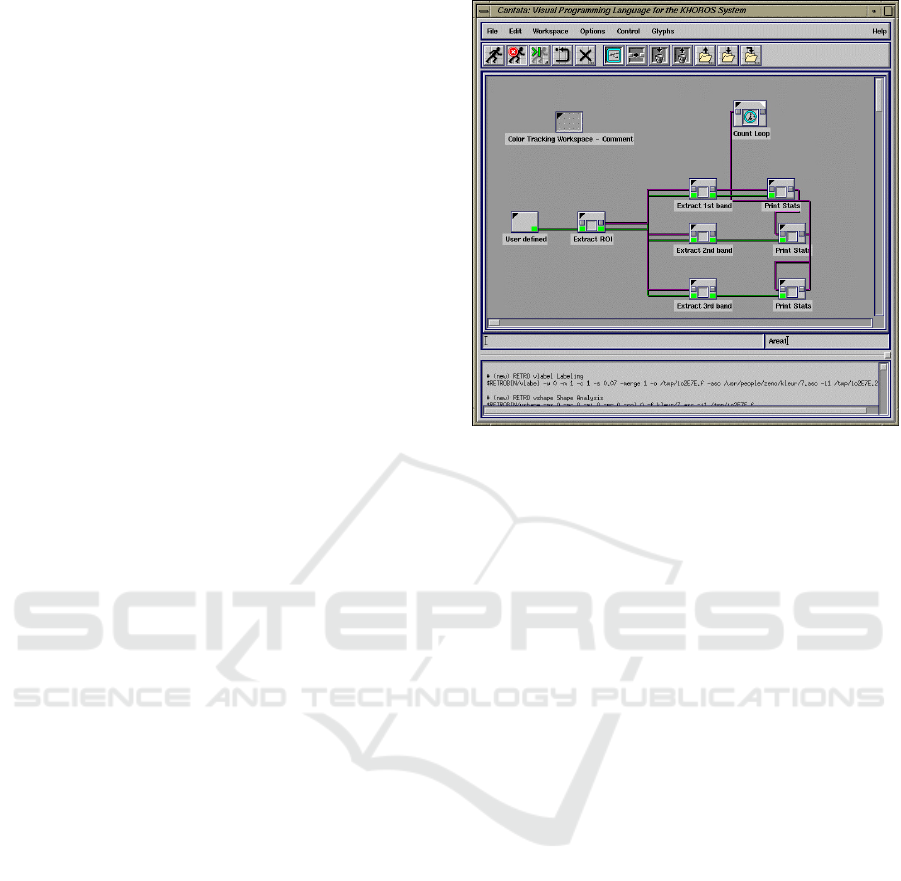
til another one is executed (Young et al., 1995b). Fig-
ure 1 illustrates the Khoros-Cantata development en-
vironment. Cantata is a language whose nodes have
full functions to offer simpler loops in terms of visual
syntax (Johnston et al., 2004).
Processing is an extension of Java with simplified
syntax composed of a programming language, devel-
opment environment and teaching methodology in a
unified structure for learning and prototyping (Reas
and Fry, 2003). Processing can be used as a tool
for writing software sketches, including a custom 2D
/ 3D rendering engine written in pure Java that de-
signs its PostScript and OpenGL feature set (Reas and
Fry, 2004). Pure Data is an open source visual pro-
gramming language used to create programs through
a graphical interface. A “box” represents a certain
function. Boxes are connected with lines that repre-
Figure 1: Khoros-Cantata Environment (Geradts and Bi-
jhold, 1999).
sent the flow of data (Drymonitis, 2015).
Developing effective computer vision algorithms
for specific applications is a challenging task that
requires a significant amount of time invested in
the prototyping phase. Non-programmers are un-
derserved as there is no easy-to-use, high-level in-
terface (Wang and Hogue, 2020). CVNodes is a
high-level abstracted interface that leverages the low-
level power of OpenCV and thus provides access
to general image processing and vision algorithms
based on hierarchical nodes that allow users to create,
drag, drop and connect nodes that implement multi-
ple pre-processing methods to form a pipeline algo-
rithm (Wang and Hogue, 2020).
3 VGLGUI SYSTEM
ARCHITECTURE
The description of the architecture of a system often
makes use of an architectural description language to
organize and express points of view, architectural vi-
sions, the result of applying the point of view to a par-
ticular system that addresses the concerns of its stake-
holders. (ISO, 2011).
UML offers a set of types of diagrams used to doc-
ument views of the user’s functional requirements,
system structure and the dynamic behavior of soft-
ware elements (Sellami et al., 2013). Object-oriented
modeling languages such as UML have been used
to describe software architectures for decades. The
structure of a software can be described, for instance,
ICEIS 2021 - 23rd International Conference on Enterprise Information Systems
214
Table 1: Architecture decision records.
Stakeholder Concern Id Decision Consequence
graduate
students
1 - Easy implementation of workflows j, k Greater difficulty in implementation
2 - Persistence of workflows between sessions a Greater difficulty in implementation
3 - Sharing workflows b Greater difficulty in implementation
4 - Saving the resulting images at the end c Greater difficulty in implementation and security
5 - Using your private data sets d Greater difficulty in implementation and security
6 - Privacy of user data. f Greater difficulty in security
system
administrators
7 - Ease of maintenance e, i Easier maintenance and implementation
8 - Ease of deployment of clients and servers g, l Easier maintenance and deployment
9 - Availability of image processing servers on the Internet f Greater difficulty in security
project
managers
10 - Ease of maintenance e, i Easier maintenance and implementation
11 - Ease of implementation e, h, i Easier maintenance and implementation
image
processing
specialists
12 - Add new functions with ease e Easier maintenance and implementation
by using package diagrams, class diagrams or com-
ponent diagrams, and the interaction between sys-
tem components can be described by sequence dia-
grams (Buchmann et al., 2014).
The description of a software architecture using
the 4+1 View Model consists of five main views. The
logical view, which is the object model of the de-
sign, when an object-oriented design method is used.
The process view, which captures the concurrency
and synchronization aspects of the design. The phys-
ical view, which describes the mapping(s) of the soft-
ware onto the hardware and reflects its distributed
aspect. The development view, which describes the
static organization of the software in its development
environment, and a complementary view of scenar-
ios, which are an abstraction of the most important
requirements (Kruchten, 1995).
VGLGUI allows visual workflow programming
for distributed image processing, through image pro-
cessing functions available in VisionGL library and
image processing functions, available in core and
imgproc modules of OpenCV 4.1.
VGLGUI stakeholders are graduate students, sys-
tem administrators, project managers and image pro-
cessing specialists. Graduate students concerns’ are
the easy implementation of workflows, the persis-
tence of workflows between sessions, the sharing of
workflows, the saving of resulting images at the end,
the use of their private datasets and privacy of user
data. System administrators concerns are the ease of
maintenance and deployment of servers and the avail-
ability of image processing servers on the Internet.
It is a concern of project managers to maintain the
source code easily and of image processing special-
ists to add new functions with ease.
3.1 Architectural Decisions
Architectural description should record the architec-
tural decisions considered essential for the system
of interest (ISO, 2011). Table 1 lists the concerns
of VGLGUI stakeholders with the architectural deci-
sions made for the development of the graphical in-
terface and the consequences of these decisions.
1. VGLGUI Architectural Decision
(a) A database management system (DBMS) or
data serialization technique must be used.
(b) The workflow must have an external represen-
tation in file format so that it can be down-
loaded and shared.
(c) The server must have write access to the file
system.
(d) The system should allow uploading or reading
of files from any file system on the network.
(e) Part of the source code will be generated auto-
matically.
(f) Security through user authentication.
(g) Solution architecture with client, workflow ed-
itor and server.
(h) Scheduling is performed using a first-come,
first-served (FCFS) algorithm.
(i) Only one level of scheduling control on the
client is required and the server does not need
to control switching between CPU and GPU.
(j) There will be a visual workflow editor, which
will be developed using the WebGL (Web
Graphics Library) API, which is a JavaScript
API.
(k) Use of the HTML5 canvas element, which sup-
ports rendering of 2D and 3D graphics.
(l) Development of a web application without the
need for plug-ins in browsers.
A System Architecture in Multiple Views for an Image Processing Graphical User Interface
215
Figure 2: Package diagram.
Figure 3: Class diagram.
3.2 Scenarios of Use
Questions can be asked to understand and document
the context of a software. Answers are captured by
modeling the architecture description as a set of sce-
narios, alternatives and decisions. It is possible to
help stakeholders to informally explore the design
context of a proposed system and its environment and,
in the process, to determine concerns that lead to ar-
chitectural decisions (Harper and Zheng, 2015). In
this section we describe two scenarios of typical us-
age of VGLGUI.
Scenario 1: A graduate student that works with
medical image processing is starting his daily work.
Yesterday he worked on a medical image processing
workflow and today his plan is to finish it. His aim is
to pre-process a batch of a few thousands of images
and save the resulting images to use afterwards. He
loads the unfinished workflow and adds a few oper-
ations. He runs it on a subset of a few images and
visualizes the result on screen. Later, as he is satis-
fied with the results, he decides to apply the workflow
to the whole dataset, saving the resulting images to a
folder while visualizing the output on screen.
ICEIS 2021 - 23rd International Conference on Enterprise Information Systems
216
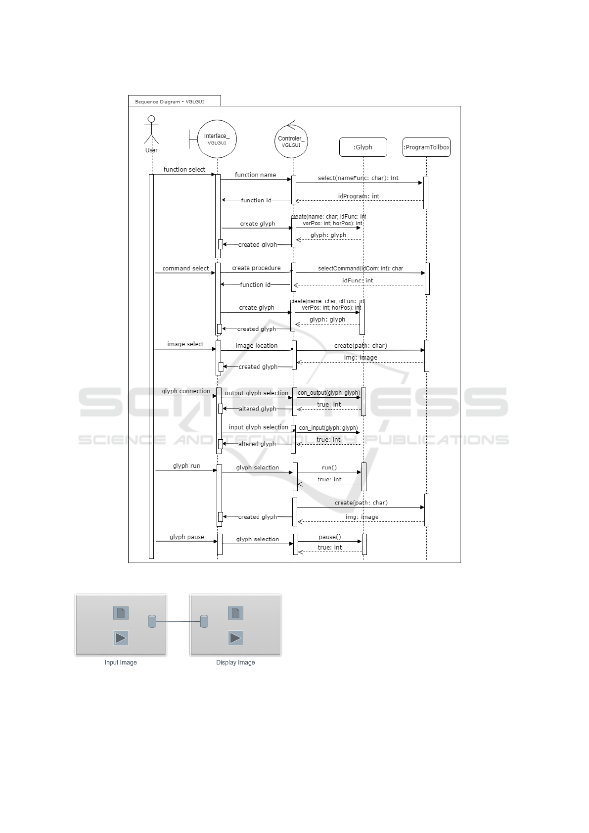
Figure 4: Sequence diagram.
Figure 5: Connections between glyphs.
Scenario 2: A complementary scenario to de-
scribe the architecture considers that the system ad-
ministrator is responsible for the maintenance of a
server with a powerful CPU. Today, he will add a
new GPU to the server and configure the system to
use the GPU. He reconfigures the system and quickly
the users can use the new GPU to run their work-
flows. Later, he receives an email from a user with an
OpenCL shader source code. He places the file in the
appropriate folder and runs a script that updates both
the server and the client binaries. The new binaries
have a new glyph and a new wrapper function, allow-
ing the use of the new shader. He answers the email
A System Architecture in Multiple Views for an Image Processing Graphical User Interface
217

informing that the new function is already available in
the system.
3.3 Logical View
The logical point of view describes the logical struc-
ture of the system in terms of a network of interact-
ing components regardless of technical realization, in
order to achieve maximum reuse and to meet non-
functional requirements (Eder et al., 2017).
The package diagram shows the decomposition of
a given system into cohesive units that are loosely
coupled to each other. Each package can contain the
final, atomic entities, consisting of classes and their
mutual relationships (Tonella and Potrich, 2005).
Figure 2 shows how the elements of the VGLGUI
interface are structured and connected. The Graph-
ical User Interface provides the functionality to cre-
ate, edit, execute and interrupt the execution of vi-
sual image processing files through glyphs. The glyph
is an iconic representation of a function that can be
connected to others forming a data processing flow.
These functions call the functions of VisionGL.
UML class diagrams are used by software engi-
neers to conceptually model the structure of a system
in terms of classes, attributes and operations, and to
express restrictions that must apply to each instance
of the system (Cali et al., 2012). Class diagrams
are widely used in software industry to create a low-
level view of systems development (Fahrenberg et al.,
2014). The classes, with their attributes and meth-
ods, depicts the graphical interface for the VisionGL
library and are illustrated in Figure 3.
The Glyph class represents a functionality of the
VisionGL library to be executed in the image process-
ing workflow. It is possible to configure the param-
eters and assign the input and output images. The
CommandBar class has the methods for creating, edit-
ing, copying, deleting and moving the glyph in the
Workspace. It is possible to run and pause the glyph
and to connect it to another glyph.
The ProgramToolbox class lists VisionGL’s im-
age operations, such as dilation and erosion; control
flow commands, such as procedure creation, condi-
tional structure, creating loops to count executions,
creating loops to perform activities while a condi-
tion is met, establishing the fusion path, interrupting
execution and establishing expressions; and preview
functions for pre-processing and post-processing im-
ages. The users can develop his workflow by selecting
the commands available in the ProgramToolBox.
3.4 Process View
A process is a group of tasks that form an exe-
cutable unit. Processes represent the level at which
the process architecture can be tactically controlled
(i.e., started, recovered, reconfigured, and shut down).
The software is partitioned into a set of independent
tasks. A task is a separate thread of control that can be
scheduled individually on one processing node. The
process architecture can be described at several lev-
els of abstraction, each level addressing different con-
cerns. At the highest level, the process architecture
can be viewed as a set of independently executing
logical networks of communicating programs named
processes (Kruchten, 1995).
The Sequence diagram requires the simultaneous
analysis of restrictions and rules of other diagrams
that hinder its learning. (Alhazmi et al., 2020). Se-
quence diagrams describe a set of processes partially
ordered in send and receive events (Alvin et al.,
2019).
The Sequence diagram illustrated in Figure 4
shows the messages exchanged between the VGLGUI
classes during the prototyping of an image processing
pipeline. In the described scenario it is considered
that the user opened the VGLGUI interface and cre-
ated a workflow file. A workflow is formed by a set of
glyphs connected in a network format to represent the
data flow to be executed. The workflow is persisted in
a physical file.
The GUI has functions for creating, editing, copy-
ing and deleting a workflow file. Methods are im-
plemented for execution, pause, restart execution and
complete cleaning of the workspace contents.
Initially the user selects the VisionGL function
listed by ProgramToolbox that executes the first step
of his program. A graphical representation of this op-
erator is created in the GUI in glyph format. It is be
possible to define parameters for the operator to per-
form his action. To do that, the user must click on
the glyph Argument button, a dialog box opens for
editing the parameter. Then, the user selects from
ProgramToolBox the necessary flow controls com-
mands for assembling the programming logic. A
graphic representation of the command is created in
the GUI in glyph format.
The user indicates the image path for processing.
A glyph that represents the image is created in the
GUI without the input connection because it only pro-
vides information to other glyphs.
The developer performs successively the selection
and connection of glyphs to assemble its program-
ming logic. For the connection of two glyphs it is
necessary to click on the data connection of the first
ICEIS 2021 - 23rd International Conference on Enterprise Information Systems
218
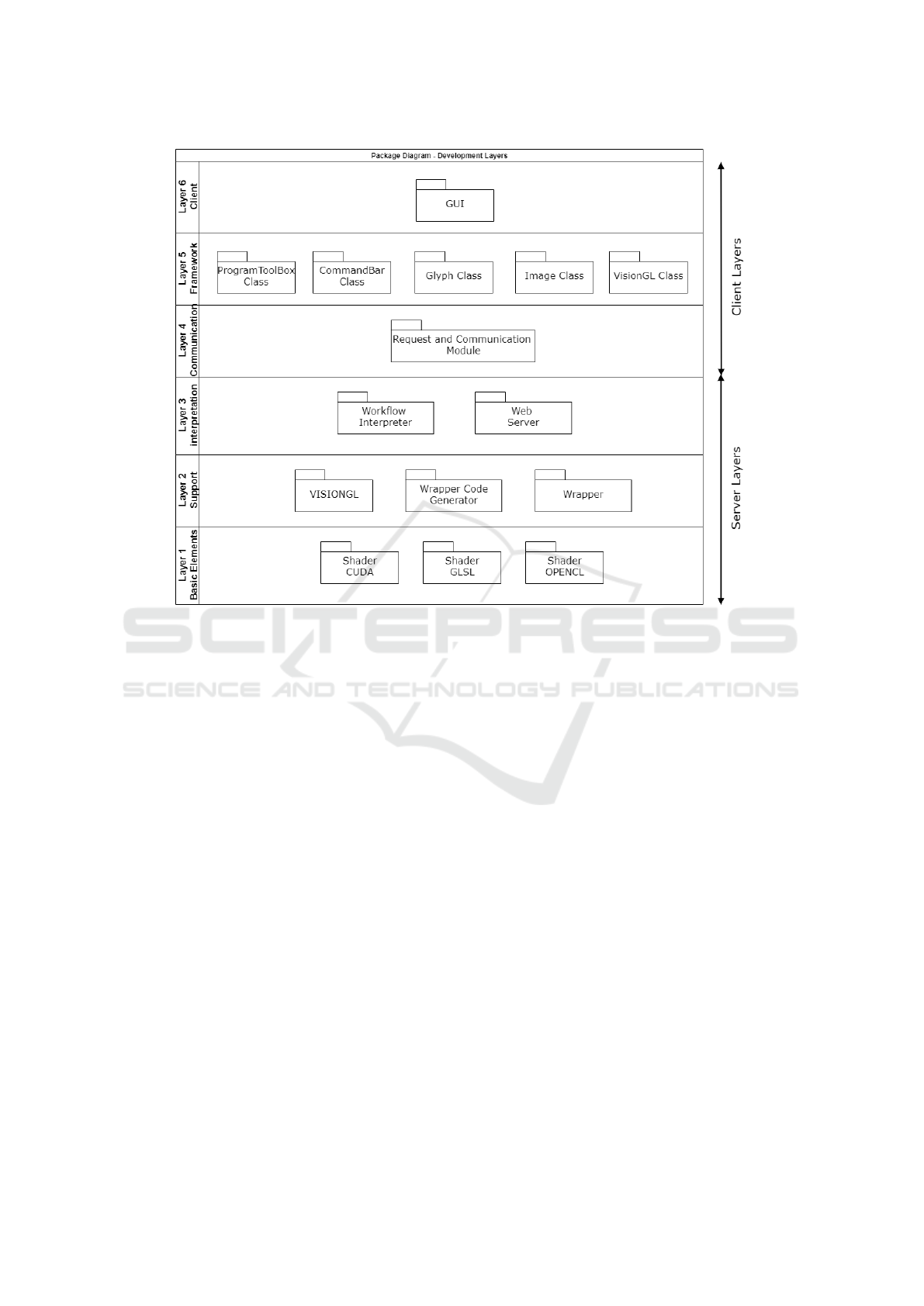
Figure 6: Package diagram - development layers.
glyph and then click on the connection of the second
glyph, a connection line is established. The glyph
connection event is shown in the Sequence diagram.
The connection between glyphs is illustrated in Fig-
ure 5.
Execution of the operator is triggered by click-
ing on its “Run” button, glyph run event of the Se-
quence diagram. It is possible to run a single glyph
or an entire program. It is possible to pause the exe-
cution of a glyph. The glyph pause event is shown
in the Sequence diagram. An error message is dis-
played in the console when there is a problem with
the execution of an operator. Glyphs that are intended
to provide data to other glyphs do not have a “Run”
button.
At the end of the execution of the workflow, the
resulting images can be saved to files.
3.5 Development View
The development view of the architecture focuses on
the organization on the software development envi-
ronment. The software is packaged in small chunks
— program libraries, or subsystems — that can be
developed by one or a small number of developers.
The subsystems are organized in a hierarchy of lay-
ers, each layer providing a narrow and well-defined
interface to the layers above it (Kruchten, 1995).
Figure 6 represents the 6 layers required for the
operation of VGLGUI. Layers 4, 5 and 6 run on the
client and layers 1, 2 and 3 run on the server. Layer 6
- Client, communicates with the Web to allow editing
and execution of the workflow. Layer 5 - Framework,
provides the functionality of the interface. Layer 4 -
Communication, is responsible for requests and other
communications with the server. Layer 3 - Interpre-
tation, has a workflow interpreter and a web server.
Layer 2 - Support, provides resources for creating op-
erators. Layer 1 - Basic Elements, contains the oper-
ators that perform the workflow.
While software components comprise relatively
large parts of systems, applications can easily con-
sist of hundreds of strongly interconnected compo-
nents (Holy and Brada, 2011). The component di-
agram is a high-level abstraction model with useful
information for understanding the architecture of a
system, as it describes the execution units, data stor-
age and interaction mechanisms (Haitzer and Zdun,
2013). VGLGUI has the GUI, Glyph and VisionGL
components, illustrated in Figure 7.
The GUI component consists of a workspace, a
main menu, a command bar, a program toolbox and
A System Architecture in Multiple Views for an Image Processing Graphical User Interface
219
Figure 7: Component diagram.
Figure 8: Glyph components.
console. The main menu is located at the top of the
screen and groups functions to manipulate files, edit
workflows and configure the GUI. The command bar
appears just below the Menu and gives one easy ac-
cess to the most frequently used features. The pro-
gram toolbox has a shader collection, functions for
the programmer to use in the construction of the im-
age processing workflow. The console displays mes-
sages about workflow processing.
A glyph is a visual representation of a function
available on VGLGUI for the development of image
processing workflows. Components of the glyph are
the operator name; the input data connection, used for
ICEIS 2021 - 23rd International Conference on Enterprise Information Systems
220
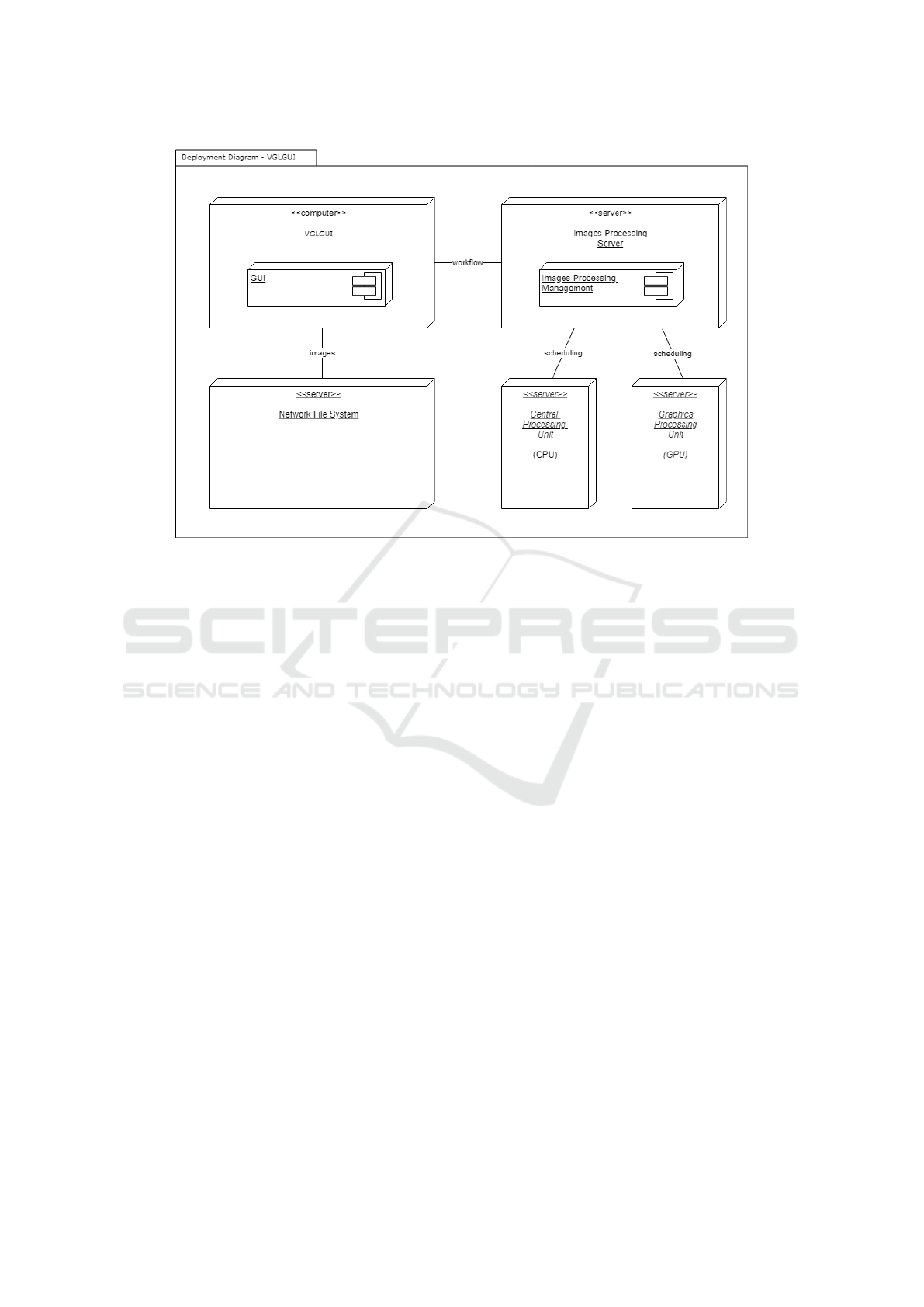
Figure 9: Deployment diagram.
data entry; output data connection, used for data out-
put; argument button, used to specify parameters val-
ues for the operator; and the run button, used to run
the function. The components of the glyph are illus-
trated in Figure 8.
VisionGL library has a data structure named
vglImage that has pointers to the images stored in
each supported context, which are RAM, OpenCL,
CUDA and GLSL (Dantas et al., 2015). Images are
supported with two, three and more dimensions, with
one, three and four channels (Dantas et al., 2016). The
library has a script that generates the wrapper code
with the API calls necessary before calling the shader.
This wrapper code is written in C++.
3.6 Physical View
The physical architecture takes into account primarily
the non-functional requirements of the system such as
availability, reliability, performance, and scalability.
The software executes on a network of computers, or
processing nodes (Kruchten, 1995). The UML De-
ployment diagram is used to model the static deploy-
ment of a system, showing a configuration of the con-
stituent components of an infrastructure portfolio (In-
galsbe, 2005). The physical architectural organization
on which VGLGUI is implemented and executed in
terms of technologies for connecting its elements and
data traffic is described in this section and illustrated
in Figure 9.
The VisionGL library supports parallel process-
ing on CPUs using OpenCL, and on GPUs using
OpenCL, GLSL and CUDA. An extension to sup-
port distributed processing, named VGLGUI, in-
volves creating a client and workflow editor and a
server, capable of executing that workflow.
Automatic source code is generated to create new
image processing operators, both on the client and on
the server. In order to run the workflow, the client
sends a list of input file names available in some path
of a Network File System (NFS) to a server. If the
number of images is very large, then the client allo-
cates a subset of images to each server.
Scheduling is performed using a first-come, first-
served (FCFS) algorithm. Servers are configurable,
able to use only the CPU or the GPU. Machines with
discrete GPU (separate from the processor) run two
instances of the server, one associated with the CPU
and the other with the GPU. Therefore, only one level
of scheduling control on the client is needed and the
server does not need to control the switching between
CPU and GPU.
The development is carried out with the WebGL
API, which is a JavaScript API, available from the
HTML5 canvas element, which offers support for ren-
dering 2D graphics and 3D graphics, implemented in
a web application without the need for plug-ins in
browsers.
A System Architecture in Multiple Views for an Image Processing Graphical User Interface
221

4 CONCLUSIONS
Researchers and programmers find it difficult to pro-
totype image processing pipeline. The VisionGL li-
brary facilitates programming with parallel process-
ing functions. A system architectural description
is presented for the development of the VGLGUI
graphical interface that supports distributed process-
ing through the creation of a workflow editor client
and a server, capable of executing this workflow. Two
scenarios were presented, with graduate students and
system administrators as stakeholders.
The logical view is described by the package
diagram, which represents the subsystems of the
VGLGUI interface, and by the class diagram, which
defines the system classes. The process view is de-
tailed by a sequence diagram, which describes the
temporal order in which messages are exchanged be-
tween the objects involved in the process of creating
and executing a visual program. The development
view is illustrated by the components diagram, which
represents the components as modules and libraries of
the system. The physical view is represented by the
deployment diagram, which determines the physical
architecture in which the system should be deployed.
As for future work we will develop the graphical
interface VGLGUI. We may also develop a reference
architecture for medical image processing systems.
REFERENCES
Alhazmi, S., Thevathayan, C., and Hamilton, M. (2020). In-
teractive pedagogical agents for learning sequence di-
agrams. In Artificial Intelligence in Education, pages
10–14. Springer.
Alvin, C., Peterson, B., and Mukhopadhyay, S. (2019).
Static generation of UML sequence diagrams. In-
ternational Journal on Software Tools for Technology
Transfer, 23:31–53.
Buchmann, T., Dotor, A., and Westfechtel, B. (2014).
Model-driven software engineering: concepts and
tools for modeling-in-the-large with package dia-
grams. Computer Science – Research and Develop-
ment, 29(1):73–93.
Cali, A., Gottlob, G., Orsi, G., and Pieris, A. (2012). Query-
ing UML class diagrams. In International Confer-
ence on Foundations of Software Science and Com-
putational Structures FoSSaCS, pages 1–25. Springer.
Dantas, D. O., Leal, H. D. P., and Sousa, D. O. B. (2015).
Fast 2D and 3D image processing with OpenCL. In
International Conference on Image Processing ICIP,
pages 4858–4862. IEEE.
Dantas, D. O., Leal, H. D. P., and Sousa, D. O. B.
(2016). Fast multidimensional image processing with
OpenCL. In International Conference on Image Pro-
cessing ICIP, pages 1779–1783. IEEE.
Drymonitis, A. (2015). Introduction to pure data. In Digital
Electronics for Musicians, pages 1–50. Apress.
Eder, J., Zverlov, S., Khalil, M., and Ipatiov, A. (2017).
Bringing DSE to life: exploring the design space of an
industrial automotive use case. In 20th International
Conference on Model Driven Engineering Languages
and Systems MODELS, pages 270–280. IEEE.
Fahrenberg, U., Acher, M., Legay, A., and Wasowski, A.
(2014). Sound merging and differencing for class di-
agrams. In International Conference on Fundamental
Approaches to Software Engineering FASE, pages 63–
78. Springer.
Franc¸a, J. M. S., de S. Lima, J., and Soares, M. S. (2017).
Development of an Electronic Health Record Appli-
cation using a Multiple View Service Oriented Archi-
tecture. In Proceedings of the 19th International Con-
ference on Enterprise Information Systems - Volume
2, ICEIS, pages 308–315. INSTICC, SciTePress.
Geradts, Z. and Bijhold, J. (1999). Forensic video inves-
tigation with real-time digitized uncompressed video
image sequences. In Investigation and Forensic Sci-
ence Technologies, pages 154–164. SPIE.
Gurevich, I. B., Khilkov, A. V., Koryabkina, I. V.,
Murashov, D. M., and Trusova, Y. O. (2006). An
open general-purposes research system for automat-
ing the development and application of information
technologies in the area of image processing, analysis
and evaluation. Pattern Recognition and Image Anal-
ysis, 16(4):530–563.
Haitzer, T. and Zdun, U. (2013). Controlled experiment
on the supportive effect of architectural component
diagrams for design understanding of novice archi-
tects. In European Conference on Software Architec-
ture ECSA, pages 54–71. Springer.
Harper, K. E. and Zheng, J. (2015). Exploring software ar-
chitecture context. In 12th Working IEEE/IFIP Con-
ference on Software Architecture WICSA, pages 123–
126. IEEE.
Hilliard, R., Malavolta, I., Muccini, H., and Pelliccione,
P. (2012). On the composition and reuse of view-
points across architecture frameworks. In Joint Work-
ing Conference on Software Architecture & 6th Eu-
ropean Conference on Software Architecture, pages
131–140. IEEE.
Holy, L. and Brada, P. (2011). Viewport for component di-
agrams. In International Symposium on Graph Draw-
ing GD, pages 443–444. Springer.
Ingalsbe, J. A. (2005). Supporting the building and analysis
of an infrastructure portfolio using UML deployment
diagrams. In International Conference on the Unified
Modeling Language UML, page 105–117. Springer.
ISO (2011). ISO/IEC/IEEE Systems and software engineer-
ing – Architecture description.
Johnston, W. M., Hanna, J. R. P., and Millar, R. J. (2004).
Advances in dataflow programming languages. ACM
Computing Surveys, 36(1).
Kruchten, P. (1995). Architectural blueprints—the “4+1”
view model of software architecture. IEEE Software,
12(6):42–50.
ICEIS 2021 - 23rd International Conference on Enterprise Information Systems
222

Marwan, M., Kartit, A., and Ouahmane, H. (2017). Using
cloud solution for medical image processing: Issues
and implementation efforts. In 3rd International Con-
ference of Cloud Computing Technologies and Appli-
cations CloudTech, pages 1–7. IEEE.
Milletari, F., Frei, J., Aboulatta, M., Vivar, G., and Ahmadi,
S.-A. (2019). Cloud deployment of high-resolution
medical image analysis with TOMAAT. Journal of
Biomedical and Health Informatics, 23(3):969–977.
Monteiro, E. J. M., Silva, L. A. B., and Costa, C. (2012).
CloudMed: Promoting telemedicine processes over
the cloud. In 7th Iberian Conference on Information
Systems and Technologies, pages 1–6. IEEE.
Morita, M., Tawara, T., Nishimura, M., Yoshizawa, S.,
Chou, B., Kuroki, I., Ijiri, T., Tsujimura, Y., Himeno,
R., and Yokota, H. (2013). Biomedical image com-
munication platform. In First International Sympo-
sium on Computing and Networking, pages 281–287.
IEEE.
Reas, C. and Fry, B. (2003). Processing: A learning en-
vironment for creating interactive web graphics. In
SIGGRAPH Web Graphics. ACM.
Reas, C. and Fry, B. (2004). Processing.org: Programming
for artists and designers. In SIGGRAPH Web Graph-
ics. ACM.
Reineke, J. and Tripakis, S. (2014). Basic problems
in multi-view modeling. Tools and Algorithms for
the Construction and Analysis of Systems TACAS,
18(3):1577–1611.
Ribeiro, Q. A. D. S., Ribeiro, F. G. C., and Soares, M. S.
(2017). A technique to architect real-time embed-
ded systems with SysML and UML through multiple
views. In Proceedings of the 19th International Con-
ference on Enterprise Information Systems - Volume
2, ICEIS, pages 287–294. INSTICC, SciTePress.
Sellami, A., Haoues, M., and Ben-Abdallah, H. (2013).
Automated COSMIC-based analysis and consistency
verification of UML activity and component dia-
grams. In Evaluation of Novel Approaches to Soft-
ware Engineering ENASE, volume 417, pages 48–63.
Springer.
Tonella, P. and Potrich, A. (2005). Package diagram. In
Reverse Engineering of Object Oriented Code, pages
133–154. Springer.
Ukis, V., Balachandran, B., Rajamani, S. T., and Friese, T.
(2013). Architecture of cloud-based advanced medical
image visualization solution. In International Con-
ference on Cloud Computing in Emerging Markets,
pages 1–5. IEEE.
Vidoni, M. and Vecchietti, A. (2016). Towards a Refer-
ence Architecture for Advanced Planning Systems. In
Proceedings of the 18th International Conference on
Enterprise Information Systems - Volume 1: ICEIS,,
pages 433–440. INSTICC, SciTePress.
Wang, J. and Hogue, A. (2020). CVNodes: A visual pro-
gramming paradigm for developing computer vision
algorithms. In 17th Conference on Computer and
Robot Vision (CRV), pages 174–181. IEEE.
Xiaoqi, L., Xin, L., and Dongzheng, J. (2012). Research
and implement of three-dimensional reconstruction
technology for medical images based on IDL. In In-
ternational Conference on Computer Science and Ser-
vice System, pages 2317–2321. IEEE.
Young, M., Argiro, D., and Kubica, S. (1995a). Cantata:
Visual programming environment for the Khoros sys-
tem. SIGGRAPH Computer Graphics, 29(2):22–24.
Young, M., Argiro, D., and Worley, J. (1995b). An object
oriented visual programming language toolkit. SIG-
GRAPH Computer Graphics, 29(2):25–28.
A System Architecture in Multiple Views for an Image Processing Graphical User Interface
223
