
A Virtual Environment Software to Position Corner Reflectors for
Assisting in SAR Sensor Calibration
Tak Wing Li and Raffaella Guida
Surrey Space Centre, University of Surrey, Guildford, U.K.
Keywords: Remote Sensing, Virtual Reality, Unity, Software, Satellite, SAR, Corner Reflector, Calibration, Coding,
Radar Cross Section.
Abstract: Synthetic aperture radars (SAR) have been used for decades to observe activity and changes on the Earth’s
surface. This type of satellite imaging can be used under any weather and light condition as it does not depend
on the Sun’s illumination and is not obstructed by clouds, water vapours, etc. As any other instrument, SAR
systems need to be calibrated. External calibration can be applied, for example, to SAR sensors on spaceborne
platforms. In this case, an external target point, such as a corner reflector (CR) is placed in the location of
imaging and its Radar Cross Section (RCS), the physical property measured by SARs, is recorded with the
final aim of comparing it with its expected theoretical value and calculate then the calibration constant.
Deploying a CR correctly requires experience and knowledge of theoretical conditions to maximize its RCS
(that range from the selection of the site and shape of the CR to specific values for the azimuth and elevation
angles). In this paper, a Virtual Reality (VR) environment has been developed in Unity to assist students/users
in visualising the process mentioned above and being able to find the optimal CR orientation and placement.
The program currently works with SAR data from the Copernicus constellation
1 INTRODUCTION
Earth observation with satellites, and its teaching in
university classes, is becoming more popular,
especially when accomplished with Synthetic
Aperture Radar (SAR). SAR can penetrate through
most clouds, precipitation and in some cases, dense
vegetation canopy (Molthan, Bell & Schultz, 2017).
SAR images require calibration in the majority of
applications in order to relate the digital number in
the image to the physical property measured which is
the signal backscattered from the scene under study.
There are a few methods for calibrating the sensors,
like internal and external calibration (Freeman, 1992).
This paper will focus on external calibration and how
virtual reality can support its teaching.
External calibration is normally performed by
using target points, such as corner reflectors (CR).
These can be positioned at the desired location and
with specific orientation to increase the backscattered
signal. Given the dimensions of CRs and the need of
moving them around, deploying such objects is not an
easy task.
Normally, external calibration requires a survey
of places where the CR would be deployed. If the
planning is inaccurate, i.e. the type of corner reflector
is inefficient or the angle of placement is off, then the
whole calibration might be unsuccessful. To offer
remote sensing students an opportunity to get
acquainted with external calibration of SARs, a
Virtual Reality (VR) program has been developed and
is here presented. Based in Unity, the program
simulates the activity of positioning corner reflectors
and calculate the best setup for the optimal results.
By using such program, the planning can be
preliminarily handled which is more advantageous
compared to practical work since it allows for
constant readjustment of the results to find the most
efficient setup before the mere deployment is needed.
Of the different types of VR (Matthews, 2020), this
paper deals with the non-immersive type.
The paper is organized as follows: Section 2
presents the background and the theory behind SAR
calibration; Section 3 will detail the VR environment
developed in Unity and the benefits to the user before
Conclusions can be drawn.
Li, T. and Guida, R.
A Virtual Environment Software to Position Corner Reflectors for Assisting in SAR Sensor Calibration.
DOI: 10.5220/0010404401770183
In Proceedings of the 13th International Conference on Computer Supported Education (CSEDU 2021) - Volume 2, pages 177-183
ISBN: 978-989-758-502-9
Copyright
c
2021 by SCITEPRESS – Science and Technology Publications, Lda. All rights reserved
177

2 BACKGROUND AND THEORY
To better understand the VR environment presented
in Section 3, it is necessary to introduce some topics
such as SAR sensor calibration and the radar cross
section. A subsection explaining reasons in favour for
an adoption of VR in learning environment is also
provided.
2.1 SAR Calibration
There are different types of SAR calibration and, in
the following, the “external” one is covered. With the
latter, the echo signal expected by a SAR system (the
Radar Cross Section) for a target of known
characteristics is compared with a real measurement
or, better, with the Digital Number (DN) of the pixels
corresponding to the position of the known target.
From this comparison, the calibration constant is
calculated and applied to any other pixel in the image.
The external calibration requires deployment of such
structures with known characteristics, called Corner
Reflectors, which are described in the following
section.
2.2 Corner Reflectors and Radar Cross
Section Measurement
The main reason for using corner reflectors is for their
high reflectivity against electromagnetic (EM) waves.
To determine how bright a corner reflector
appears in the image, it is important to consider the
radar cross section (RCS). The typical measurement
of brightness within a SAR image, the backscattering
coefficient “Sigma Nought”, is equal to the RCS (in
dBm
2
) normalised to the area A of the illuminated
resolution cell (Freeman, 1992):
𝜎
=
<𝜎
>
𝐴
(1)
where 𝜎
= normalised RCS, 𝜎
= RCS of nth RCS
measurement with <> denoting the ensemble average,
A = illuminated area (projected onto the ground).
𝐴
=
𝑝
𝑝
𝑠𝑖𝑛𝜃
(2)
𝑝
,𝑝
= SAR image pixel dimensions in the azimuth
and slant range directions, respectively.
𝜃
= local incidence angle at the scattering surface.
In ideal conditions, the SAR image is fully
described by its scattering matrix element in complex
representation, S
pq
, with p describing the transmit
polarization and q the receiving one, or the same but
in intensity representation through the RCS as the
equations below show (Freeman, 1992):
𝐸
𝐸
=
𝑒
𝑅
𝑆
𝑆
𝑆
𝑆
𝐸
𝐸
(3)
𝜎
=4𝜋𝑆
(4)
with 𝜎
= non-normalised RCS,
= scattered
electric field, 𝑘
= wave number, R = radial distance
between scatterer and radar antenna,
= incident
electric field, and h and v subscripts denoting the
horizontal and vertical polarisations, respectively.
The RCS of the target would need to be much
larger than its surrounding area, as the surfaces
nearby will be made of non-zero radar backscatterers.
It is also important for the targets to coherently
interact as little as possible with the terrain, at the
same time maintaining wide and stable RCS patterns.
For calibration, it is most common to use trihedral
corner reflectors as they are one of the most optimal
shapes to achieve the conditions above and the RCS
pattern has a 3 dB beamwidth of approximately 40°
in the azimuth orientation. The size of these reflectors
also depends on the frequency bands of the radar,
with lower frequencies requiring larger CRs. This
project will focus on data from the Sentinel-1B which
carrier is in C-Band, around 5GHz.
For the program, the selected target reflectors
were the triangular, square, and circular trihedral
corner reflectors. The approximate expression for a
triangular CR is given in Eq. (5):
𝜎
𝜃,𝜓
≈
𝑎
×
𝑐𝑜𝑠𝜃 + 𝑠𝑖𝑛𝜃
𝑠𝑖𝑛𝜓 +
𝑐𝑜𝑠𝜓
−2×
𝑐𝑜𝑠𝜃+ 𝑠𝑖𝑛𝜃
𝑠𝑖𝑛𝜓 + 𝑐𝑜𝑠𝜓
(5)
Where a = inner edge length of trihedral CR, 𝜃 =
azimuth angle of CR relative to radar direction, 𝜓 =
elevation angle of CR relative to radar direction.
The theoretical maximum RCS equations of each
shape is given below in Eq. (6), (7), (8).
𝜎
=
(6)
𝜎
=
12𝜋𝑎
𝜆
(7)
𝜎
=
0.507𝜋
𝑎
𝜆
(8)
CSEDU 2021 - 13th International Conference on Computer Supported Education
178

The RCS of the square CR is the highest and is a
factor of 9 greater than the triangular CR, and the
circular CR is a factor of 3.8 greater than the
triangular CR.
2.3 Virtual Reality in Academic
Learning and Training
At the present day, there are five main categories of
virtual reality (Sultan, 2020):
1. Non-immersive
2. Fully Immersive
3. Semi-Immersive
4. Augmented Reality
5. Collaborative VR
The program described in this paper is based on
non-immersive VR that can be commonly found in
most daily devices. This type of VR refers to an
environment within which users can interact with the
characters, objects, or the scene itself. This VR does
not involve wearing any equipment to immerse the
user into the virtual world. For instance, any gaming
devices such as Xbox, PlayStation, computers, or
mobile phones would use this type of VR. This kind
of VR well suits also the calibration task previously
described as it is conceived for a Windows Operating
System computer.
Many studies investigated the benefits of virtual
reality in education and training. For example, in
Pantelidis (2009) it was found that:
1. Immersive VR provide first-person experiences
that are specifically designed to help students learn
material which cannot be obtained in any other way
in formal education.
2. This experience makes up the bulk of our daily
interaction with the world, although schools promote
third-person experiences.
3. “The convergence of theories of knowledge
construction with VR technology permits learning to
be boosted by the manipulation of the relative size of
objects in virtual worlds, by the transduction of
otherwise imperceptible sources of information, and
by the reification of abstract ideas that have so far
defied representation.”
According to Hu Au & Lee (2017), often students
consider classroom-based learning irrelevant and find
that there is a disconnection between theory learnt in
the class and practical work done in the real world.
However, VR provides the bridge between these two
areas and help promote student satisfaction and
engagement. By increasing these factors, the
student’s learning and personal development is
further increased (Hu Au & Lee, 2017). Another
important advantage of using VR is to give student a
sense of identity. For example, virtual fieldtrips could
inspire a student to head into a STEM or a medical
career by showing the workplace and job roles in a
first-person experience (Hu Au & Lee, 2017). To
further enhance the experience, students can be
placed into fully immersive VR or use augmented
reality (AR). As shown later, the VR environment
here presented can be advantageous to students
studying a course in satellite remote sensing as would
enable a better understanding of SAR sensor
calibration and corner reflector deployment, without
the need to engage in field surveys.
To sum up, the quality of the education can be
improved due to the more accurate illustration of
certain features, processes, and so forth. VR allows
close examination of certain objects in the virtual
environment and provides complete safety than if it
would be conducted in a real world. This can build up
the students’ strengths and decrease their weaknesses.
VR allows anyone to participate due to its flexible
setup. It enables users to create anything from their
imagination and allows easy visualisation and
manipulations of objects to grasp difficult concepts
(Hu Au & Lee, 2017).
3 DEVELOPING THE PROGRAM
ON UNITY
In this section, a brief explanation of the program will
be provided.
Overall, the program has three main scenes: The
start menu, the virtual Earth environment and the
virtual landscape at the surface. Briefly, the start
menu will allow users to select their desired satellite
data. The second scene will allow the user to get a
visual of the geographic area where the data is
acquired from, along with the flight direction of the
satellite. The last scene will allow the user to be on a
virtual surface to choose the corner reflector shape,
size, orientation, and place it onto the ground, with
the resulting values of RCS being displayed.
3.1 Scene 1: Start Menu
Right at the beginning of the program, a start menu
scene is shown to allow the user to select the satellite
metadata they are interested in. An ‘Open File’ button
opens the file explorer on the user’s personal
computer.
For the current version of the program,
A Virtual Environment Software to Position Corner Reflectors for Assisting in SAR Sensor Calibration
179
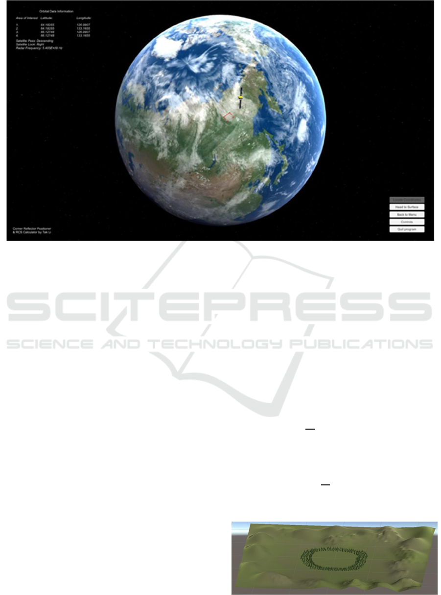
Figure 1: Scene 2 - Virtual Earth scene from space, once "Locate Coordinates" button is pressed.
only Sentinel-1B data, from the European Copernicus
constellation, has been tested in the development and
the metadata can be found in the ‘/Products’ folder as
a file type of ‘.xml’.
In an XML file, there are many parent nodes and
children nodes which carry the relevant information.
Therefore, it is necessary to write a script that allows
the XML file to be efficiently read and extract data
from the useful nodes.
Once the file is selected, the “Start” button can be
pressed to simultaneously read the file and to
transition onto the next scene.
3.2 Scene 2: Virtual Earth from Space
The second scene that appears is the virtual
environment of the Earth as seen from space (shown
in figure 1). In this scene, the user gets a visual
representation of the geographical location from
which the satellite captured an image. The relevant
information it gives are the following: the coordinates
of the area, the direction of ascendance of the satellite,
the side it is looking at and the radar frequency.
Since the information is based on Sentinel-1B
data, it will always be side-looking right. The primary
script for this scene is locating the coordinates on
Earth itself. This involved taking the saved data from
scene 1 and transforming it from latitude and
longitude to ECEF (Earth-centred earth-fixed
reference frame). The reason for this is because
plotting using ECEF points would line up with the
Unity coordinate system which also uses X, Y and Z
coordinates.
It was found that the general equations (shown Eq.
9-11) to convert GPS coordinates to Cartesian
coordinates would result in different outputs
compared to what was expected.
𝑥=
𝑅
+ℎ
𝑐𝑜𝑠𝜙𝑐𝑜𝑠𝜆
(9)
𝑦=
𝑅
+ℎ
𝑐𝑜𝑠𝜙𝑠𝑖𝑛𝜆 (10)
𝑧=
𝑏
𝑎
𝑅
+ℎ𝑠𝑖𝑛𝜙 (11)
Where R
E
is the radius of the Earth, h is the
geographic height above the surface, ϕ is the latitude,
λ is the longitude and
is equal to 1-e
2
, where e is
the eccentricity of the Earth, assumed to be zero in
this program. The height is also assumed to be zero.
Figure 2: Terrain seen from afar.
CSEDU 2021 - 13th International Conference on Computer Supported Education
180

Another solution was found by a Unity user online
(mgear, 2016), where the sine and cosine functions
were switched around. The Y and Z coordinates were
also swapped to correspond to the Unity world
coordinates. The new equations created are the
following:
𝑥=𝑅
𝑠𝑖𝑛𝜙𝑐𝑜𝑠𝜆 (12)
𝑦=𝑅
𝑠𝑖𝑛𝜙𝑠𝑖𝑛𝜆 (13)
𝑧=𝑅
𝑐𝑜𝑠𝜙 (14)
3.3 Scene 3: Virtual Earth Surface to
Place Corner Reflectors
The last scene for the program is the most important
one. It provides the user the ability to move around in
the virtual environment and place the corner
reflectors. Although it must be noted that the
environment does not match the actual geographical
location which the satellite captures and is an open
flat plain terrain with trees and hills. The terrain was
generated with Unity’s Terrain generator. This lets
the developer to easily create an open virtual world
by allowing the raise and descend of the ground to
create hills or holes. It also allows mass placement of
trees models. As seen in figure 2, the terrain does not
expand infinitely but is a large square-shaped
generated land.
The user interface, shown in figure 3, gives
multiple options for the setup. This includes a
dropdown menu to select the shape for the CR, the
inner edge length, and the azimuth and elevation
angle of the CR relative to the boresight of the radar.
The flight direction and incidence angle has been
visualised in the figure 3. Students can get an idea of
how the electromagnetic waves are beamed to the
surface and towards the CR. The orbital positions of
the satellite were given in ECEF coordinates;
therefore, it was necessary to convert it to an ENU
(East-North-Up) coordinates to project the flight
direction onto the surface (figure 4).
3.3.1 Assumptions
As shown in figure 2, the ground is assumed for now
to be perfectly flat. If someone were to replicate
results given from the simulation, the user should also
find ground as flat as possible at the location. The
other assumption is that the satellite incidence angle
is equal at all positions within the landscape and uses
the mid swath incidence angle from the orbital data.
It will later be explained in the future works section
how the results can be more accurate.
3.3.2 ECEF to ENU Conversion
To convert ECEF to ENU coordinates, the following
transformation is applied (Subirana, Zornoza &
Hernández-Pajares, 2011):
𝐸
𝑁
𝑈
=𝑹
𝟏
𝜋/2 − 𝜓
𝑹
𝟑
𝜋/2 +𝜆
𝑥
𝑦
𝑧
(15)
𝑹
𝟏
𝜋/2 − 𝜓
𝑹
𝟑
𝜋/2 + 𝜆
=
−𝑠𝑖𝑛𝜆 𝑐𝑜𝑠𝜆 0
−𝑐𝑜𝑠𝜆𝑠𝑖𝑛𝜓 −𝑠𝑖𝑛𝜆𝑠𝑖𝑛𝜓 𝑐𝑜𝑠𝜓
𝑐𝑜𝑠𝜆𝑐𝑜𝑠𝜓 𝑠𝑖𝑛𝜆𝑐𝑜𝑠𝜓 𝑠𝑖𝑛𝜓
(16)
where 𝜓 is the latitude (represented as ϕ in figure 4),
λ is the longitude and [x y z] represent the ECEF
coordinates.
3.3.3 Deploying the Corner Reflectors
The important part of deploying the CR is to make
sure the RCS output is at the highest and this highly
depends on the setup parameters, as stated already. To
start this step, first the shape of the CR must be
selected and by default has an inner edge length of 1
metre. The lower panel has been set to be parallel with
the ground surface.
As seen in figure 3, the wave beam (represented
by the pink line) allows users to visualise how the
waves will hit the CR. The program is easy to use,
especially with the “Controls” panel which teaches
how to interact with the scene and the on-screen
indicators that help the user navigate the program.The
“Help Guide” button provides a couple of steps in
utilising the program information to perform the steps
necessary to position the CR in the real world. It
provides images showing examples of a satellite and
its beam reaching a CR and labelling the different
angles in the path.
It provides images showing examples of a satellite
and its beam reaching a CR and labelling the different
angles in the path. It also describes the process of
using a compass to determine the flight direction of
the satellite and be able to place the CR correctly
relative to the radar beam.
For this scene, there were two important script
methods to allow the positioning of the corner
reflectors. The first method allows to move the CR
model and place it by using the mouse and the second
method allows the rotation of the model to match the
azimuth and elevation angle in input.
A Virtual Environment Software to Position Corner Reflectors for Assisting in SAR Sensor Calibration
181
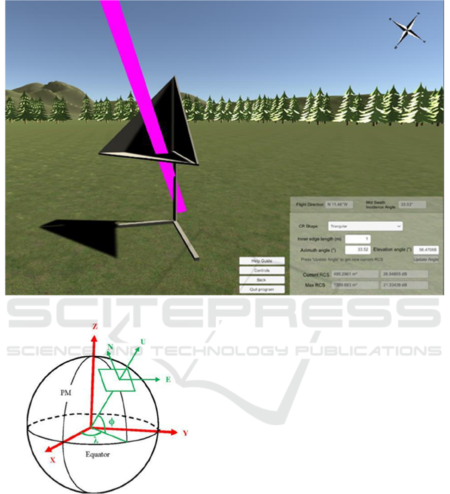
Figure 3: User interface with flight angle and direction with incidence EM waves visualised.
Figure 4: Diagram showing the ECEF and ENU coordinates
system for the Earth, (Wang, Huynh & Williamson, 2013).
In Unity, rotation of objects relies on rotating their
Euler angles which help orientate a rigid body (the
CR) relative to a fixed coordinate system (the Unity
world coordinates).
To change the orientation angles of the CR, both
azimuth and elevation angles have a slightly different
approach. For the azimuth angle, it was important to
check the flight direction to make sure whether the
satellite was looking towards the west or east side. To
make sure that the rotation of the CR is correctly
relative to the radar boresight direction, the local
rotation of the model had to include the flight direction
angle. For example, if the satellite orbit was from south
to north, then the rotation would be equal to:
Δθ = 45 + the flight direction angle – the input
azimuth angle
where Δθ is the change in the azimuth angle.
For the elevation, it did not have to consider the
flight direction of the satellite but only the incidence
angle and tilt the CR according to:
Δψ = 90 – incidence angle – the input elevation angle
Where Δψ is the change in the elevation angle.
Outputting the RCS values were also another
important script and, as shown in the background, the
formulae for the RCS for all three shapes were
mentioned.
4 CONCLUSIONS
In this paper it has been shown how to create a
program with a virtual environment to position corner
CSEDU 2021 - 13th International Conference on Computer Supported Education
182

reflectors and how users, such as students, can use it
to develop their understanding in the field by
experiencing the process on a computer screen. It can
also for example be used in university lectures to
reinforce the understanding of practical techniques
with the support of visualisation. At the moment the
prototype code is available at the University of
Surrey, and as students also improve their VR and
Unity skills, they have options to improve the source
code by adding new corner reflector designs or new
environments.
In the future the following could be addressed to
further expand the current version of the program:
Expand the support for more satellite datasets to
allow for a larger spectrum of data;
Improve the virtual surface environment with
actual local slope and surrounding habitats to increase
accuracy of the results by matching reality;
Provide a wider range of corner reflector options
thus including different materials and reflector types;
Validate RCS results with ground data to check
for the margin of error and improve the proposed
solution;
Move to/implement an immersive virtual reality
version of the current program and allow for a better
first-hand experience.
The development and validation of the present
code is continuing at the University and a fully
working solution is in progress.
REFERENCES
Freeman, A. (1992). SAR calibration: an overview. IEEE
Transactions On Geoscience And Remote Sensing,
30(6), 1107-1121. doi: 10.1109/36.193786
Hu Au, E., & Lee, J. (2017). Virtual reality in education: a
tool for learning in the experience age. International
Journal Of Innovation In Education, 4(4), 215. doi:
10.1504/ijiie.2017.10012691
mgear (2016). Latitude Longitude Position On 3D Sphere
(V2). [Blog Post]. Retrieved 18 February 2021, from
http://unitycoder.com/blog/2016/03/01/latitude-
longitude-position-on-3d-sphere-v2
Matthews, K. (2020). 7 Types Of Virtual Reality That Are
Changing The Future. [Blog Post]. Retrieved 18
February 2021, from
https://www.smartdatacollective.com/7-types-of-
virtual-reality-that- are-changing-future
Molthan, A., Bell, J., & Schultz, L. (2017). Advantages and
Applications of Synthetic Aperture Radar as a Decision
Support Tool. [PowerPoint Slide]. Retrieved from
https://ntrs.nasa.gov/api/citations/20170011226/downl
oads/20170011226.pdf?attachment=true
Pantelidis, V. (2009). Reasons to Use Virtual Reality in
Education and Training Courses and a Model to
Determine When to Use Virtual Reality. Themes in
Science and Technology Education, 2(1-2), 59-70.
Retrieved from http://earthlab.uoi.gr/ojs/theste/index.
php/theste/article/view/22/17.
Subirana, J., Zornoza, J., & Hernández-Pajares, M. (2011).
Transformations between ECEF and ENU coordinates
- Navipedia. Retrieved 28 November 2020, from
https://gssc.esa.int/navipedia/index.php/Transformatio
ns_between_ECEF_and_ENU_coordinates
Sultan, C. (2020). 5 Types Of Virtual Reality – Creating A
Better Future. [Blog Post]. Retrieved 28 November
2020, from https://rextheme.com/types-of-virtual-
reality
Wang, Y., Huynh, G., & Williamson, C. (2013). Integration
of Google Maps/Earth with microscale meteorology
models and data visualization. Computers &
Geosciences, 61, 23-31. doi:
10.1016/j.cageo.2013.07.016
A Virtual Environment Software to Position Corner Reflectors for Assisting in SAR Sensor Calibration
183
