
A Regeneration Placement, Routing and Spectrum Assignment Solution
for Translucent Elastic Optical Networks: A Joint Optimization
Approach
Claudio Gonz
´
alez
1 a
, Nicol
´
as Jara
2 b
and V
´
ıctor M. Albornoz
1 c
1
Department of Industries, Universidad Tecnica Federico Santa Maria, Campus Santiago Vitacura, Chile
2
Department of Electronics Engineering, Universidad Tecnica Federico Santa Maria, Valpara
´
ıso, Chile
Keywords:
Regeneration Placement, Routing, Spectrum Assignment, Elastic Optical Networks, Binary
Integer Programming.
Abstract:
In this paper, we propose a novel joint approach to solve the regeneration placement, routing, modulation
level, and spectrum assignment (RP-RMLSA) problem using a binary integer program (BIP) model. Using
a mock and real-world network topology, we conduct extensive numerical experiments testing the proposed
optimization model’s performance and analyzing the characteristics of the solutions found. Our results show
that considering only an optimal solution occurs when signals in need of regeneration are concentrated in one
regeneration node when considering the regeneration devices’ capital and operational expenditure.
1 INTRODUCTION
Worldwide internet traffic continues to grow due
to the ever-increasing popularity of established and
emerging network services and applications. For
instance, the main content and service providers
(Google, Facebook, Amazon, and Microsoft) have
become the primary source of bandwidth demands
(TeleGeography, 2020). Nowadays, such bandwidth
demands can only be supported by the current in-
stalled optical network infrastructure. However, the
capacity of these networks is expected to be insuffi-
cient. This situation, called “Capacity Crunch” (CC),
manifests an impending inability of current optical ar-
chitectures to support future bandwidth demands (El-
lis et al., 2016; Waldman, 2018).
Two different courses of action can be foreseen to
solve this CC problem. The first option consists of
installing more network resources. This investment
cannot be avoided but should be postponed as long as
possible due to the significant expenses involved. The
second strategy is to manage the already installed net-
work infrastructure efficiently. This second alterna-
tive has been an important focus of research. Current
optical WDM (wavelength division multiplexing) net-
a
https://orcid.org/0000-0001-9661-8822
b
https://orcid.org/0000-0003-2495-8929
c
https://orcid.org/0000-0002-8500-1250
works are inefficient due to the spectrum grid’s coarse
granularity, typically of 50 GHz by channel, accord-
ing to the International Telecommunications Union
(ITU) standard (ITU-T, 2012). This situation implies
that regardless of the user’s bandwidth needs, the en-
tire channel will be reserved.
A new proposal, called Elastic Optical Networks
(EON), has been researched to face previous prob-
lems (Velasco et al., 2017). EON aims to allocate
resources according to the user’s bandwidth require-
ments, dividing the frequency spectrum into narrow
bands called Frequency Slot Unit (FSU), typically of
12.5 GHz. This way, different FSUs can be group
flexibly to satisfy users’ needs. As a consequence, ef-
ficient management of the spectrum is achieved (Ve-
lasco et al., 2017).
One of the main tasks that elastic optical network
operators must resolve is to compute a path and a por-
tion of the frequency spectrum to each network con-
nection, known as the “routing and spectrum assign-
ment” (RSA) problem. This problem becomes more
intricated in continental, and more extensive networks
since a maximum range (in kilometers) can be found
for each connection request due to the accumulation
of physical–layer impairments (PLI). Therefore, we
must add the modulation format on the tasks, called
the “routing, modulation level, and spectrum assign-
ment” (RMLSA) problem. This problem is subject to
González, C., Jara, N. and Albornoz, V.
A Regeneration Placement, Routing and Spectrum Assignment Solution for Translucent Elastic Optical Networks: A Joint Optimization Approach.
DOI: 10.5220/0010393604670474
In Proceedings of the 10th International Conference on Operations Research and Enterprise Systems (ICORES 2021), pages 467-474
ISBN: 978-989-758-485-5
Copyright
c
2021 by SCITEPRESS – Science and Technology Publications, Lda. All rights reserved
467

the following constraints. First, each channel (FSU)
can host by one user at the same time; second, the
same FSU allocated to the said user must be available
in all the links on the user path (continuity constraint);
and in case that the user requires more than one FSU,
the spectrum assigned must be consecutive (contigu-
ity constraint).
The accumulation of PLI limits the generation of
end-to-end all-optical connections (transparent con-
nections) in wide-area optical networks. In fact,
several users may not achieve transparent commu-
nication through long distances despite the modula-
tion format chosen. Therefore, the use of 3R (Re-
amplification, Reshaping, and Retiming) regeneration
in wide-area optical networks cannot be avoided. A
node with regeneration allows increasing connections
optical range, improving the network spectrum usage
by choosing more efficient modulation formats, and
allowing to break the continuity constraint due to the
OEO process. However, these devices add additional
delays for the demands due to the optical transpon-
der (OEO) needed to regenerate and significant de-
ployment and operational costs. Therefore, the use of
these devices should be avoided as much as possible.
RMLSA standard approaches establish transpar-
ent communication between source-destination node
pairs (Velasco et al., 2017; Calder
´
on et al., 2020).
However, due to the need of regenerating on wide–
area networks, some approaches consider the use
of regeneration devices, resulting on translucent (re-
generators found on some nodes) or opaque net-
works (all network nodes have regeneration capa-
bilities) (Chaves et al., 2012; Chaves et al., 2015;
Brasileiro et al., 2019).
The use of regenerator devices must be as effi-
cient as possible, locating them strategically in or-
der to avoid additional costs related to these devices.
This problem is known as “regeneration placement”
(RP) problem. In literature, we can find several op-
timization approaches (Wang et al., 2015; Yıldız and
Karas¸an, 2017). However, optimization approaches
lack a joint solution for the RP and RMLSA prob-
lems or cannot be implemented in real-sized network
topologies. To take advantage of the opportunities of-
fered by the EON requires the jointly solution of RP
and RMLSA problems.
In this work, we propose an integrated optimiza-
tion model for solving the regeneration placement,
routing, modulation format, and spectrum assignment
(RP–RMLSA) problems for translucent elastic optical
networks. We rely on a physical impairment model to
compute the maximum reach of a given modulation
format and bit-rate of a connection request. This strat-
egy focuses on minimizing the use of regenerators due
to the capital and operational expenditure needed, as
well as analyzing the characteristics of good solutions
found through optimality.
The remainder of this article is organized as fol-
lows: Section 2 reviews the main strategies found in
the literature considering regeneration devices. Sec-
tion 3 presents the network assumptions and the opti-
mization model proposal. Section 4 shows some nu-
merical experiments for two network topologies. Fi-
nally, section 5 illustrates conclusions and final re-
marks of the work.
2 STATE OF THE ART
In this section, we conduct a review of the leading
strategies and contributions considering regeneration
found in the literature.
The joint solution for the regenerator place-
ment, routing, modulation level, and spectrum assign-
ment problems (RP–RMLSA) is known to be NP–
hard (Brasileiro et al., 2019; Calder
´
on et al., 2020).
Even some of these problems by themselves are also
known to be NP–hard (Velasco et al., 2017).
Therefore, several ways to solve the regeneration
problem can be found in the literature but with some
sort of simplification. In (Klinkowski, 2012), the au-
thors propose a heuristic algorithm to solve the regen-
eration placement and spectrum assignment problem
jointly, but considering a static demand structure and
a pre–computed fixed path for each network demand.
Relaxing the fix route constraint, in (Kahya, 2013) the
authors present a sequential solution approach, solv-
ing the regeneration placement, routing, spectrum as-
signment problem in EON, but for only one modula-
tion format.
In (Wang et al., 2015) the authors present a
Mixed–Integer Linear Programming (MILP) formu-
lation to solve the regeneration placement problem in
an elastic optical network. Since their proposal can
not solve real-size problems, they proposed a sequen-
tial heuristic approach randomly partitioning the set
of demands.
In (Yıldız and Karas¸an, 2017) the authors present
a branch–and–price algorithm to jointly solve the RP–
RMLSA problem for real–size network topologies.
They introduce a path segment formulation of the
route to simplify the problem, imposing the maximum
optical reach for the network demands. In our study,
we use the same strategy but differing on the spectrum
assignment treatment. Yildiz et al. compute only the
usage of FSUs on each link by not calculating the por-
tion of the spectrum used by all the network users; this
way simplifying the model. However, network opera-
ICORES 2021 - 10th International Conference on Operations Research and Enterprise Systems
468

tors demand the position of the FSUs assigned to each
network user in order to configure the network and as-
sess the quality of the solution.
On the other hand, the regeneration problem in
EON has been solved considering two different prob-
lems in a hierarchical modeling approach: the Re-
generator Placement (RP) and Regenerator Assign-
ment (RA) problems (Fontinele et al., 2016). The
RP problem defines which nodes will allow regener-
ation capacity, and the RA problem defines, in each
node, which connections are regenerated. Hence, the
RP problem must be solved during the network plan-
ning phase while the RA problem during the network
operation phase. The algorithms used to solve the
RP problem are: Maximum Simultaneously Used Re-
generator Placement (MSU), Most Used Regenera-
tor Placement (MU), Distance Adaptive Regenerator
Localization Algorithm (DA), and Node Degree First
(NDF) (Chaves et al., 2012). The algorithms used to
solve the RA problem are: First Longest Reach Re-
generator Assignment (FLR), First Narrowest Spec-
trum Regenerator Assignment (FNS) (Chaves et al.,
2015) and Circuit Invigorating Regenerator Assign-
ment (CIRA) (Brasileiro et al., 2019).
To the best of our knowledge, our study is the
first to consider every aspect of EON for the regen-
eration placement problem. To solve the regeneration
placement, routing, modulation format, and spectrum
assignation problem, we use the same path–segment
formulation found in (Yıldız and Karas¸an, 2017) but
including the spectrum utilization decision and con-
straints.
3 NETWORK ASSUMPTIONS
AND MODEL
This section comprises the main contribution of the
article. First, we describe the physical–layer impair-
ment model used to determine the number of FSU’s
assigned to each demand. Then, we present the opti-
mization model used to jointly solve the regeneration
placement problem (RP) and the RMLSA problem.
3.1 Physical-layer Impairments Model
The quality of transmission (QoT) of optical signals
is degraded by different phenomena occurring during
the modulation, propagation, and detection processes.
In particular, to solve the RMLSA problem, we con-
sider the impact that the amplified spontaneous emis-
sion (ASE) noise and non–linear interference noise
has on the QoT. The accumulation of noise during
propagation determines the maximum optical reach
that a signal can have for a given modulation level
and bit error rate (BER) combination. With a high
number of bits per symbol, complex modulation for-
mats increase the transmission sensitivity to degra-
dation. Thus, the transmission reach is shorter for
higher modulation levels compared to simpler for-
mats (Yaghubi-Namaad et al., 2018). To consider this
route length - modulation level trade–off, the most
common approach is to associate any modulation for-
mat available at the transponder to its maximum trans-
mission reach for a given BER value (Talebi et al.,
2014). This approach is also used in this work.
The modulation formats used in this work are bi-
nary phase-shift keying (BPSK), quadrature phase-
shift keying (QPSK), and Λ–quadrature amplitude
modulation (Λ-QAM), where Λ takes values 8 and 16.
Table 1 shows the transmission reach, using single-
polarization, as a function of the modulation format
and bit–rates available at the transponders. The first
two columns in Table 1 show the maximum achiev-
able reach (MAR) that an optical signal can travel
without exceeding a BER of 10
−6
. – assuming single-
polarization – as a function of the modulation format
available at the transponders. The optical reach values
were obtained using the GN model (Poggiolini et al.,
2014) to estimate the received signal–to–noise ratio
(SNR) degraded by ASE noise and non–linear inter-
ference noise. For more details about the optical reach
calculation, the reader is referred to (Calder
´
on et al.,
2020), Section III.
Table 1: Maximum achievable reach (MAR) per modula-
tion format and FSU requirements per bit–rate and modula-
tion format pair, for a BER value equal to 10
−6
.
Modulation MAR [km]
Bit-rates
10 40 100
BPSK 5525 1 4 8
QPSK 2720 1 2 4
8-QAM 1360 1 2 3
16-QAM 560 1 1 2
3.2 Optimization Model
This subsection presents a binary integer program
(BIP) to solve the regenerator placement, routing,
modulation format, and spectrum assignment prob-
lem (RP–RMLSA), as well as its notation.
Let G(N, A) be a directed graph representing an
elastic optical network with node set N, and optical
arc set A. The arc length are denoted by l
i, j
for each
arc (i, j) ∈ A. We denote the set M as the available
modulation formats, where l
m
represents the maxi-
mum achievable reach of modulation m ∈ M. We de-
fine D as the set of transmission demands. For each
A Regeneration Placement, Routing and Spectrum Assignment Solution for Translucent Elastic Optical Networks: A Joint Optimization
Approach
469

demand d ∈ D we denote o
d
as the source node, t
d
as
the destination node, and b
d
as the requested bit–rate
in Gbps.
For the route assignment part of the problem
we use the path segments formulation (Yıldız and
Karas¸an, 2017). A path segment p is a directed sim-
ple path with an associated modulation level m(p). A
directed path is simple if it does not repeat any node.
We denote the source and destination nodes of a path
segment p as o
p
and t
p
, respectively. Let in
i, j, p
be
a parameter equal to 1 if the arc (i, j) ∈ A is part of
the path segment p. This way, we can calculate the
length of the path–segment l
p
=
∑
(i, j)∈A
l
i, j
· in
i, j, p
as
the sum of the arcs contained within p. Considering
that each path–segment p is associated with a mod-
ulation format m(p), a path–segment is feasible if it
respects the MAR limitation of its own modulation
format(Table 1). Namely, a path–segment p is feasi-
ble if l
p
≤ l
m(p)
. We define P as the set of all feasi-
ble path–segments. Then, a route is an ordered union
of feasible path–segments p
i
∈ P, i ∈ 1, ··· , k where
t
p
i
= o
p
i+1
for all i = 1, · · · , k − 1. For that route to
be assigned to demand d it must satisfy that o
p
i
= o
d
and t
p
k
= t
d
. With this path–segment formulation, the
MAR restriction is implicitly taken into consideration
by using only the feasible path–segments.
We denote S as the set of FSU available for all
optical fibers. The amount of FSU required for a de-
mand d depends on the modulation level used and the
amount of bit–rate requested. So, we denote the set of
connections C(m, b
r
) = {1, 2, · · · ,c} as all the differ-
ent positions inside the spectrum where it can be as-
signed the signal depending on the bit–rate and mod-
ulation format. It does not depends on the fiber used.
As an example, for modulation format BPSK and a
bit–rate of 40 Gbps, the amount of FSU required is
4 and C(m = BPSK, b
r
= 40) represent the c different
ways to assigned those 4 consecutive FSU in the spec-
trum represented by S. Let p
c,s
be a parameter equal
to 1 if the connection c ∈ C uses the FSU s ∈ S within
the spectrum. Then, forall c ∈ C(m, b
r
) the contiguity
constraint is implicitly imposed by the proper defini-
tion of p
c,s
such that ∀i, j ∈ S : p
c,i
= p
c, j
= 1, i < j ⇒
p
c,k
= 1, ∀k ∈ {i, ··· , j}. And
∑
s∈S
p
c,s
is equal to the
amount of FSU needed given in Table 1. We denote C
as the set of all possible positions for any amount of
FSU required. So, C(m, b
r
) is a subset of C.
For the regeneration aspect, we denote c
o
as the
capital cost of installing a regenerator in node i ∈ N,
and η as the cost of operating that regenerator for
each signal regenerated. Using the path–segment for-
mulation, where the route is the ordered union of
p
i
, i ∈ 1, ··· , k, we can identify t
p
i
as a regeneration
node for all i = 1, ··· , k − 1. In other words, to use
Table 2: Outline of notation.
N Set of nodes, index n.
A Set of arcs.
M Set of modulation formats, index m.
D Set of demands, index d.
P Set of feasible path–segments, index
p.
S Set of FSU, index s.
C Set of all connections available.
C(m, b
r
) Subset of connections available for
modulation m and bitrate b
r
.
o
d
Source node of demand d.
t
d
Destination node of demand d.
b
d
Bitrate requested by demand d.
o
p
Source node of path–segment p.
t
p
Destination node of path–segment p.
m(p) Modulation format associated with
the path–segment p.
in
i, j, p
Equal to 1 if arc (i, j) ∈ A is part of
the path–segment p.
p
c,s
Equal to 1 if connection c uses slice
s ∈ S.
c
o
Cost for regenerator placement.
η Regenerator usage cost.
more than one path–segment the signal must be regen-
erated. Another aspect to consider is that there must
be only one connection used for each path–segment
used by demand d.
Since it is of interest to use the least amount of re-
generators, the main objective is to minimize the to-
tal capital and operational cost of regeneration. So
the RP–RMLSA problem can be formally stated as
follow: given a graph G(N, A), the total spectrum
S, the modulation formats M and the traffic demand
D, we obtain as output the route composed by path–
segments and the connection for each demand and the
nodes where the demands regenerated, resulting from
the minimization of the total cost of regeneration. The
notation we use throughout this paper is outlined in
Table 2.
The decision variables of the model are:
x
d pc
a binary decision that takes a value
equal to 1 if demand d use path–
segment p with connection c and 0
otherwise.
r
n
a binary decision that takes a value
equal to 1 if node n is a regeneration
point and 0 otherwise.
We name x
d pc
as the flow variable that represents
the routing and spectrum assignment decision. As
we mentioned, the route is a concatenation of path–
ICORES 2021 - 10th International Conference on Operations Research and Enterprise Systems
470

segments, and in every path–segment where the de-
mand passes through, we need to assign only one
position inside the spectrum. So if
∑
p∈P
x
d pc
≥ 1 it
means that it regenerated because it use more than one
path–segment. We name r
n
, n ∈ N as the regeneration
variable and indicates if node n is a regeneration site
or not.
Then, the RP-RMLSA formulation is as follows:
min
∑
n∈N
c
o
r
n
+
∑
d∈D
p∈P
c∈C
t
p
6=t
d
ηx
d,p,c
(1)
subject to:
∑
p∈P
o
p
=i
∑
c∈C(d)
x
d pc
−
∑
p∈P
t
p
=i
∑
c∈C(d)
x
d pc
=
1 if i = o
d
−1 if i = t
d
0 e.o.c
∀i ∈ N, d ∈ D
(2)
∑
c∈C
x
d pc
≤ 1 ∀d ∈ D, p ∈ P (3)
∑
p∈P
t
p
=n
x
d pc
≤ r
n
∀d ∈ D, c ∈ C, n ∈ N \ t
d
(4)
∑
p∈P
∑
d∈D
∑
c∈C(m(p),b
d
)
in
i, j, p
· p
c,s
· x
d pc
≤ 1
∀(i, j) ∈ A, s ∈ S
(5)
x
d pc
∈ {0, 1}, ∀d ∈ D, p ∈ P, c ∈ C (6)
r
n
∈ {0, 1}, ∀n ∈ N (7)
The objective function (1) minimize both the total
cost of installing a regeneration site on the nodes and
the cost of regenerating a signal. The first term rep-
resents the fixed cost of setting a regenerator site in
node n. The second term represents the cost of adding
a regenerator device to the regenerator site.
Constraints (2) are the flow balance equations that
force each demand to be carried from its source to
its destination. Constraints (3) are the continuity con-
straint which ensures that only one connection is used
for every path–segment and demand. Constraints (4)
enforce regeneration requirements by ensuring regen-
eration at the end of each possible path–segment that
does not end in the destination node of the associated
demand. Constraints (5) guarantees that every FSU at
every arc is assigned at most to one demand. Finally,
constraints (6) and (7) define the binary nature of the
variables. This formulation is quite compact but con-
tains every aspect of the regeneration and the RMLSA
problems.
With this model’s output, we can compute the
number of signals regenerated in the regeneration site
and see the spectrum utilization. The first one states
as follows:
nr
n
=
∑
d∈D
p∈P
c∈C
t
p
=n
t
p
6=t
d
x
d,p,c
∀n ∈ N (8)
where nr
n
is the number of signals regenerated in
node n. The second one can be compute as follows:
u
i, j,s
=
∑
p∈P
∑
d∈D
∑
c∈C(m(p),b
d
)
in
i, j, p
· p
c,s
· x
d pc
∀(i, j) ∈ A, s ∈ S.
(9)
where u
i, j,s
is equal to 1 if FSU s is used by a demand
in arc (i, j). With these extra results we expand the
amount of info the RP-RMLSA gives without making
more complex the formulation.
4 NUMERICAL EXPERIMENTS
In this section, several numerical experiments are
conducted to test the proposed solution and derive
insights from the instances. We implemented the
optimization model using AMPL under MacOS and
GUROBI 9.0.2. All experiments were done on a 3.1
GHz Dual–Core Intel Core i5 with 8 GB of RAM.
Table 3: Network characteristics summary.
Parameter Value
Topology Basic Net, NSFNet
Links Capacity 40 slots
Bitrates 10, 40, 100 Gbps
Modulation
formats
BPSK, QPSK, 8-QAM, 16-QAM
FSUs and MAR Table 1
Table 3 summarizes the network characteristics in
which we execute our proposal. First, we studied a
mock network called Basic Net (Figure 1) in order
to preliminary test the model. Then, we use the well-
known real network topology NSFNet (Figure 2). Ex-
tra network information can be found in Table 4.
Table 4: Network topologies parameters.
Network Nodes Links Demands
Basic Net 7 11 42
NSFNet 14 21 182
A Regeneration Placement, Routing and Spectrum Assignment Solution for Translucent Elastic Optical Networks: A Joint Optimization
Approach
471

0
1
2
3
4
5
6
Figure 1: Basic Net network.
0
1
2
3
4
5
6
7
8
10
9
11
12
13
Figure 2: NSFNet network.
We compute the feasible set S composed of path–
segments based on each network arc length and the
available modulation formats available for each exer-
cise. The network capacity was set to 1/8 of the to-
tal C-band spectrum frequency (40 FSUs per network
link) (Calder
´
on et al., 2020).
We assume that every source–destination node
pair demand communication (|D| = |N| · (|N| − 1).
The bit–rate requests were defined for each connec-
tion request using two criteria: the first one assigns
randomly the bit–rate to each user uniformly dis-
tributed between the values 10, 40, and 100 Gbps; and
the second one assigns the worst–case scenario with
only the highest bit–rate available, this is 100 Gbps
for all connection requests. The second scenario is
considered the worst one since demands would need
the highest amount of FSU possible, increasing link
usage, and even increasing demand regeneration to
reach destination nodes.
For this study, we run five instances of the pro-
posed model considering different scenarios. Table 5
shows the solutions of the RP-RMLSA model for
these instances. The first four columns represent the
different characteristics of the instances. The Basic
Net was only executed for the two criteria of bit–rate
assignment, both using BPSK to 8QAM as an option
for their connection modulation formats. On the other
hand, the NSFNet was solved for both bit–rate as-
signment criteria and two different ranges of modu-
lation formats (MF). These are BPSK to 8QAM and
QPSK to 16QAM. The differences in modulation for-
mats availability are based on increasing the chances
of regeneration on the execution since complex mod-
ulation formats have a higher spectrum efficiency but
with a lesser optical reach, incurring a higher use of
regeneration.
The PS column represents the number of path–
segments pre–computed. Lastly, the remaining
columns represent the solution obtained by executing
our model. For instance, the Basic Net with random
bit–rate (Instance 1), the solution takes 17.8 seconds
(RunTime column), it only used the node 3 (RN col-
umn) to regenerate two connection requests (NR), and
with a spectrum frequency usage of 31.4% (%FSU
column).
As shown in Table 5, almost on all the instances,
the RP-RMLSA model chooses one at most one re-
generation node as a regeneration site, then concen-
trating the regeneration of several connections in only
one network node despite the number of connections
being regenerated along their paths. This situation
makes sense because the objective function is to mini-
mize the costs related to regenerate optical signals. As
expected, the running time of the instances with Basic
Net was shorter than the ones with NSFNet because of
the number of nodes, links, and demands. In fact, the
computational complexity of the RP-RMLSA prob-
lem makes more difficult to solve large instances of
the problem, as we can see at Instance 5.
In the Basic Net it regenerated on node 3 for both
instances. In this case, the regeneration site is on the
network core, also the node serving a larger number
of users. We can see that the result of both random
and worst–case instances is the same; the difference
is in the running time and the spectrum’s utilization.
In the regeneration model, the primary constraint is
the MAR, so increasing traffic in this network did not
affect the regeneration decision.
On the NSFNet network, Instance 3 did not need
to regenerate. This situation is due to the short dis-
tances of the arcs, where the minimum, average and
maximum lengths are 212, 509, and 1140 km, respec-
tively. By removing BPSK and adding 16QAM as
a modulation format option, we are forcing the net-
work to regenerate. So as expected, Instance 4 regen-
erate six demands in node 0. This node is on the net-
work fringe, in contrast to the Basic Net solution. Ta-
ble 6 exemplifies the six connection demands regen-
erated on the fifth instance separated by their path–
segments. Notice that the users with regeneration are
three nodes pairs communicating in a round–trip, For
ICORES 2021 - 10th International Conference on Operations Research and Enterprise Systems
472
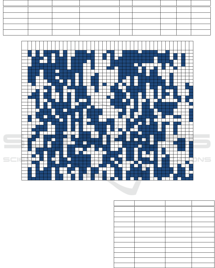
Table 5: Results of the RP-RMLSA model.
Instances Network Bitrate MF PS RunTime RN N
o
R %FSU
1 Basic Net Random BPSK to 8QAM 122 17.885 3 2 31.4
2 Basic Net Worst Case BPSK to 8QAM 122 50.845 3 2 50.3
3 NSFNet Random BPSK to 8QAM 682 4472.390 None 0 60.5
4 NSFNet Random QPSK to 16QAM 404 46375.800 0 6 55.0
5 NSFNet Worst Case QPSK to 16QAM 404 298426.400 0 6 68.3
FSU
(0, 1)
(0, 2)
(0, 7)
(1, 2)
(1, 3)
(2, 5)
(3, 4)
(3, 10 )
(4, 5)
(4, 6)
(5, 9)
(5, 13 )
(6, 7)
(7, 8)
(8, 9)
(8, 11 )
(8, 12 )
(10, 11 )
(10, 12 )
(11, 13 )
(12, 13 )
(1, 0)
(2, 0)
(7, 0)
(2, 1)
(3, 1)
(5, 2)
(4, 3)
(10, 3)
(5, 4)
(6, 4)
(9, 5)
(13, 5)
(7, 6)
(8, 7)
(9, 8)
(11, 8)
(12, 8)
(11, 10 )
(12, 10 )
(13, 11 )
(13, 12 )
1 1 0 1 0 1 1 1 1 0 1 0 0 1 1 1 0 1 0 0 0 1 1 0 0 1 1 1 1 0 1 1 1 1 0 0 1 0 0 0 0 0 0
2 1 0 1 0 1 1 0 1 0 1 0 0 1 1 1 1 1 0 0 1 0 1 0 0 1 1 1 1 1 1 1 1 1 1 1 1 0 1 0 1 0 0
3 0 1 1 1 0 1 0 1 1 1 0 1 1 1 1 1 1 0 0 1 0 1 0 1 1 1 1 1 1 1 1 1 0 1 1 1 0 1 0 1 0 0
4 0 1 1 0 0 1 0 1 1 1 0 1 1 1 1 0 1 0 0 0 0 1 1 1 1 1 1 1 1 1 1 1 0 1 1 1 1 0 0 1 0 0
5 0 1 1 1 1 1 1 1 1 1 0 1 1 1 0 0 1 0 0 0 0 1 1 1 1 1 1 0 1 0 0 0 0 0 1 0 1 0 0 1 0 0
6 1 1 1 1 1 1 1 1 1 1 0 1 1 1 0 0 1 0 0 0 1 1 0 1 1 1 1 1 0 1 0 0 1 0 1 0 0 1 0 0 0 0
7 1 1 1 0 1 1 1 0 1 1 1 1 1 1 0 0 0 0 0 0 0 0 0 1 1 1 1 1 0 1 0 1 1 0 0 0 0 0 0 0 0 0
8 1 1 1 0 1 1 1 1 1 1 1 1 0 1 0 0 0 1 0 0 0 0 0 1 1 1 1 1 1 1 0 1 1 0 0 0 1 0 0 0 0 0
9 1 1 0 0 1 1 1 0 1 1 1 1 0 1 0 0 1 1 0 0 0 0 0 1 1 0 1 0 1 1 1 1 1 1 0 0 1 0 0 0 0 0
10 1 1 0 0 0 1 1 1 0 1 0 1 0 1 0 0 1 1 0 0 0 0 0 1 0 0 1 0 1 1 1 1 1 1 1 0 1 0 0 0 0 0
11 0 1 0 0 0 0 1 1 1 1 0 1 0 1 0 0 1 1 0 1 0 0 1 0 1 0 1 0 1 1 0 1 1 1 1 0 1 0 0 0 1 0
12 0 0 0 0 1 1 0 1 1 0 1 1 1 1 1 0 0 1 0 0 0 1 1 0 0 1 1 1 1 1 0 1 1 0 1 1 1 1 0 0 1 1
13 0 0 1 0 0 1 0 1 1 0 0 0 1 1 1 0 0 1 0 0 0 1 1 1 0 1 1 1 1 1 0 0 1 0 1 0 0 1 0 0 0 1
14 0 1 1 0 1 1 0 0 1 0 1 0 1 1 1 0 0 0 0 0 0 0 1 1 1 0 1 1 0 1 0 0 1 0 1 1 0 1 0 0 0 1
15 1 1 1 0 1 1 0 0 1 0 1 0 1 1 1 1 0 0 0 0 1 0 1 1 1 0 1 1 0 1 0 0 1 0 1 0 0 1 1 0 1 1
16 0 0 1 0 0 1 1 0 1 0 1 0 1 0 0 1 0 0 0 0 0 1 1 1 0 1 0 1 0 0 1 0 0 1 0 0 0 0 1 0 1 0
17 0 0 1 0 1 0 1 1 1 1 1 0 0 1 1 1 0 0 0 0 0 1 1 1 1 1 0 1 0 1 1 0 1 1 1 1 1 1 0 0 0 1
18 0 0 1 0 1 0 1 1 1 1 1 0 1 1 1 0 1 0 0 0 0 0 1 1 1 0 0 1 0 1 1 0 1 1 1 1 1 1 0 0 0 0
19 0 0 0 1 1 1 0 1 1 0 1 1 1 1 0 1 1 1 1 0 0 0 0 0 1 0 1 1 0 1 1 1 0 1 1 1 1 0 0 0 0 1
20 0 0 1 1 1 1 0 1 1 1 1 1 0 1 0 1 1 1 1 0 0 0 0 1 1 0 1 0 0 1 1 1 0 0 1 1 1 0 0 0 0 1
21 1 0 1 1 0 1 1 0 1 1 0 1 0 1 0 1 1 1 0 0 0 0 0 1 0 0 1 0 1 1 1 1 1 0 1 0 0 1 1 0 0 1
22 1 0 0 1 1 1 1 1 0 1 0 1 1 1 0 0 1 1 0 0 1 1 0 0 0 1 0 1 1 1 0 1 0 0 0 0 0 0 0 0 0 1
23 0 0 0 0 1 0 1 1 1 1 0 1 0 1 0 1 1 1 1 1 1 1 0 0 0 1 1 1 0 1 0 1 1 0 1 1 0 1 1 0 0 0
24 0 0 1 1 1 0 0 1 1 1 0 1 0 1 0 0 0 1 1 1 0 1 0 0 0 1 1 0 1 1 1 1 1 0 1 0 0 1 0 0 0 0
25 0 1 1 1 1 0 0 1 1 1 0 1 0 1 0 0 0 1 1 1 0 1 0 1 0 1 0 0 1 1 1 1 1 0 1 0 0 1 0 0 0 0
26 0 0 1 0 0 0 0 1 1 0 0 0 0 1 1 1 0 0 1 1 0 0 0 0 1 0 1 1 0 1 1 1 1 1 1 0 0 1 0 0 0 0
27 0 1 1 0 1 1 1 1 1 1 0 1 0 1 1 1 0 0 1 0 1 0 0 1 1 0 1 1 1 1 1 0 1 1 1 0 0 0 0 0 0 0
28 1 1 0 0 1 1 0 1 1 0 0 1 1 1 1 1 1 1 1 0 1 0 1 1 1 0 1 0 1 0 1 0 1 1 1 0 0 0 1 1 0 0
29 1 0 0 0 1 0 1 1 1 0 0 0 1 1 0 1 1 1 1 0 1 0 0 0 1 1 1 1 1 1 1 0 1 0 0 0 0 1 1 1 0 1
30 1 0 0 0 1 0 1 1 1 0 1 1 1 1 1 1 0 1 1 1 1 0 0 0 1 1 1 1 0 1 1 1 1 0 0 0 0 0 1 1 0 1
31 1 0 1 1 1 1 1 1 1 0 1 1 0 0 1 0 0 1 0 1 1 0 0 1 0 1 1 0 1 1 1 1 1 0 1 0 0 0 1 1 0 1
32 0 0 1 1 0 1 1 0 1 0 1 1 0 1 0 0 0 0 0 0 1 1 1 1 0 1 1 0 1 0 1 0 1 0 1 0 0 0 0 0 0 1
33 0 1 0 1 0 1 1 0 1 0 1 1 1 1 1 1 0 0 0 1 1 1 1 0 0 1 1 0 1 0 0 0 1 0 0 1 0 0 0 0 0 1
34 0 0 0 1 0 1 0 0 1 1 0 1 1 1 1 1 0 0 0 1 1 0 1 1 0 1 1 0 1 1 1 0 1 0 1 1 0 0 0 0 0 0
35 0 1 1 0 0 1 1 0 1 1 1 1 1 1 1 1 0 0 0 1 1 1 0 1 0 0 0 1 0 1 1 1 1 0 1 1 0 0 0 0 1 0
36 0 0 1 0 0 1 1 1 1 1 0 1 1 1 1 1 0 0 1 1 0 1 1 0 0 0 1 0 1 0 0 0 1 0 1 1 0 0 1 0 0 1
37 1 0 1 0 1 1 0 1 0 0 1 1 0 1 1 0 1 1 0 0 0 0 1 1 0 0 1 1 1 0 1 0 1 1 1 1 1 0 1 1 0 1
38 1 0 1 1 1 1 0 1 0 0 1 0 0 1 1 0 1 1 0 1 0 0 1 1 0 1 1 1 1 1 1 0 1 1 1 1 1 0 1 1 0 0
39 1 0 1 1 1 1 0 1 1 0 0 1 0 1 0 0 1 0 0 1 0 0 1 1 0 1 1 1 1 1 1 0 1 1 1 1 0 1 1 1 0 1
40 1 1 1 1 1 1 0 1 1 0 0 1 0 1 0 0 1 0 0 1 0 1 0 1 0 1 0 1 0 1 1 0 0 1 0 0 0 1 0 1 1 1
Figure 3: Spectrum utilization for instance 4.
instance, demands transmitting from node 1 to 12 and
vice–versa (see demand 25 and 158 in Table 6). The
same occurred in the Basic Net, with only one origin–
destination pair.
Additionally, we can see that some demands
changed the modulation format used on the differ-
ent segments. This situation can be explained since
users search for a room on each link’s used capacity,
therefore choosing a modulation format with higher
spectrum efficiency if needed. However, It does not
always select the most efficient modulation because it
only minimizes the cost of using regeneration, not the
spectrum usage.
Another interesting analysis is related to the uti-
lization of the spectrum. By including regenera-
tor nodes, we decrease the percentage of spectrum
used. This reduction is coherent with previous ref-
erences (Klinkowski, 2012). However, since we do
Table 6: Demands with regeneration for instance 4.
Demand Path-Segment Modulation FSU used
25 (1,0) QPSK 32,33
25 (0,7,8,12) QPSK 20,21
37 (2,0) QPSK 28
37 (0,7,8,11) QPSK 26
47 (3,1,0) 8QAM 16,17
47 (0,7,8) QPSK 1,2
108 (8,7,0) QPSK 31,32
108 (0,1,3) 8QAM 1,2
146 (11,8,7,0) QPSK 20
146 (0,2) QPSK 33
158 (12,8,7,0) QPSK 21
158 (0,1) 16QAM 14
not minimize the spectrum usage on the model, the
utilization is not optimal. As we can see in Figure 3,
the spectrum assignment does not seem to follow any
observable rule. So the amount of fragmentation in
A Regeneration Placement, Routing and Spectrum Assignment Solution for Translucent Elastic Optical Networks: A Joint Optimization
Approach
473

the spectrum is very high. This performance opens
the possibility of applying a de-fragmentation method
like the ones found in (Velasco et al., 2017) or mod-
ifying the RP-RMLSA formulation to minimize the
network fragmentation.
5 CONCLUSIONS
In this work, we propose a BLP formulation to jointly
solve the regeneration placement, routing, modulation
format, and spectrum assignment problems (known as
RP–RMLSA). The RP–RMLSA model formulated is
both complete and straightforward, considering every
characteristic of the elastic optical network architec-
tures, and regeneration devices. We show through dif-
ferent instances that the optimal number of regenera-
tion sites is one or none, located on different network
nodes depending on the topology. Finally, when re-
generation occurs on a given source–destination node,
it will also regenerate the same node pair but transmit-
ting on the opposite side, solving the problems sym-
metrically.
Future work intends to include a cost of frag-
mentation to the RP–RMLSA formulation, seeking
to minimize both the regeneration cost and the spec-
trum usage on the network links. Also, we intend to
test the model with larger networks trying to reduce
the execution time with OR techniques aiming to face
the computational complexity of the problem. Finally,
formulate an RP algorithm to reach a similar solution
found in the RP–RMLSA model but with consider-
ably lower running time, assessing the trade–off be-
tween complexity and optimality, and compare it with
the hierarchical modeling approach.
ACKNOWLEDGEMENTS
This work received financial support from PI
LII
2020 74, and DGIIP masters scholarship program
from USM, as well as ANID FONDECYT Iniciaci
´
on
11201024.
REFERENCES
Brasileiro,
´
I., Valdemir, J., and Soares, A. (2019). Regen-
erator assignment with circuit invigorating. Optical
Switching and Networking, 34:58–66.
Calder
´
on, F. I., Lozada, A., B
´
orquez-Paredes, D., Olivares,
R., Davalos, E. J., Saavedra, G., Jara, N., and Leiva,
A. (2020). Ber-adaptive rmlsa algorithm for wide-area
flexible optical networks. IEEE Access, 8:128018–
128031.
Chaves, D. A., Carvalho, R. V., Pereira, H. A., Bastos-Filho,
C. J., and Martins-Filho, J. F. (2012). Novel strate-
gies for sparse regenerator placement in translucent
optical networks. Photonic Network Communications,
24(3):237–251.
Chaves, D. A., da Silva, E. F., Bastos-Filho, C. J., Pereira,
H. A., and Almeida, R. C. (2015). Heuristic algo-
rithms for regenerator assignment in dynamic translu-
cent elastic optical networks. In 2015 17th Interna-
tional Conference on Transparent Optical Networks
(ICTON), pages 1–4. IEEE.
Ellis, A. D., Mac Suibhne, N., Saad, D., and Payne, D. N.
(2016). Communication networks beyond the capac-
ity crunch. Philosophical Transactions of the Royal
Society A: Mathematical, Physical and Engineering
Sciences, 374(2062).
Fontinele, A., Santos, I., Dur
˜
aes, G., and Soares, A. (2016).
Achievement of fair and efficient regenerator alloca-
tions in translucent optical networks using the novel
regenerator assignment algorithm. Optical Switching
and Networking, 19:22–39.
ITU-T (2012). Spectral grids for wdm applications: Dwdm
frequency grid. ITU-T G.694.1, Telecommunication
Standardization Sector of ITU, Ginebra, Switzerland.
Kahya, A. (2013). Routing, spectrum allocation and re-
generator placement in flexible-grid optical networks.
PhD thesis, bilkent university.
Klinkowski, M. (2012). On the effect of regenerator place-
ment on spectrum usage in translucent elastic optical
networks. In 2012 14th International Conference on
Transparent Optical Networks (ICTON), pages 1–6.
IEEE.
Poggiolini, P., Bosco, G., Carena, A., Curri, V., Jiang, Y.,
and Forghieri, F. (2014). The gn-model of fiber non-
linear propagation and its applications. Journal of
Lightwave Technology, 32:694–721.
Talebi, S., Alam, F., Katib, I., Khamis, M., Salama, R., and
Rouskas, G. N. (2014). Spectrum management tech-
niques for elastic optical networks: A survey. Optical
Switching and Networking, 13:34–48.
TeleGeography (2020). The state of the network 2020 edi-
tion.
Velasco, L., Vela, A. P., Morales, F., and Ruiz, M. (2017).
Designing, operating, and reoptimizing elastic op-
tical networks. Journal of Lightwave Technology,
35(3):513–526.
Waldman, H. (2018). The Impending Optical Network Ca-
pacity Crunch. Sbfoton Conference, pages 1–3.
Wang, X., Brandt-Pearce, M., and Subramaniam, S. (2015).
Impact of wavelength and modulation conversion
on translucent elastic optical networks using milp.
Journal of Optical Communications and Networking,
7(7):644–655.
Yaghubi-Namaad, M., Rahbar, A. G., and Alizadeh, B.
(2018). Adaptive modulation and flexible resource al-
location in space-division-multiplexed elastic optical
networks. Journal of Optical Communications and
Networking, 10(3):240–251.
Yıldız, B. and Karas¸an, O. E. (2017). Regenerator loca-
tion problem in flexible optical networks. Operations
Research, 65(3):595–620.
ICORES 2021 - 10th International Conference on Operations Research and Enterprise Systems
474
