
Predictive Maintenance Model based on Asset Administration Shell
Salvatore Cavalieri
a
and Marco Giuseppe Salafia
b
University of Catania, Department of Electrical Electronic and Computer Engineering (DIEEI),
Viale A. Doria, 6, 95125 Catania, Italy
Keywords: Industry 4.0, Asset Administration Shell, Rami 4.0, Predictive Maintenance, Interoperability.
Abstract: Maintenance is one of the most important aspects in industrial and production environment. The availability
of huge amount of data coming from sensors and embedded systems, enabled the realisation of Predictive
maintenance (PdM). It is an approach that aim to schedule maintenance tasks on the basis of historical data
before the occurrence of failures, avoiding machine block downs and reducing the costs due to unnecessary
maintenance actions. The adoption of vendor-specific solutions for predictive maintenance and the
heterogeneity of technologies adopted in the brownfield for the condition monitoring of machinery reduce the
flexibility and interoperability required by Industry 4.0. The paper presents a PdM model leveraging on the
Asset Administration Shell (AAS) introduced in Reference Architecture Model for Industrie 4.0 (RAMI 4.0)
as a means to enhance interoperability and enabling flexibility and re-configuration of the production against
a PdM solution.
1 INTRODUCTION
Industry 4.0 introduced the application of modern
Information & Communication Technologies (ICT)
concepts in industrial contexts to create more flexible
products and services leading to new business models
and added value (Liao, 2017; Xu, 2018). This fourth
industrial revolution features flexible and adaptable
manufacturing concept to satisfy a market requiring
an increasing demand of customisation (Panda,
2018).
Among the main ICT solutions introduced in the
Industry 4.0, Industrial Internet of Things (IIoT)
allows the availability of huge amount of data coming
from sensors and embedded systems installed in a
modern plant (Khana, 2019). The Big Data so
available may be used for several purposes in order to
improve the performances of the factory.
Maintenance is of paramount importance since
avoiding failures is a key requirement in a
challenging market asking for high efficiency and
availability. An efficient use of historical data
collected by IIoT systems consists of predictive
maintenance (PdM) where maintenance actions are
scheduled when either a deterioration or a
a
https://orcid.org/0000-0001-9077-3688
b
https://orcid.org/0000-0002-9381-3857
degradation in the performances of the machinery is
detected by a suitable analysis of historical data.
Literature presents several PdM solutions
involving different technologies and approaches,
from the gathering of data to the prognostics of
failures. Furthermore, in the context of the fourth
industrial revolution, lots of different technologies
and protocols are adopted from the brownfield area
(i.e. sensors, fieldbuses) to the IT area. The adoption
of vendor-specific solutions for PdM reduces the
flexibility and interoperability required by Industry
4.0. Therefore, the definition of PdM solutions that
can adapt itself to the variation in the configuration of
the original production is hard to realise, setting new
constraints to the flexibility in the smart factory. What
is required is horizontal integration to hide
implementation details between devices, regardless
of both their manufacturer and technologies adopted.
In this manner, a device can be easily replaced with
an equivalent one providing the same functionalities.
In order to satisfy the requirements of
interoperability and flexibility demanded by industry
4.0, an approach for the definition of a PdM program
must address two main objectives: 1) defining generic
functionalities for the description of a technology-
Cavalieri, S. and Salafia, M.
Predictive Maintenance Model based on Asset Administration Shell.
DOI: 10.5220/0010389306810688
In Proceedings of the 23rd International Conference on Enterprise Information Systems (ICEIS 2021) - Volume 2, pages 681-688
ISBN: 978-989-758-509-8
Copyright
c
2021 by SCITEPRESS – Science and Technology Publications, Lda. All rights reserved
681

independent PdM solution and 2) hiding the
heterogeneity and complexity of the Operational
Technology (OT) level. Both the objectives are often
addressed either separately or partially (Birtel, 2018;
Lang, 2019; Wollschlaeger, 2015) but, at the best of
our knowledge, there is no solution facing both
together. Such objectives are confirmed in Groba et
al. (Groba, 2007), which analysed the challenges in
implementing a PdM solution and proposed a PdM
framework integrating the diversity of different PdM
techniques. Their framework cope only with 1) but
they identified that one of the biggest challenges
consists in describing the shop floor equipment and
corresponding condition indicators in a uniform
manner, hence 2).
The requirements for 2) can be satisfied using the
concept of the Asset Administration Shell (AAS)
presented in the Reference Architecture Model for
Industrie 4.0 (RAMI4.0) (DIN, 2016), which is a
digital and active representation of an asset,
containing all its relevant information in a uniform
and digitalised manner. In particular, in the area of
production automation, the intention of using AAS
for future implementation of PdM solutions is
confirmed in (Platform Industrie 4.0, 2018) where an
infrastructure consisting of components with uniform
interfaces is of utmost importance for condition
monitoring and PdM.
Authors already adopted the concept of AAS to
abstract the complexity of plant configuration
(Cavalieri, 2020a). In this paper, an approach for the
representation of a PdM solution in terms of generic
and technology-independent functionalities is
presented, and the AAS issued mainly in brownfield
to achieve interoperability among devices.
2 PREDICTIVE MAINTENANCE
The approach of PdM consist in detecting the type of
failure on the basis of the current condition of the
machine, allowing the organisation of maintenance
operations to prevent catastrophic failures. PdM is
also referred in literature as Condition-based
Maintenance (CBM) since uses actual operating
condition of the equipment and a model defined using
historical data to predict the future state of the
machine (Motaghare, 2018). The foundation of
predictive maintenance is the Condition Monitoring
(CM) process (Birtel, 2018), where sensors are
applied in machinery to continuously monitor signals,
or other appropriate indicators, to assess the health of
the equipment (Ahmad, 2012).
Since there are lots of different techniques and
approaches involved for the realisation of PdM, in
this section the main parts composing a generic PdM
approach will be pointed out. A generic CBM
program can be divided in three main parts: data
acquisition, data processing, and maintenance
decision-making (Jardine, 2006).
2.1 Data Acquisition
Data acquisition is the first process of the PdM
program, and it consists of collecting data directly
from the physical assets that will be used to evaluate
the relevant health conditions. Sensors are the
primary source of information here and the kinds of
data collected vary case by case depending on the
machine to be maintained and hence on the sensor
used. Most of the time, old equipment requires the
additions of new sensors (Strauß, 2018).
2.2 Data Processing
Often data collected are subjected to a pre-process
step where their volume is reduced (i.e. aggregation)
to pass only the selected and extracted features (i.e.
feature extraction) (Strauß, 2018) to the forecasting
and/or decision-making algorithms. The techniques
adopted to process and analyse data mainly depend
on both the types of data collected and the algorithms
used to reveal the condition of the machine.
2.3 Maintenance Decision-making
The techniques adopted for maintenance decision-
making in CBM are classified in diagnostics and
prognostics. The former deals with finding the source
of a fault, whilst the latter deals with estimating when
a failure may occur in future. It follows that
prognostics is preferred than diagnostics because in
the first case the failure is tried to be prevented whilst
in the second case the failure already occurred. Since
prognostics cannot prevent all faults; diagnostics
techniques are often used as complementary support
for prognostics. Furthermore, diagnostics results can
be used as feedback to improve the accuracy of
prognostics solutions (Jardine, 2006).
3 ASSET ADMINISTRATION
SHELL
Industry 4.0 involves a massive digitalisation process
where assets in the physical world must be
ICEIS 2021 - 23rd International Conference on Enterprise Information Systems
682
represented in the information world by means of a
digital and uniquely identifiable counterpart (DIN,
2016). RAMI4.0 refers to such an entity with the
name of AAS. The AAS contains all the information
relevant to a specific asset, its lifecycle, technical
functionalities and it can also integrate procedures for
the integration of sensor data and condition
monitoring (Infosys, 2018).
The conjunction of an asset with its relevant AAS
defines the so-called I4.0-Component (DIN, 2016),
which refers the concept of Cyber-Physical System
(CPS) in the context of RAMI4.0 (Tantik, 2017). In
addition, it features an I4.0-compliant
communication with the other I4.0-Components in
the value-chain network.
The AAS is an abstraction means providing a
common structure for the information relevant to
different assets and a common way to exchange and
access such information (Cavalieri, 2020b), enabling
the cooperation of assets based on different
technologies and information models.
3.1 Structure of the AAS
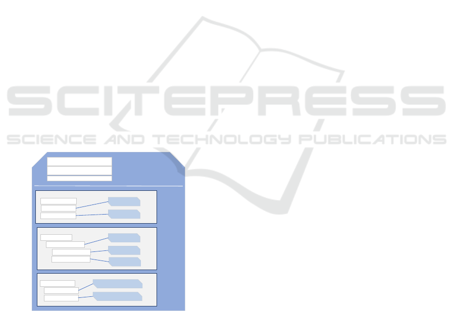
From a high-level point of view, an AAS is structured
as depicted in Figure 1. It is composed by a header
containing all the information relevant to the
identification of both AAS and asset, and a Body
containing all the inherent information of the asset in
the form of properties and functions (also referred as
operations) (Platform Industrie 4.0, 2016).
Asset Identification
AAS Identification
...and others
Administration Shell
Header
Body
Submodel 1 e.g. energy efficiency
Property 1.1
Property 1.1.1
Property 1.1.2
Information
Function
Submodel 2 e.g. positioning mode
Property 2.1
Property 2.1.1
Property 2.1.1.1
Information
Function
Property 2.1.1.2
Function
Submodel 3 e.g. CAD model
Property 3.1
Property 3.1.1
Property 3.1.2
Information (CAD)
Information (CAD)
Figure 1: Structure of the AAS.
Properties are defined as classified and mutually
independent characteristics of systems that can be
associated with values (Kampert, 2012). Functions,
instead, are capabilities and actions that an asset
performs. Properties and functions are collected
under so-called sub models, each of which describe a
specific aspect relevant to an asset, like energy
efficiency, positioning, documentation, drilling,
maintenance, among others.
In November 2019, the initiative Platform
Industrie 4.0 released an AAS metamodel specifying
how structure the information inside the AAS. In
(Platform Industrie 4.0, 2019) the AAS metamodel is
presented as a UML class diagram, defining all the
“building blocks” that must be used to structure
internally the AASs of every possible asset.
Since the same entities of the metamodel may be
used to define elements representing different
concepts (e.g. modelling “height” or “rotation speed”
as properties), such entities must be semantically
annotated. Sub models, properties or functions
composing an AAS contains a special attribute,
named semanticId, pointing to a semantic definition
contained in an external semantic repository. The
term “semantic repository” identifies any sort of
database or catalogue where the semantic definitions
reside, like IEC Common Data Dictionary (CDD) or
eCl@ss.
AAS is important also to realise of one of the
main features that an I4.0 Component provides,
which is “nestability” as discussed in (Kagermann,
2013). In fact, the AAS of a composite component
reflects the composition relationship referencing the
ASSs of its components.
3.2 AAS Interface
The AAS is a software entity providing its internal
information to the external world by means of a
standardised API. Internal information is structured
according to the AAS metamodel, as discussed
previously. The API of an AAS provides a CRUD-
oriented interface, thus data are accessible by a
communication network so that an external client can
either retrieve or manage the data of interest making
simple requests to the relevant AAS.
In general, RAMI 4.0 do not put any constraints
about the location of an AAS: it may be embedded
directly on a smart device or deployed in a completely
different location, even though a connection with the
asset may be maintained.
4 PROPOSAL OF A PREDICTIVE
MAINTENANCE MODEL
The model presented in this paper realises a novel
approach for the definition of a PdM solution in the
context of the fourth industrial revolution. Such an
Predictive Maintenance Model based on Asset Administration Shell
683
approach is based on the concept of the so-called
Logical Block (LB). A LB is a modular element that
groups functionalities relevant to a specific aspect of
the PdM. The entire set of the functionalities of a LB
generalises specific operations for the PdM process,
regardless of how such operations are actually
implemented. LBs and their functionalities are meant
to be modular and cooperating elements in order to
describe a PdM solution (entirely or part of it) in a
generic manner without considering implementation
details. Describing a device in terms of its LB
functionalities permits the definition of a role for that
device. Such role identifies a sort of equivalence class
between all the devices implementing the same
functionalities. Therefore, this makes the replacement
of a device with an equivalent one seamless from the
point of view of the PdM program, without any
disruptive effect on it.
Authors decided to use the concept of AAS and
I4.0 Component to cope with the problem of
heterogeneity of technologies present at OT level, as
discussed in the previous sections. The structure of
the AAS allows the realisation of LBs and their
functionalities as will be discussed further. The
common interfaces and the semantically enriched
information exposed by the AAS make this last the
foundation of the PdM model here presented. In fact,
AAS achieves interoperability creating a sort of
abstraction layer at the lowest level of the production
infrastructure and thus allows a PdM program to be
adapted to production reconfiguration.
The PdM model will be presented following a
bottom-up approach, starting with the description of
the most fine-grained elements and ending with the
high-level view of the model highlighting the
interactions between its components.
4.1 Logical Blocks for PdM
As said before, a Logical Block abstracts all the
functionalities required for the PdM process, thus
generalises and modularises the description of the
PdM solution. In this way, the implementation of
same functionalities and operations can be done using
different technologies and approaches but exposed
with a uniform interface. The LBs here presented
have been defined considering the common aspects of
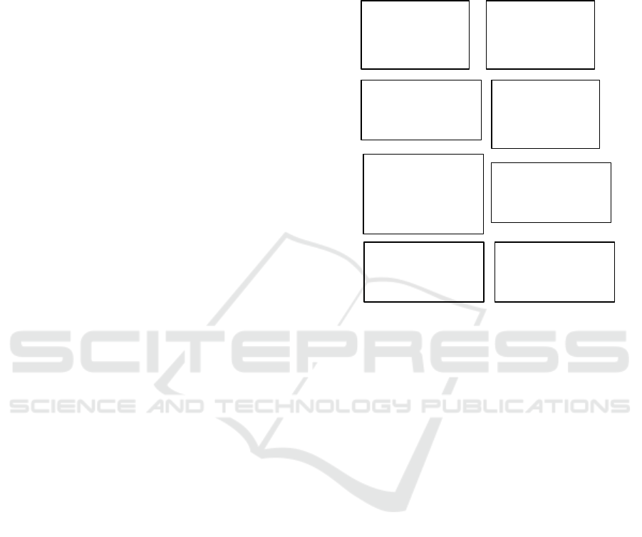
the state of the art of PdM. Figure 2 points out the LBs
described in the following subsections.
4.1.1 Data Acquisition
This LB provides all the functionalities required to
access data coming from sensors or devices. It
involves functions like the conversion of the output
of a transducer to a digital parameter representing the
physical quantity. Such digital values may be
enhanced with more quality parameters, like
calibration or timestamp.
Data Acquisition
- Get measured values
- Convert analog value
- Set measure unit
- Set sensitivity
- ...
Aggregation
- Calculate mean, rms, etc
- Interpolate values
- Set aggregation params
- ...
Data Manipulation
- Filter values
- Apply FFT
- Remove noise
- Transform values
- ...
Schedule
- Set maintenance task
- Get task information
- Get maintenance history
- ...
Status
- Set operating mode
- Set maintenance mode
- Get status log
- ...
Configuration
- Set LBs parameters
- Call LB's operations
- Save/load configurations
- ...
Prediction Model
- Manage model
- Train model (AI)
- Get forecasts
- Set model parameters
- ...
Maintenance
Decision-making
- Set decision algorithm
- Create maintenance task
- Commit technician
- Get decisions history
- ...
Figure 2: The LBs implementing generic functionalities
related to PdM aspects.
4.1.2 Data Manipulation
This LB defines all the operations that perform
analysis on signals and computes meaningful
descriptors from raw measures, which usually come
from the LB Data Acquisition (DA). It also performs
transformations on signals, like filtering or errors
correction, and applies algorithms for features
extraction.
4.1.3 Configuration
This LB provides an interface exposing parameters
and management functions for the configuration of
other data-processing LBs. For instance, some
configurations for the block DA may include the
relative position of transducers, monitoring polling
rates and calibration parameters, among others. Of
course, parameters and functionalities of LB
Configuration may be strictly dependant from the
implementation of the other LBs. For instance,
considering a block DA implemented using OPC UA
(IEC 62541) and the Subscription mechanism for data
retrieval, a LB Configuration may be used to
configure parameters relevant to the publishing
interval or sampling interval.
ICEIS 2021 - 23rd International Conference on Enterprise Information Systems
684

4.1.4 Aggregation
This LB contains all the functionalities required for
data aggregation of all the different data coming from
monitored devices. Such a block may include
mechanisms of Sensor Data Fusion when, for
example, the data monitored from a complex device
come from sub-devices or sensors composing it. This
perfectly fits with the concept of AAS because it
allows the representation of complex devices by
means of composition of the AASs of their sub-
devices. In these terms, for instance, the Aggregation
block implemented in the AAS of a composite device
uses data coming from the DM or DA blocks
contained in the AASs of the component devices.
Furthermore, input data of an Aggregation LB may
come from other Aggregation blocks, hence realising
an aggregation hierarchy, which is required to
manage the large amounts of data coming from
sensors.
4.1.5 Prediction Model
All the functionalities and facilities needed for the
diagnostics and prognostics of the monitored
machinery are implemented in this LB. For instance,
this LB may consist of a neural network-based model
or decision tree-model. When it is possible, the
models here provided are trained using historical data
of both conditions and faults of machines, eventually
manipulated using the outputs of the other LBs
discussed previously. Furthermore, the models may
be constantly trained using data gathered in real time
from AASs or forecast errors may be used to improve
the accuracy of the model. It is worth noting that
technical personnel working on data analysis and the
tools they use are considered also entities
implementing functionalities of the block Prediction
Model.
4.1.6 Maintenance Decision-making
This LB involves all the functionalities required to
process the data coming from the block Prediction
Model to schedule appropriate maintenance actions
for the monitored machine. Therefore, this block
involves the facilities to schedule maintenance tasks,
to commit eventually the available technicians for the
maintenance, and to change the operational state of
the machine (i.e. changing the operational state from
“working” to “maintenance”). All these kinds of
operations change information in the proper AAS sub
model of the relevant devices.
In general, most of the functionality provided by
a Computer Maintenance Management System may
be considered part of the Maintenance Decision-
making block. It is worth noting that the output of this
LB may be used as a feedback for the Prediction
Model block to adjust the accuracy of the model
adopted or check its correctness.
4.1.7 Schedule
This LB collects all the facilities to manage the
information relevant to the maintenance tasks. For
instance, some information may include the date and
the duration of the maintenance task and the operator
assigned to it. This LB also includes the history of
maintenance operations as it can give an estimation
about the condition of the machine to consider or, in
the worst case, whether a replacement with a new one
occurred.
4.1.8 Status
This LB maintains the information about the status of
the machine. In particular, it explicitly shows when
the machine is in operating mode or in maintenance
mode. This information may be useful to check the
general status of the plant or to label eventual data still
being collected from the machine even during a
maintenance operation.
4.2 AAS Sub Model for PdM
LBs can be realised following different standards or
guidelines; for instance, functionalities for condition
monitoring of machines may be based on standard
like VDMA 24582 or ISO 17359.
In this paper it has been assumed that I4.0-
Components implement all the functionalities of their
LBs inside specific sub models. Such functionalities
are implemented inside the sub models as properties
and operations, both semantically annotated. The
main idea in Industry 4.0 is having a standardised sub
model definition for every relevant aspect of an asset
but, up to now, no standardised sub model definition
has been released. The model here proposed involves
the definition of new AAS sub models containing
well-known LB functionalities, so that some of the
steps of the PdM process may implemented in a
common and standardised manner inside I4.0-
Components. Furthermore, since AAS allows for
composition, functionalities in sub model may be
represented as composition of functionalities of the
AASs of sub-devices or logically underlying devices.
For instance, configuration functionalities of a high-
level device may be represented as a composition of
several configuration functionalities of underlying
devices.
Predictive Maintenance Model based on Asset Administration Shell
685
The two sub models presented and discussed in
the following cover all the functionalities required for
the condition monitoring and for the scheduling of
maintenance operations of a device; they are named
“Condition Monitoring” and “Maintenance”,
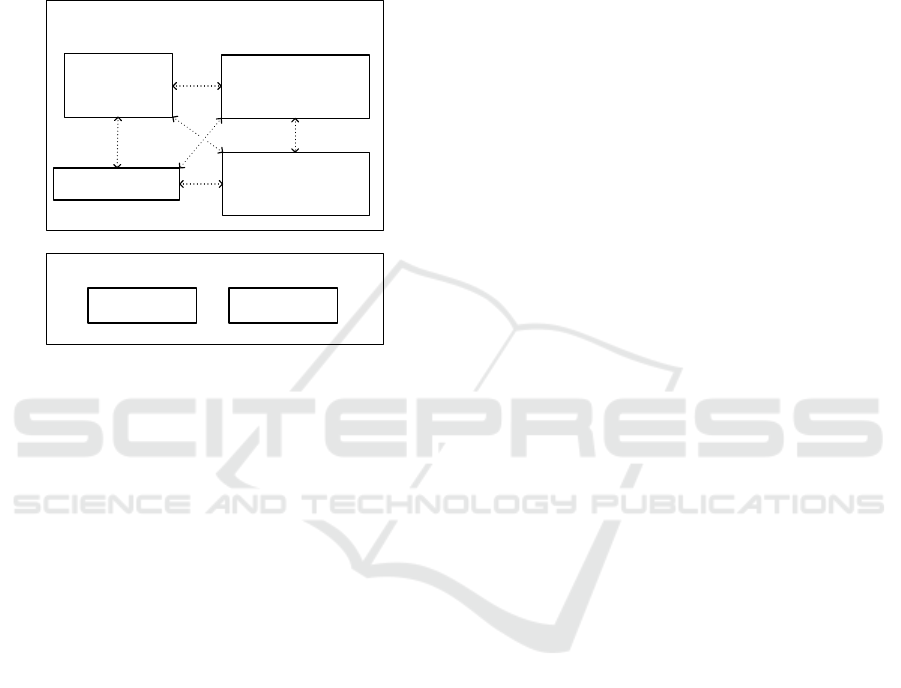
respectively. Figure 3 shows the LBs implemented
internally by the two sub models highlighting the
relationships between them.
Submodel: Condition
Monitoring
Sub model: Mainten ance
Data
Acquisition
Configuration
Data
manipulation
Schedule Status
Aggregation
Figure 3: Sub model definition for Condition Monitoring
and Maintenance and the LBs they implement.
As shown in figure, the sub model Condition
Monitoring implements the LBs Data Acquisition
(DA), Data Manipulation (DM), Configuration and
Aggregation. The presence of the depicted LBs in the
sub model is not mandatory. Whether a LB is
implemented or not depends on the specific case in
examination. For instance, a smart sensor may not
implement the functionalities of the block
Aggregation inside its AAS, whereas for an industrial
gateway is quite common implementing aggregation
functionalities. All the LBs in the Condition
Monitoring sub model may interact to each other, as
depicted in figure by means of dotted arrows. Such
interactions represent data flows, events dispatching,
function calls or parameter settings.
The sub model Maintenance implements the
functionalities of the block Schedule and Status. In
general, the scope of this sub model involves
everything concerning the maintenance tasks and
operational condition of the device.
The blocks Prediction Model and Maintenance
Actions are not considered inside the sub models
definitions here provided because such high-level
functionalities with high-demanding computational
requirements may not be easily implemented in I4.0-
Components at OT level. It is worth noting that this
assumption is not a limitation, because an AAS of a
high-specialised tool may implement, if the solution
requires so, the Prediction Model functionalities
inside a well-known sub model.
4.3 Description of the PdM Model
From a high-level point of view, the PdM model is
divided in two main parts: Operational Infrastructure
(OI) and Prognostics & Maintenance Management
Infrastructure (PMMI). The former encompasses all
the elements of the plant which are part of the PdM
solution and involved in the data collection and data
manipulation processes required for prognostics.
Examples of such elements are the machines to be
maintained, industrial gateways, industrial PCs, but
even high-level tools like MES and ERP may be
considered being part of OI. The latter, instead,
encompasses all the elements of the PdM solution
using data coming from OI to forecast machine
failures and schedule maintenance actions. Examples
of such elements may be AI models (e.g. Recurrent
Neural Network), tools for data analysis and software
for the maintenance management.
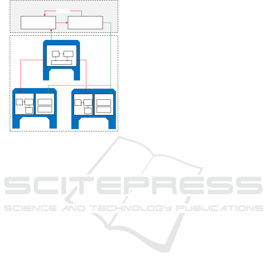
The structure of the PdM model is depicted in
Figure 4 highlighting the relationship between
components and the data streams from low-level
devices to the PMMI elements for the decision-
making task, depicted by red arrows. Furthermore,
the figure shows how the topmost components
interact with the maintained devices to set their
operational status and commit maintenance tasks.
This procedure is depicted with green arrows.
As shown in figure, OI consists of I4.0-
Components providing both data for the condition
monitoring (e.g. production machinery that will
require maintenance, sensors) and operations for data
manipulation required from the first steps of the PdM
process (e.g. Smart Device, Industrial PC, Gateway).
In general, what belongs to Operational Technology
(OT) is considered part of the OI. Therefore, devices
like sensors, actuators, machinery, but also PLC,
SCADA, DCS, may be considered part of OI, but also
Information Technology (IT) elements like databases,
industrial PCs, or edge devices like gateways. The
presence of AAS is mandatory for the devices at the
lowest levels of the infrastructure because such
devices features a high degree of heterogeneity in the
technologies and data representation adopted.
Therefore, the AAS realises the abstraction layer
needed to achieve interoperability at that level. The
only requirement in the PdM model is that every PdM
component that need to interact with an I4.0-
Component need to communicate with the AAS API
and thus understand its semantics.
ICEIS 2021 - 23rd International Conference on Enterprise Information Systems
686
Condition
Monitoring
Maintenance
DA
Config
DM
Schedule
Status
AAS Device
Maintenance
DA
Config
DM
Schedule
Status
AAS Device
Condition Monitoring
Config
DM
AAS Aggregator
Aggregation
Prognostics & Maintenance Management Infrastracture
Prediction
Model
Maintenance
Decision-making
Feedback
Operational
Infrastracture
Condition
Monitoring
Figure 4: AAS-based PdM model for predictive
maintenance.
PMMI consists of IT elements and software
components providing all the functionalities needed
for data analysis, failures prediction, and scheduling
of the maintenance tasks. The nature of such
components is not specified but they are described
only in terms of the functionalities they provide (i.e.,
their LBs). Such functionalities may be implemented
on devices of the Information Technology (IT)
infrastructure and/or in Cloud (in case of Cloud-based
PdM). For this reason, it makes no sense speaking of
“devices” because at this level what really matters are
functionalities, and their implementation strictly
depends on the solution adopted for PdM. For
instance, the prediction functionalities defined for
PMMI may be implemented either by a Recurrent
Neural Network (Artificial Intelligence-based
solution) or by a physical operator consulting a visual
tool for data analysis; even if the former is a software
component and the latter is a human being, both of
them are considered entities of the PMMI because
realises the same functionalities but in different ways.
Since entities implementing functionalities in PMMI
interact and use data coming from OI entities, it
follows that they must understand the AAS API and
data of the OI entities.
The differentiation between Device and
Aggregator depicted in figure is not formal and is
used just to clarify which role an entity plays in the
OI. The role an entity plays depends on the LB it
implements. For instance, AAS Device in Figure 4
identifies the role of a generic Device that provides
condition monitoring features to evaluate is health
condition and eventually schedule maintenance tasks.
AAS Aggregator, instead, identifies the role of a
device that is not a direct subject of the maintenance
process but required for it. In particular, the LBs it
implements suggest that the role of AAS Aggregator
is that of collecting data coming from different
underling devices with the role of “Devices” and do
some sort of manipulation (e.g. data aggregation,
sensor data fusion) before sending them to other
entities.
The role of an entity can be discriminated just
looking at the LBs and the relevant functionalities it
implements. This aspect of the proposed PdM model
allows the definition of a sort of equivalence classes
for PdM components because such roles are defined
in terms of collection of generic PdM functionalities.
The possibility of describing roles for components of
a PdM solution gives the great advantage of
seamlessly replace a device with another device of the
same role during a re-configuration in the production,
without affecting the PdM program.
5 CONCLUSIONS
PdM solutions can be adapted to production re-
configuration if satisfy two main requirements: a
model to describe the solution in terms of generic
functionalities not depending from the approach used
to realise PdM and an abstraction mechanism for all
the different technologies adopted for the PdM
implementation. This paper proposes a PdM model
defining a new approach to satisfy both, whose
advantages rely on both the concept of LB and AAS.
The former is a conceptual group of functionalities
related to the same aspect of a PdM solution and
allows the definition of roles for the components of
the maintenance program, which enable both easy
replacement and changings in the PdM solution in a
seamless manner. The latter, instead, provides an
abstraction layer for the heterogeneity of devices and
technologies adopted (especially in the brownfield)
improving the degree of integration between PdM
components and a common structure to the
information and operation featured by devices.
As discussed in the paper, the structure of the
AAS perfectly fits for the realisation of LB
functionalities using semantically annotated
properties and functions inside sub models. Both the
LBs and AASs adopted in the PdM model here
presented allow the definition of maintenance
programs in a way that improves the level of
flexibility in production. PdM solutions based on
different approaches to PdM may be represented
Predictive Maintenance Model based on Asset Administration Shell
687

according the proposed model: all the relevant part of
the solution may be described in terms of generic LB
functionalities, defining the roles that such PdM
components play in the whole PdM solution.
Generalisation dictated by the model allows easy
reconfiguration and extensibility of the production
systems, increasing the integration of all the different
parts of a PdM solution.
ACKNOWLEDGEMENTS
This paper belongs to a research path funded by
University of Catania (PIA.CE.RI. 2020-2022 Linea
2—GOSPEL Project—Principal investigator A.
Costa—Code 61722102132).
REFERENCES
Ahmad, R., & Kamaruddin, S., 2012. An overview of time-
based and condition-based maintenance in industrial
application. Computers & Industrial Engineering, pp.
135-149.
Birtel, M., Mohr, F., Hermann, J., Bertram, P., &
Ruskowski, M., 2018. Requirements for a Human-
Centered Condition Monitoring in Modular Production
Environments. IFAC-PapersOnLine, pp. 909-914.
Cavalieri, S., & Salafia, M. G., 2020 (2020a). Asset
Administration Shell for PLC Representation Based on
IEC 61131–3. IEEE Access, pp. 142606-142621.
Cavalieri, S., & Salafia, M. G., 2020 (2020b). Insights into
Mapping Solutions Based on OPC UA Information
Model Applied to the Industry 4.0 Asset Administration
Shell. Computers, 9(2), 28.
DIN, 2016. DIN SPEC 91345:2016-04, Reference
Architecture Model Industrie 4.0 (RAMI4.0). Berlin:
Beuth Verlag GmbH.
Groba, C., Cech, S., Rosenthal, F., & Gossling, A., 2007.
Architecture of a Predictive Maintenance Framework.
6th International Conference on Computer Information
Systems and Industrial Management Applications
(CISIM'07). Minneapolis, MN, USA.
Infosys, 2018. Interoperability between IIC architecture &
Industry 4.0 Reference Architecture for Industrial
Assets. Retrieved 07 13, 2020, from
https://www.infosys.com/engineering-services/white-
papers/documents/industrial-internet-consortium-
architecture.pdf
Jardine, A. K., Lin, D., & Banjevic, D. (2006). A review on
machinery diagnostics and prognostics implementing
condition-based maintenance. Mechanical Systems and
Signal Processing, pp. 1483-1510.
Kagermann, H., Wahlster, W., & Helbig, J., 2013.
Recommendations for implementing the strategic
initiative INDUSTRIE 4.0. Final report of the Industrie
4.0 Working Group. Acatech, Frankfurt am Main.
Kampert, D., & Epple, U., 2012. Modeling asset
information for interoperable software systems. IEEE
10th International Conference on Industrial
Informatics. Beijing, China.
Khana W. Z., Rehmanb M. H., Zangotic H. M., Afzald, N.
Armia M. K., Salah K, 2019. Industrial Internet of
Things: Recent Advances, Enabling Technologies, and
Open Challenges. Computers & Electrical Engineering
81. DOI: 10.1016/j.compeleceng.2019.106522.
Lang, D., Grunau, S., Wisniewski, L., & Jasperneite, J.,
2019. Utilization of the Asset Administration Shell to
Support Humans During the Maintenance Process.
IEEE 17th International Conference on Industrial
Informatics (INDIN). Helsinki.
Liao, Y., Deschamps, F., Loures, E. de F. R., & Ramos, L.
F. P., 2017. Past, present and future of Industry 4.0—A
systematic literature review and research agenda
proposal. International Journal of Production
Research, pp. 3609–3629.
Motaghare, O., Pillai, A. S., & Ramachandran, K., 2018.
Predictive Maintenance Architecture. IEEE
International Conference on Computational Intelligence
and Computing Research (ICCIC). Madurai, India.
Moyne, J., Qamsane, Y., Balta, E. C., Kovalenko, I., Faris,
J., Barton, K., & Tilbury, D. M., 2020. A Requirements
Driven Digital Twin Framework: Specification and
Opportunities. IEEE Access,
pp. 107781-107801.
Panda, S. K., Schröder, T., Wisniewski, L., & Diedrich, C.
(2018). Plug Produce Integration of Components into
OPC UA based data-space. IEEE 23rd International
Conference on Emerging Technologies and Factory
Automation (ETFA). Turin, Italy.
Platform Industrie 4.0, 2016. Structure of the
Administration Shell - Continuation of the
Development of the Reference Model for the Industrie
4.0 Component. Berlin: Federal Ministry for Economic
Affairs and Energy (BMWi).
Platform Industrie 4.0, 2018. The Standardisation Roadmap
of Predictive Maintenance for Sino-German Industrie 4.
Federal Ministry of Economic Affairs and Energy.
Platform Industrie 4.0, ZVEI, 2019. Details of the Asset
Administration Shell.
Tantik, E., & Anderl, R., 2017. Potentials of the Asset
Administration Shell of Industrie 4.0 for Service-
Oriented Business Models. Procedia CIRP, pp. 363–
368.
Strauß, P., Schmitz, M., Wöstmann, R., & Deuse, J., 2018.
Enabling of Predictive Maintenance in the Brownfield
through Low-Cost Sensors, an IIoT-Architecture and
Machine Learning. IEEE International Conference on
Big Data (Big Data). Seattle, WA, USA.
Xu, L. D., Xu, E. L., & Li, L., 2018. Industry 4.0: State of
the art and future trends. International Journal of
Production Research, pp. 2941–2962.
Wollschlaeger, M., Theurich, S., Winter, A., Lubnau, F., &
Paulitsch, C., 2015. A reference architecture for
condition monitoring. IEEE World Conference on
Factory Communication Systems (WFCS). Palma de
Mallorca, Spain.
ICEIS 2021 - 23rd International Conference on Enterprise Information Systems
688
