
Rapid Light Flash Localization in SWIR using Compressed Sensing
Andreas Brorsson
a
, Carl Br
¨
annlund
b
, David Bergstr
¨
om
c
and David Gustafsson
d
FOI - Swedish Defence Research Agency, C4ISR , Link
¨
oping, Sweden
Keywords:
Compressive Sensing, CS, Single Pixel Imaging, Flash Localization,Single Pixel Target, SWIR, Total
Variation, Muzzle Flash.
Abstract:
A high-resolution single pixel camera for long range imaging in the short-wave infrared has been evaluated
for the detection and localization of transient light flashes. The single pixel camera is based on an InGaAs
photodiode with a digital micromirror device operating as a coded aperture. Images are reconstructed using
compressed sensing theory, with Walsh-Hadamard pseudo-random measurement matrices and fast Walsh-
Hadamard transform for localization. Our results from experiments with light flashes are presented and the
potential use of the camera for muzzle flash detection and localization is discussed.
1 INTRODUCTION
The primary signal modalities used to detect snipers
are acoustic signal, optical signal from the muzzle
flash (visual and IR) and pre-shot laser retro-reflection
from the optical sight. In the visual spectrum, the
muzzle flash can be extremely weak and hard to de-
tect, especially in daylight and in particular with sig-
nature suppressors mounted. The MWIR range (3
- 5 µm) would therefore be seen as the best choice
for a hostile fire indication (HFI) system (Trzaskawka
et al., 2010; Kastek et al., 2011). The MWIR range
is however associated with larger size, weight, power
requirements and cost (e.g. higher SWaP-C). Systems
operating in the short-wave infrared (SWIR) bands
0.8 - 1.7 µm and 1.1 - 2.5 µm have advantages of po-
tentially lower SWaP-C. The former SWIR band is
usually preferred due to the availability of uncooled
InGaAs FPAs in this spectral range. An example of
the spectral distribution of a 50 caliber gun and im-
ages of a sniper rifle at 1000 meters in SWIR and
MWIR can be seen in Figure 1.
This paper presents an initial concept of an HFI
and sniper sight optics detection system, using Com-
pressive sensing (CS) and a low cost single pixel cam-
era (SPC) with a background subtraction method im-
plemented. Because a very fast photo diode collects
the light in the SPC, the temporal resolution of the
a
https://orcid.org/0000-0002-3922-9334
b
https://orcid.org/0000-0002-4047-2083
c
https://orcid.org/0000-0003-2414-4482
d
https://orcid.org/0000-0002-4370-2286
muzzle flash is not limited by the frame rate. SWIR
images of a scene, including the sniper, can be gen-
erated while it also can detect and localize fast events
such as muzzle flashes. Also, the unique temporal
signature of the flash can be measured directly in the
detector signal, thus suppressing false alarms which
is important for an operational system. Background
reduction is performed directly on the raw data with
data captured just before or after the fast event, mak-
ing the data of the flash even sparser. Because the
data of the flash is highly sparse, reconstruction of
the image is possible using TVAL3 (Total Variation
Augmented Lagrangian Alternating Direction Algo-
rithm). Restoration of the image to locate the flash is
performed after it is detected and discriminated, thus
minimizing the power usage. The system may also
be used for optics (or cat’s eye) detection if a laser
is irradiating the scene, which means that a sniper
may be detected and localized pre-shot. (Trzaskawka
et al., 2010; Br
¨
annlund et al., 2013) This functionality
is to some degree demonstrated in the paper, when a
small reflector is irradiated with a 1550 nm laser. It
may also be possible to find the distance to the target
by measuring the time-of-flight of the reflection, but
this functionality is not demonstrated as the focus of
this paper is on muzzle flash detection. The temporal
signature of a muzzle flash in various spectral bands
can be seen in Figure 2. As can be seen, the flashes
in SWIR are typically less than 1 ms long (Svensson
et al., 2011).
566
Brorsson, A., Brännlund, C., Bergström, D. and Gustafsson, D.
Rapid Light Flash Localization in SWIR using Compressed Sensing.
DOI: 10.5220/0010386605660573
In Proceedings of the 16th International Joint Conference on Computer Vision, Imaging and Computer Graphics Theory and Applications (VISIGRAPP 2021) - Volume 4: VISAPP, pages
566-573
ISBN: 978-989-758-488-6
Copyright
c
2021 by SCITEPRESS – Science and Technology Publications, Lda. All rights reserved
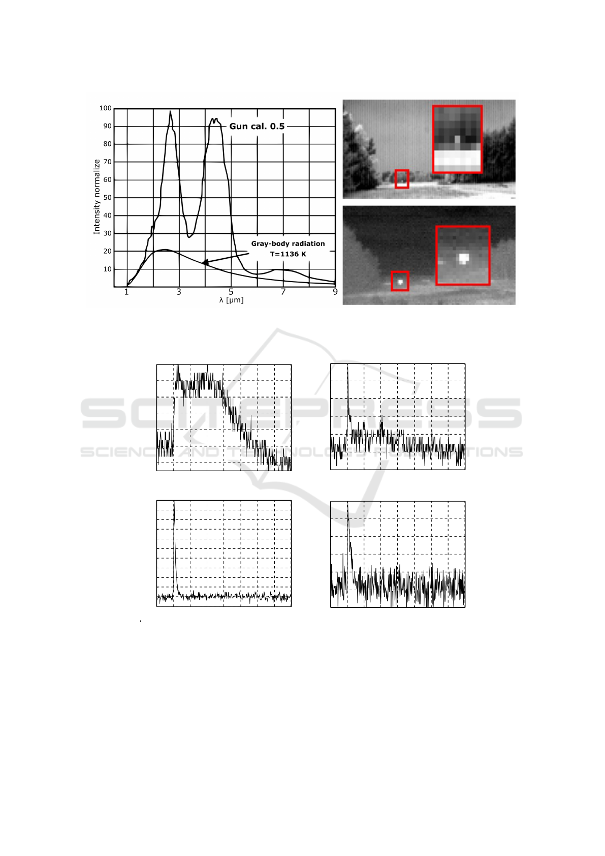
Figure 1: Left: The spectral distribution from a secondary flash. The weapon has a caliber of 0.5 (barrel length 36 in).
(Trzaskawka et al., 2010) Top right: Muzzle flash from a sniper rifle at 1000 meters recorded in SWIR (0.8-1.7 µm). Bottom
right: Same flash in MWIR (3-5 µm). The red rectangles show enlargements at the rifle position (Krieg et al., 2016).
Time [s]
Time [s]
Time [s]
Time [s]
0.42 0.43 0.44 0.45 0.46
0.42 0.43 0.44 0.45 0.46
0.42 0.43 0.44 0.45 0.46
0.42 0.43 0.44 0.45 0.46
0
0.4
0.8
0
0.4
0.8
Band 4
Band 5
Band 1
Band 3
0
0.4
0.8
0
0.4
0.8
Intensity
Intensity
Intensity
Intensity
Figure 2: The intensity recorded for a 7.62 cal gun for multiple spectral bands, shown during a 40 ms duration and normalized
to the peak value. Band 1 is 0.35 - 0.65 µm, band 3 is 1.46 - 1.79 µm, band 4 is 2.13 - 2.57 µm and band 5 is 3.0 - 4.80 µm. In
the 0.35 - 0.65 µm band, only scattered light from the sun and the flash itself was observed (Svensson et al., 2011).
Rapid Light Flash Localization in SWIR using Compressed Sensing
567

2 RELATED WORK
In (Br
¨
annlund et al., 2013), a combined hostile fire
and optics detection system was tested, using a laser
illuminator and a high speed FPA camera in SWIR.
In (Krieg et al., 2016), a system using 19 single ele-
ment detectors to detect muzzle flashes was demon-
strated. Additionally, two acoustic sensors were in-
tegrated to reduce false alarms. Gil Tidhar proposes
a hostile fire indication (HFI) system with two FPA
sensors, the first operating in SWIR and the second
one in the visible band. With this solution sun-glints
and other light sources such as car headlamps can be
cancelled out, as the spectra of such sources is typi-
cally different to that of a muzzle flash (Tidhar et al.,
2009). Trzaskawka et al. presents an initial concept
of a cooled electro-optical sensor unit in MWIR for
sniper detection purposes and discuss the characteris-
tics of muzzle flashes (Trzaskawka et al., 2010).
Conventional cameras capture the scene by mea-
suring the light at each of the thousands or millions
of pixels. In Compressed Sensing (CS), a relatively
small number of measurements from the scene is
combined with sparse reconstruction procedures to
recover an image using only a single or a reduced
number of pixel detectors. CS exploits the fact that
natural images are compressible or sparse in some ba-
sis and therefore only a few measurements relative
to the image resolution are needed (sub-Nyquist) to
reconstruct the image. Two constraints must be ful-
filled in order to utilize CS sampling: the image in-
formation needs to be compressible and the measure-
ment matrix need to be incoherent with the sparse
transform. The first constraint is fulfilled because it
is known that natural images are compressible, us-
ing for example JPEG or JPEG2000 compression al-
gorithms. The second constraint is fulfilled using a
measurement matrix with a random characteristic. In
CS, a high resolution image can be acquired at sub-
Nyquist sampling rates while using smaller, cheaper
and lower bandwidth components but with the ex-
pense of a longer acquisition time compared to stan-
dard cameras (Wakin et al., 2006; Takhar et al., 2006;
Takhar et al., 2008).
In (Chen et al., 2017) a method to detect light
flashes in raw data using a CS-based single pixel cam-
era (SPC) and a sliding window calculation process is
presented. They succeed in detecting 25 ms anoma-
lies with an intensity 4 times higher than the back-
ground. In previous work Br
¨
annlund et al. presented
an SPC in SWIR which can detect and localize light
flashes from a minimal number of measurements and
discuss a muzzle flash detection system using a high
speed DMD (Br
¨
annlund et al., 2019).
3 SINGLE PIXEL CAMERA
ARCHITECTURE
Our platform consists of a digital micromirror device
(DMD) (Vialux V-7000, 1024 ×768, 22.7 kHz) and
a large area detector InGaAs photodiode (Thorlabs
PDA20C/M, 0.8-1.7 µm). The light from the ”active”
micromirrors is collected by a ”light bucket” - the de-
tector and a 50 mm fixed focal length lens (f/1.4, 0.8-
2.0 µm). A single plano-convex lens (Thorlabs, f=200
mm, D=75mm, 1.05-1.7 µm) focusing the scene onto
the DMD, see Figure 3. A visual spectrum reference
camera is also mounted viewing the DMD to simplify
focusing of the system.
The single pixel sensor captures the scene by mea-
suring the light intensity focused onto the detector re-
flected from the DMD (Digital Micromirror Device),
or another SLM (Spatial Light Modulator). The DMD
can quickly change patterns to obtain new measure-
ments. M measurements are sampled to reconstruct
an image with N pixels, where M N. Each ele-
ment in the measurement matrix is encoded as one or
zero (or negative one, with two sensors) which corre-
sponds to the individual DMD mirror state. The CS
sampling model is defined as
y = Φx +ε, (1)
where x is the scene considered as an image rear-
ranged as a one-dimensional array with N pixels, y
is the sampled signal with M measurements, Φ is the
measurement matrix and ε is the noise. CS states
that M can be relatively small compared to N, where
the number of measurements needed to reconstruct an
image depends on the sparsity of the image. Using
an SPC where noise contaminates the signal and the
scene may not be completely stationary, the number
of measurements needed will increase in proportion to
the noise and the dynamics in the scene. Permutated
Sequence Ordered Walsh-Hadamard matrix (WHM)
are used as measurement matrices, which replaces
matrix multiplication in Equation 1 with the fast
Walsh-Hadamard transform (FWHT). The FWHT is
both faster than matrix multiplication and eliminating
the need to store the measurement matrices in com-
puter memory. WHM has approximately the same
characteristics and properties as an independent and
identically distributed (i.i.d.) random matrix but gen-
erally needs a higher number of measurements for ex-
act reconstruction of the image. Research has how-
ever shown that there is no significant loss in recov-
ery of the image relative to the i.i.d. random mea-
surement matrix (Cai Zhuoran et al., 2013). The total
variation (TV) based TVAL3 is used for image recon-
struction. Natural images often contain sharp edges
VISAPP 2021 - 16th International Conference on Computer Vision Theory and Applications
568
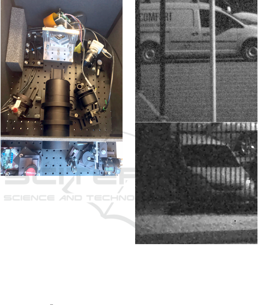
Figure 3: The single pixel camera architecture used in this
work. The optics, DMD, reference camera, the single pixel
sensor and laser are shown.
and piecewise smooth areas which the TV regulariza-
tion algorithm is good at preserving. The main differ-
ence between TV and other reconstruction algorithms
is that TV considers the gradient of signal to be sparse
instead of the signal itself, thus finding the sparsest
gradient (Li, 2010).
The SPC architecture is also built with an optional
secondary detector which measure the complement of
the first sensor. Previous research show that similar
reconstruction results can be achieved with approxi-
mately half the number of patterns compared to one
sensor. The research also show that the reconstruc-
tion became more stable with dynamics in the scene
and vibrations on the camera itself compared to only
one sensor. In summary, by using two sensors, the in-
formation of the scene sampled is doubled while the
noise increases by
√
2 in the combined signal. The
benefit of using two sensors in the context of light
flash localization is that on average a detector only
sees half of the light event per DMD pixel. If it is de-
sired to identify the signal based on a signature, half
of the information is lost, but can be complemented
using the other detector (Oja and Olsson, 2019).
Figure 4: Two images of cars at 512x512 (top) and 256x256
(bottom) pixel resolutions at 350 m. Subsampling ratios are
30% and 40%, respectively. In the bottom image a fence can
be seen in the foreground (seen as thin horizontal lines).
4 TARGET DETECTION AND
LOCALIZATION SYSTEM
The localization systems and target application de-
scribed in this article rests on an edge case of CS the-
ory and is enabled by the high speed DMD pattern
rate. The spatial resolution of the signal to be located
is bound to the temporal resolution (the length of the
signature) by
M ≥ k log(N/k ), (2)
Rapid Light Flash Localization in SWIR using Compressed Sensing
569

where k is the number of ”pixels” the light flash is vis-
ible in and M is the minimum number of patterns re-
quired to reconstruct the signal without noise (Takhar
et al., 2008). The minimum temporal length of the
light flash is
t ≥
M
DMD pattern rate
, (3)
which for example means t ∼0.3−1.0 ms, depending
on the pixel spread in 32 ×32 resolution. In Equa-
tion 2 it is assumed that the only information in the
signal is the light flash, in order to extract the signal a
method with background reduction was implemented
which is described in Section 4.1. With the help
of the background reduction, in principle, all back-
ground information from static objects in the scene is
removed, while dynamic information in the scene that
has a longer temporary signature than the light phe-
nomenon can be filtered out. After the background
reduction, the signal is analyzed by a detection algo-
rithm. The detection algorithm can for example use
a matched filter to compare the background reduced
signal against a known signature, which is described
in Section 4.2. Only if a match with high probability
is found the signal is reconstructed for localization. In
the localization step, different reconstruction methods
can be used depending on the signals temporal length
and pixel spread, which is described in Section 4.3.
4.1 Background Subtraction
The background reduction has been implemented by
repeating a fixed number of patterns on the DMD dur-
ing the measurement. The number of patterns in the
repeating window is set to double the temporal length
of the light phenomenon. It is desirable that the win-
dow is as small as possible so that potential dynamics
in the scene is keept to a minimum. From the mea-
sured data y, a new vector is created that contains
background-reduced data by calculating the residual
between two corresponding patterns according to,
y
ρ(i)
= |y
i
−y
i+w
|, (4)
where y
ρ
is the background reduced signal and w is
the number of patterns in the window. Assuming that
a light flash has occurred in one of the windows the
equation can be expanded to
y
ρ(i)
= |y
i
−y
i+w
|
= |(y
δ(i)
+ y
β(i)
+ ε
(i)
) −(y
β(i+w)
+ ε
(i+w)
)|,
(5)
where y
δ
is a pattern with a light flash, y
β
is back-
ground information of the scene and ε is the noise,
assumed to be additive white Gaussian noise. With
the relative small time frame between y
β(i)
and y
β(i+w)
(e.g. 1.76 ms, with window size of 40 @ 22.7 kHz)
we can assume,
y
β(i)
' y
β(i+w)
⇒
y
ρ(i)
= y
δ(i)
+ ε
(i)
−ε
(i+w)
= y
δ(i)
+ ε
∆
.
(6)
The only components after the background reduc-
tion is the signal of interest and combined noise, as
seen in Figure 5a. The combined noise affect the σ
ε
(standard deviation) of the reduced signal by a factor
of
√
2 compared to the linear signal. The system can
also be complemented with a second detector which
samples the compliment of the first detector in the
scene, which can be seen in Figure 5b. The advan-
tages of using two detectors is that the measurements
can be combined in order to get the envelope of the
whole light flash, which increases the likelihood of a
successful detection and localization even with lower
SNR. Alternatively using two sensors with different
wavelengths corresponding to two known spectrums
of the target and therefore are more robust to natural
occurring light phenomenon and thus reducing false
positives.
4.2 Light Flash Detection
Detection of light flashes can be performed by thresh-
olding the background-reduced signal, which can be
done without reconstructing an image of the scene.
The temporal signature of the fast event can also be
compared with the known signature of the desired
light flash, separating it from other natural events us-
ing a matched filter. Given the temporal resolution
that the signal can be sampled (at least an order of
magnitude faster than the DMD pattern rate), it might
even be possible to distinguish between unique light
flashes depending on length and characteristic enve-
lope. As seen in Figure 5c, the light flash envelope is
revealed with basic signal processing techniques such
as moving mean even in noisy signals.
4.3 Scene Reconstruction
When a desired light flash has been detected the back-
ground reduced signal of interests is cut out and re-
constructed using a suitable method. The sparse
background-reduced signal during the flash (acquired
using only a few patterns) can be restored to an im-
age using TVAL3. If the method is successful a noisy
image will be restored, where the brightest pixel is
located at the position of the light flash. Test on
VISAPP 2021 - 16th International Conference on Computer Vision Theory and Applications
570

(a)
0 50 100 150 200 250 300 350 400
-2
0
2
4
6
8
Background reduced signal, combined
(b)
(c)
Figure 5: In (a) top plot the simulated signal with the com-
ponents broken apart for clarity, blue line is the informa-
tion from the background in the scene which is repeated
after 200 samples, red is information from a light flash
(represented as half period of sin
2
, indices 0-100) added to
background, green line is background, light flash and added
noise. (a) bottom is the background reduced signal. In (b)
the combined background reduced signal from two detec-
tors is plotted. (c) shows plot of moving mean of the com-
bined signal in (b).
simulated light flashes show that the strongest recon-
structed pixels using TVAL3 was the same pixels as
only using the inverse FWHT (IFWHT). Therefore,
only the IFWHT is used in the reconstruction and
localization. The difference between using TVAL3
i.e. CS-reconstruction and IFWHT is that TVAL3 will
suppress false positives i.e reconstruct a finer picture,
but it does not change the strongest initial guesses
given by the IFWHT which is performed at the be-
ginning of the TVAL3 algorithm.
5 EXPERIMENTS
To link the research and the experimental set-up to
a concrete problem, we choose to simulate a muz-
zle flash. Munitions flashes, such as gunshots, ex-
plosions, missile launches and kinetic ammunition are
high-speed phenomena with time durations from sub-
milliseconds to a fraction of a second. Standard cam-
eras with typical frame rates of 30 or 60 Hz are not
fast enough for detection of snipers and the problem
therefore requires non-standard high-speed imaging
solutions. But even if the frame rate is high, it still
needs to be significantly higher than 1 kHz to resolve
the temporal signature, which is normally beyond the
capability of most sensors (Svensson et al., 2011).
The flash can be detected with such a device, but it
may only be resolved in a single frame thus making
it susceptible to false alarms. The high data rate of a
FPA is also a problem, because the algorithm needs to
analyse all the pixels in each frame and compare it to
the previous one to detect the fast rise in pixel value.
By comparison the SPC with a high speed pattern rate
(> 22 kHz) is both capable of resolving the temporal
signature (> 100 kHz DAQ) and locate the flash.
To simulate the muzzle flash, a small reflector was
placed in the scene and was irradiated by a pulsed
laser placed next to the SPC. The laser parameters
in the measurement was 7 W @ 1550 nm, 20 mrad
divergence, 10 Hz pulse repetition frequency and a
pulse length of 1 ms (a square wave with a duty cy-
cle of 1%). The simulation of the muzzle flash is far
from perfect. The size of the reflector (Ø7 cm) may
be much smaller compared to a real muzzle flash and
the temporal and spectral signatures will also differ
to some extent. We simulated a ∼ 1 ms muzzle flash
that at the current pattern rate is resolved by approxi-
mately 22 patterns. Given Equation (2), and factoring
in nose and dynamics in the scene (which increases
M) and possible pixel spread (1 ≤ k ≤ 4) the resolu-
tion was set to N = 32 ×32. In all the measurements
(images), the FOVs are increased by binning the mi-
cromirrors, so the resolution of the patterns used was
1024 ×1024 and effective reconstructed resolution of
32 ×32. The reflector was placed in different envi-
ronments and at different length from the camera. In
the results presented in Section 6, the reflector was
placed on a three trunk ca. 350 m from the camera.
This scene contains dynamics in the form of grass and
branches from the trees that moves with the wind, tur-
bulence as well as natural lightning from the sun.
Rapid Light Flash Localization in SWIR using Compressed Sensing
571
500 1000 1500 2000 2500 3000
0
1
2
3
4
10
4
Raw sampled signal
Channel 1
Channel 2
Moving mean of Ch1
(a)
(b)
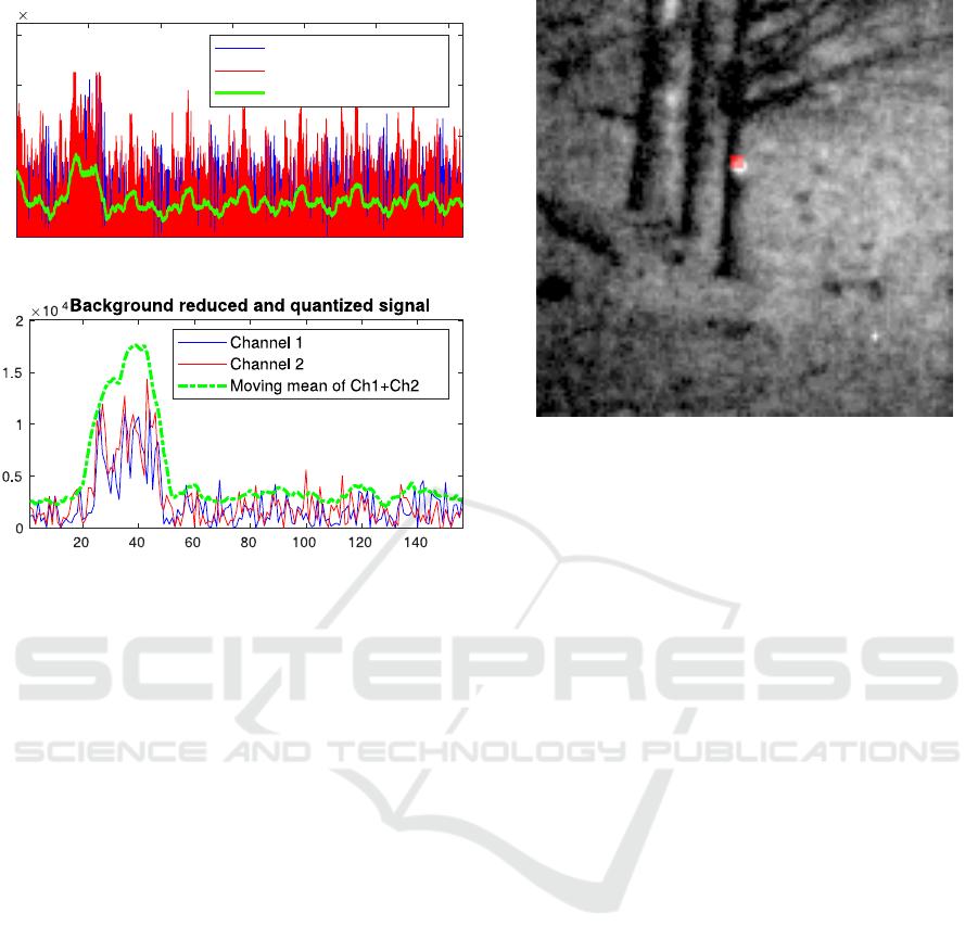
Figure 6: (a) Raw sampled signal with light flash (notice
the repetitions for each window which shows that the back-
ground is static). (b) Background reduced and quantized
signal from (a), by combining the signals and calculate
moving mean the light flash envelope becomes clear.
6 RESULTS
An example of the signals when an outdoor reflector
is pulsed with the laser can be seen in Figure 6. With
adequate SNR and number of patterns are sampled
during the pulse, the result will be a dark image with
the brightest pixel at the position of the light source.
In Figure 7, the restored 32 ×32 image (using 20
patterns) of the simulated light flash is superimposed
in red over the outdoor scene. 20 consecutive patterns
during a part of the 1 ms laser pulse are used to re-
store the red overlay image. The outdoor scene is also
captured at 128x128 resolution (3000 patterns with a
subsampling ratio of 18%), when the light source is
continuously on, thus visible as a small bright light.
Tests were made to evaluate the number of pat-
terns needed to locate a small light source, in this test
only one sensor was used. Instead of using a small
window for background reconstruction 500 unique
patterns was repeated. The laser was synced in such
a way that the laser was active for 500 patterns and
then inactive for 500 patterns. Thus we could cal-
culate background reduction for the whole signal and
wide range of pattern combinations (different sections
Figure 7: B/W image of the outdoor scene at 128x128 pixel
resolution, reconstructed using a subsampling ratio of 18%.
The Ø7 cm reflector, seen as a bright dot when the laser
is continuously on, is mounted on a tree at 350 m range.
The red overlaid image of the simulated 1 ms light flash is
reconstructed to 32x32 pixel resolution using 20 consecu-
tive patterns (during a pulse) and illustrates the capability
to detect and localize the flash at the same position as the
reflector (ground-truth).
of the signal) could be reconstructed to test if the
strongest pixel in fact was the light source for each
individual image. From the measurements, 500 pat-
terns were analysed and (M ≤ 40) different consecu-
tive patterns were used to reconstruct a large number
of images. The results from the experiments are pre-
sented in Figure 8. As can be seen, the probability to
locate the flash is almost zero below five patterns but
then rises quickly and after 25 patterns reaches almost
100. Because the patterns displayed on the DMD are
random, the probability to find the light source is de-
pendent on the specific pattern combinations during
the light flash and the SNR.
The same test was conducted both in- and out-
doors with variable length to the target, backgrounds
and resolutions. The trails showed that the key fac-
tor in order to detect and localize the signal was
SNR. With higher SNR the probability and number
of measurements needed for a successful localization
increased respectively lowered.
7 CONCLUSIONS
Conventional FPA-based solutions to high speed light
flash detection are challenging, due to limitations in
frame rates, signal processing demands as well as
transmission bandwidth requirements. The sparse na-
VISAPP 2021 - 16th International Conference on Computer Vision Theory and Applications
572

0 5 10 15 20 25 30 35 40
M, number of measurements
0
20
40
60
80
100
%
Optimal simulated
Outdoor
Indoor
Figure 8: Probability to find the correct pixel (illuminated
reflector) in the reconstructed image given M number of
samples, using one sensor. Green line shows simulated light
flash without noise, blue line from illuminating the reflector
indoors in a dark room from ca. 40 m, red line from outdoor
trials ca. 350 m.
ture of the transient and highly localized events how-
ever suggests that CS-based approaches might be use-
ful. Results of our initial experiments, based on long
range detection of 1 ms laser pulses with our DMD-
based SWIR SPC, show great potential of both detec-
tion and localization of flashes with the high sampling
rate provided by the DMD. A high (99%) localization
probability have shown to be provided after only 25-
30 samples, corresponding roughly to the pulse width
of the laser and to 2-3% sampling ratio of a recon-
structed image at 32x32 pixel resolution. Although
the initial focus has been given to muzzle flash detec-
tion, it is also conceivable that the system could be
used for sniper optics detection by using active CW
or pulsed laser irradiation, using similar techniques
as described in the paper. Detection of other transient
and spatially limited events of military interest could
be explosions and missile launches at longer ranges.
REFERENCES
Br
¨
annlund, C., Brorsson, A., Bergstr
¨
om, D., Gustafsson,
D., Oja, M., and Olsson, S. (2019). Detection and
localization of light flashes using a single pixel camera
in SWIR. In NATO STO SET-256 Workshop.
Br
¨
annlund, C., Tidstr
¨
om, J., Henriksson, M., and Sj
¨
oqvist,
L. (2013). Combined hostile fire and optics detection.
In Huckridge, D. A. and Ebert, R., editors, Electro-
Optical and Infrared Systems: Technology and Ap-
plications X, volume 8896, pages 124 – 132. Interna-
tional Society for Optics and Photonics, SPIE.
Cai Zhuoran, Zhao Honglin, Jia Min, Wang Gang, and Shen
Jingshi (2013). An improved hadamard measurement
matrix based on walsh code for compressive sensing.
In 2013 9th International Conference on Information,
Communications Signal Processing, pages 1–4.
Chen, J., Lu, L., Xu, Y., and Kelly, K. F. (2017). High-
speed anomaly detection with single pixel camera. In
Imaging and Applied Optics 2017 (3D, AIO, COSI,
IS, MATH, pcAOP), page JTu5A.3. Optical Society of
America.
Kastek, M., Dulski, R., Piatkowski, T., Madura, H., Barela,
J., and Polakowski, H. (2011). Analysis of multispec-
tral signatures of the shot. In Carapezza, E. M., ed-
itor, Sensors, and Command, Control, Communica-
tions, and Intelligence (C3I) Technologies for Home-
land Security and Homeland Defense X, volume 8019,
pages 171 – 181. International Society for Optics and
Photonics, SPIE.
Krieg, J., Eisele, C., and Seiffer, D. (2016). Electro-optical
muzzle flash detection. In Huckridge, D. A., Ebert, R.,
and Lee, S. T., editors, Electro-Optical and Infrared
Systems: Technology and Applications XIII, volume
9987, pages 74 – 80. International Society for Optics
and Photonics, SPIE.
Li, C. (2010). An efficient algorithm for total variation regu-
larization with applications to the single pixel camera
and compressive sensing. Master’s thesis, Rice Uni-
versity.
Oja, M. and Olsson, S. (2019). Stand-alone dual sens-
ing single pixel camera in swir. Master’s thesis,
Link
¨
opings Universitet (LiU-ITN-TEK-A–19/024–
SE).
Svensson, T., Lindell, R., and Carlsson, L. (2011). A
multispectral, high-speed, low-cost device in the UV-
MWIR spectral range. In Tissot, J.-L. M., Raynor,
J. M., Mazuray, L., Wartmann, R., and Wood, A.,
editors, Optical Design and Engineering IV, volume
8167, pages 559 – 567. International Society for Op-
tics and Photonics, SPIE.
Takhar, D., Laska, J. N., Duarte, M. F., Kelly, K. F., Bara-
niuk, R. G., and Davenport, M. A. (2008). Single-
pixel imaging via compressive sampling. In IEEE Sig-
nal Processing Magazine 25.2, volume 6065.
Takhar, D., Laska, J. N., Wakin, M. B., Duarte, M. F.,
Baron, D., Sarvotham, S., Kelly, K. F., and Bara-
niuk, R. G. (2006). A new compressive imaging cam-
era architecture using optical-domain compression. In
Bouman, C. A., Miller, E. L., and Pollak, I., editors,
Computational Imaging IV, volume 6065, pages 43
– 52. International Society for Optics and Photonics,
SPIE.
Tidhar, G. A., Aphek, O., and Gurovich, M. (2009). An
update on TED gunshot detection system development
status. In Andresen, B. F., Fulop, G. F., and Norton,
P. R., editors, Infrared Technology and Applications
XXXV, volume 7298, pages 530 – 540. International
Society for Optics and Photonics, SPIE.
Trzaskawka, P., Dulski, R., and Kastek, M. (2010). Con-
cept of electro-optical sensor module for sniper detec-
tion system. Proceedings of SPIE - The International
Society for Optical Engineering, 7834.
Wakin, M. B., Laska, J. N., Duarte, M. F., Baron, D., Sar-
votham, S., Takhar, D., Kelly, K. F., and Baraniuk,
R. G. (2006). An architecture for compressive imag-
ing. In 2006 International Conference on Image Pro-
cessing, pages 1273–1276.
Rapid Light Flash Localization in SWIR using Compressed Sensing
573
